[79FT]: Building Things |
 |
Wiring - Pt III
...part three: done!
| On: | Sep 07, 2020 |
| In: | [Chickenhouse Charger] Electrical Rebuild |
| Time logged: | 16.6 |
| Tags: | 6781G, MA5 Charger, electrical, panel, instruments |
... and the only bit of wiring left was the gauges at the panel.
It was not interesting in any way - mostly, lots of tying in awkward position.
A lot of stuff had to be done thru the front hole's headrest, while standing on a wing, and trying not to get "tangled" in the flying and landing wires.
Oh well.
I realized this was another mistake. Since all the gauge wires started at their transducers or sensors (amps, fuel and oil pressures, oil temp, and the like), I ran them "backwards" as one piece, and was planning to put on the corresponding D-Sub connectors in place.
What I didn't realize was how much pain it will be if I had to work in close quarters. And unfortunately, the 3-in-1 gauge - with the fattest of the connectors - required that.
What I should've done was cut the transducer and sensor's wires and made "whips" for them with connectors while on the bench. Then, I should've spliced them somewhere on the side of the airplane - yes, I'd have to do a lot of soldering, but that would've been better than what I ended up having to do...
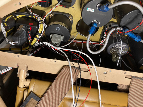
Instrument wires - and the back side of 3-in-1
You can see the DB-15 connector there - that's the 3-in-1. Sticking the wires thru the instrument hole, doing all the stripping and crimping from the panel side while sitting in the cockpit, and then tying the extra length up... maybe was possible, but seemed to me like it would be too much extra, producing ugliness and possibly rubbing on the structure nearby, so I decided to make that connector as close to the actual gauge as I could...
I tried it on the bench first, figuring out where I would put heatshrink, how much of the length is necessary for the connector, and the like.
Another interesting tidbit was that one of the connections had to feed two transducers off of the same one pin. Both wires were 22GA and I couldn't put them into the pin no matter how I tried - too much wire for one D-SUB pin's barrel. I'll show you the solution I used for that.
So, I bunched up the wires, put a round of heatshrink on, and prepped those power wires.
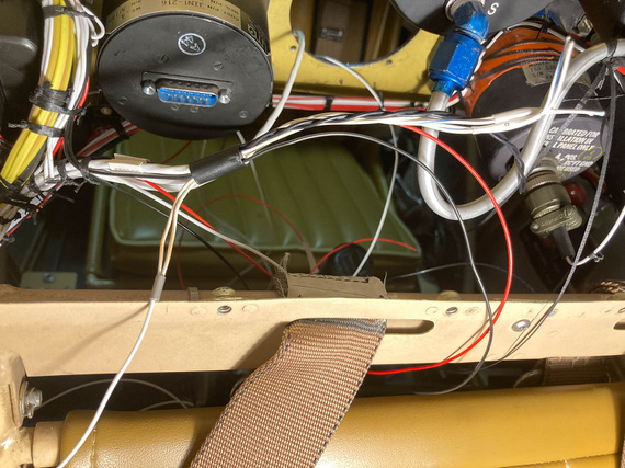
3-in-1 bundle
I bent the two power wires for transducers backwards "out" of the connector, and pigtailed a single 20ga wire to them. That looped back into the connector and hooked up to the pin.
Then, I set myself up on the wing, slouching over the front hole's combing, took my stripper, and stripped a wire... bam! 2/3ds of the strands came off...
What the..?!
I think the stripper pinched the wire when closing on it, and since I was so much out of position - practically upside down - I didn't notice...
And since I effectively just destroyed ~1/2 inch of the wire, and the wires were cut short....
I lucked out. The wire I was stripping was a standalone ground wire. Moreover, I had two more tails coming from the same source - for the other two gauges, and the unintentionally shortened tail I just made was just the right length for another gauge.
Phew. Only having to cut two knots, I re-routed the shortened wire to the other gauge, and that gauge's wire to the 3-in-1 bundle.
Tested the stripper multiple times. Yes, I think I just missed the right hole.
Making dead sure I was on this time, I tried again - phew. All worked out.
Slowly, everything got crimped.
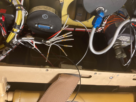
3-in-1 gauge pins
You can also see that "power loop" in the above picture.
Then, I installed the pins in the housing, and checked the 3-in-1 out. Used a plumber's gauge to pressurize pressure transducers with some appropriate amount of air and made sure the correct arrow went up on the 3-in-1, and by the right amount.
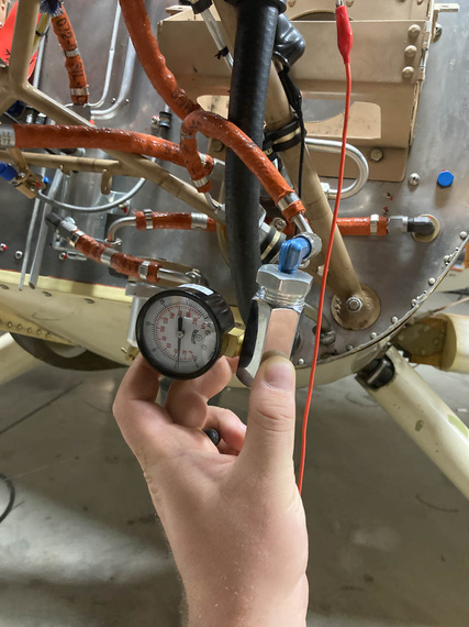
Testing pressure transducers
The other three gauges were much easier - because they were further from the 3-in-1 and tie point, for each of them I could trim and crimp the wires from the cockpit side. I had some fun times with the housing of the tach connector - a DB-9... UMA shipped me a weird sheet metal shell for it I've never seen that I think needs a special crimper to install, so I ended up replacing it with a regular cheapo plastic after spending what feels like a few hours trying to find out what the hell that shell was... Failed at that.
At any rate.
The final result? Well..
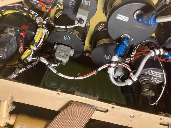
Beind the panel: done.
And with that, the re-wiring of the Charger was...
Complete!!!
"Leave five on the glide, have a nice ride, tower inside, twenty-six nine .... see ya!"
-ORD ATC
Up ↑
Wiring!
...part one
| On: | Jul 26, 2020 |
| In: | [Chickenhouse Charger] Electrical Rebuild |
| Time logged: | 95.6 |
| Tags: | 6781G, MA5 Charger, electrical, soldering, fwf, panel |
Well, damn. With almost a year (no, more than a year!) of my being a caretaker of the Chickenhouse Charger, I finally was about to actually begin what I have started - which was, putting in my wires.
I decided to start at the switches, and run from the panel forward. Some wires will terminate at the fuse blocks (power feeds), and some will go forward - to the front panel, voltage regulator, and firewall forward.
Then, I was planning to run a few wires backwards - the ones that were pre-terminated on my transducers (fuel, oil pressures, oil temp, and mag pickup for the tach).
Immediately, I will admit: that was a mistake. While the harness turned out alright, it could've been much neater - if I ran in one direction. I could've made sure the whole thing is wire to wire and perfectly clean. So I should've run front to back, because my pre-terminated wires all "started" upfront.
In other words, prop to tail. Well sigh. Next time. On the other hand, this approach would've made terminating switches at the panel a nightmare. That was, initially, the reason why I wanted to start at the panel - so that I'd pre-attach wires to switches, tie them up, and then trim them at the other end.
At any rate.... Shall we?
Prep
Couple things to knock off before I started wiring was to complete the back panel. One thing that was left was the compass correction card bracket. No problem, drilled and tapped a couple holes for #2 brass screws.
Here's Mr. M. installing it:
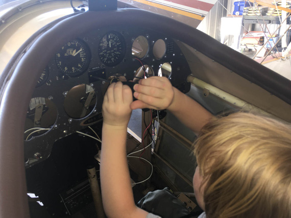
Compass Correction Card Bracket
The other one was the inertia switch for the smoke system. Glenn had it in for "safety": in the event of a shock (crash?) the switch breaks the circuit. I am.. not sure why he would have it, but he had it.
I considered not putting it back in, but what the hell.
Here's the switch:

Shock switch
The problem was, it sat tightly between other switches in the panel. With old layout, that barely worked; but with the new layout, and Honeywell double throw switches, the connector plug was getting in the way. So I had to resort to some vandalism. :)

Removed the connector and the shroud
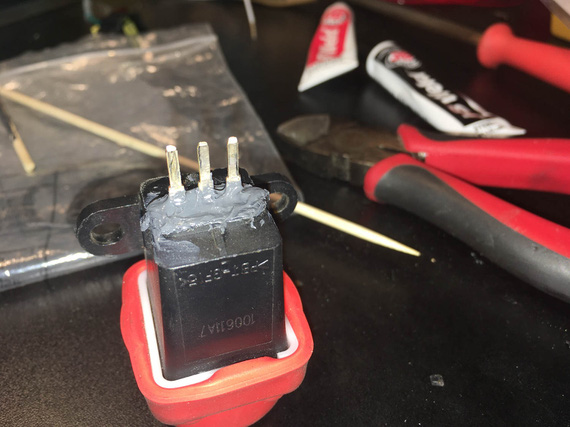
Epoxy around the tabs
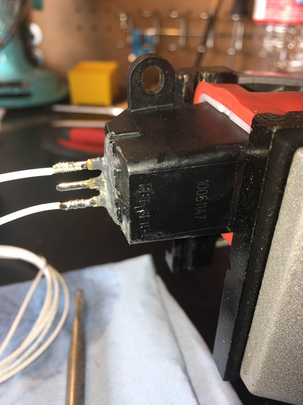
Solder!
And the switch fit nicely. Here it is, tucked between the switches. You can see how that connector would've interfered.
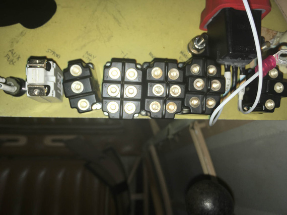
Shock Switch between other switches
The final prep thing was enlarging two holes for ground points to #10 and cleaning the back side up to expose nice shiny aluminum.
Panel
Now ready, I decided to install the switches first, and then wire them from the back. I needed a couple short jumpers though to connect them, and to set up some wires to be the exact length. That'd be impossible with switches installed in the panel (too little access), so I set up an old placard plate, installed switches into it, and worked on those jumpers and terminations on the bench before moving them to the airplane.
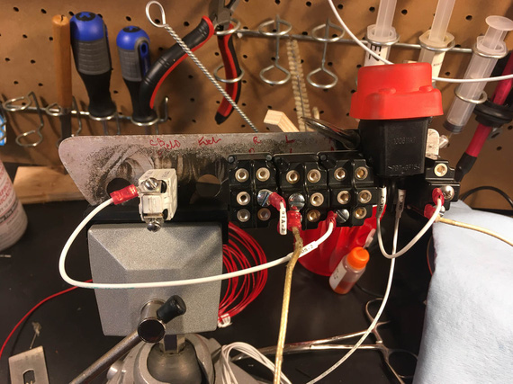
Switches on the bench mockup
Here's a couple more pictures of soldering and terminating fun pics:
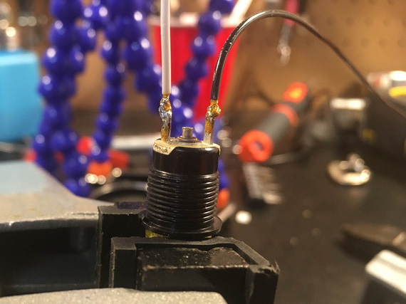
Warning light socket
(that flux got cleaned off, of course).
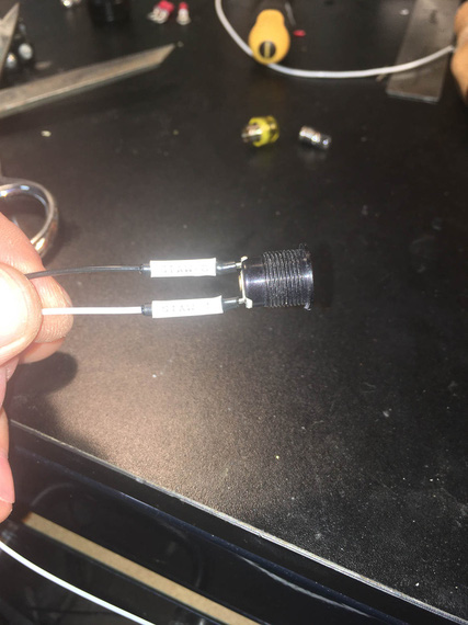
Tagged and shrunk
The heatshrink I'm using for these and in fact all my soldered joints is special strain relief kind with glue in it, specifically, Raychem SCL. It's 3:1 and it is very rigid - almost completely rigid. It definitely adds more support than the typical PIDG crimp used everywhere.
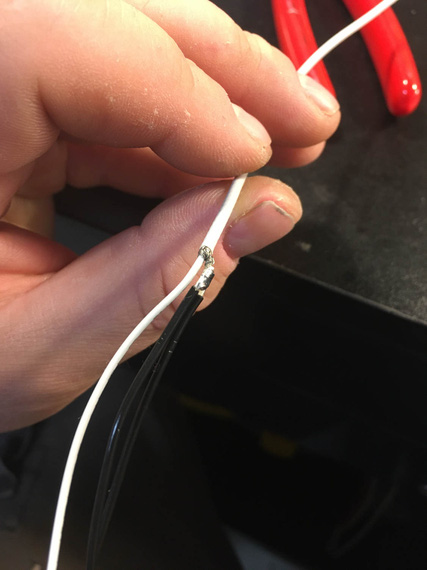
Pigtailing shielded p-lead
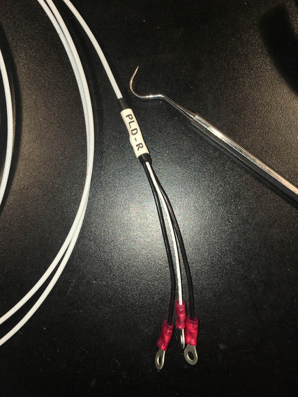
Finished with rings, HST, and tag
And then, switches went in, got tightened and straightened up, and I started running the wires.
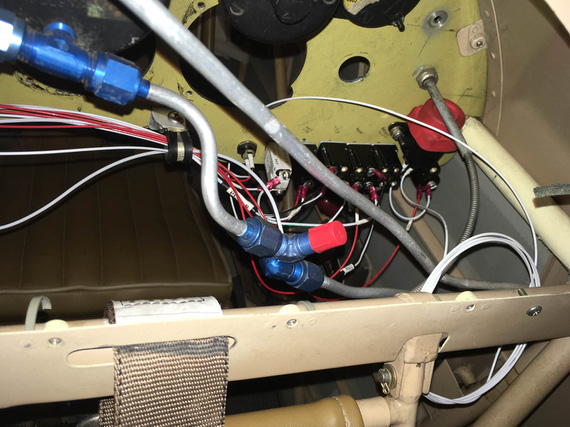
Somewhere in the middle of running the wires
I think it happened when I was yet again sitting in the cockpit, clicking the switches and enjoying the very well done Honeywell's action.....
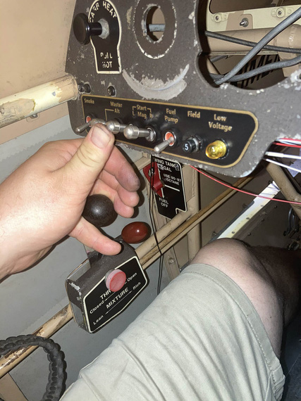
Engine starter engaged position - note that I can hit the starter and hold the throttle with the same hand
...when it dawned on me...
My three most important switches, L and R Mags, and Master, were set up with lockouts - you couldn't turn them on just by clicking them, instead, having to pull the lever first to move it to the "on" position. I mostly did that to protect from accidental too playful a kid in the cockpit.
But they weren't locked out in the "on" position!
Why is that important? Well, the Smoke and the Fuel Pump - the most operated switches on this plane - are right there. Note how their levers are shorter? If I accidentally hit the longer levered Master, or a Mag, switch, that would turn it off - with me potentially shutting down the motor. While a remote possibility, improving the situation would amount to just replacing the switches to the ones with lockouts in both on and off positions.
I don't know how I missed that when designing the original setup...
I decided to do it.
So out came the switches, I had to un-wire the terminals from the back. In went the order for three new switches with now correct lock-outs.
About a week later, I had them, and could proceed.
With left side wired up, I could tie it down. Mind you, access there is tight and from all kinds of weird angles :).
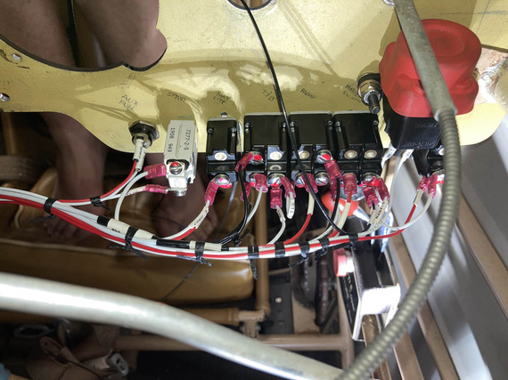
Tying left side
Some of those knots I did from the side. Some I did while sitting in the cockpit, using mirror as reference
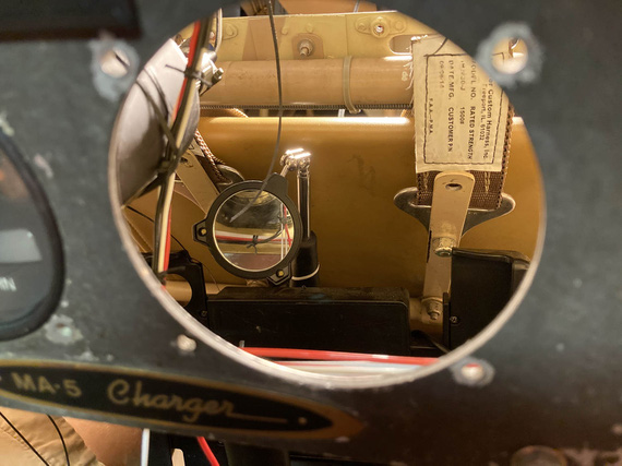
Look in the mirror!
Then, some "extreme soldering" to extend the panel lighting wires, that turned out to be a hair too short.
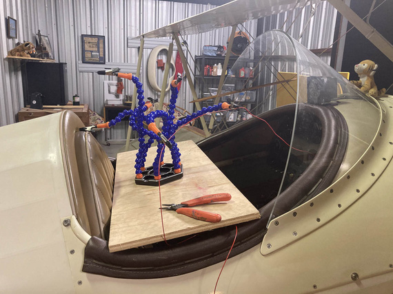
Extreme Soldering
For those lighting wires, and for the turn coordinator, routing took some fiddling with. My initial plan would've had them rubbing against the sides of the gauges, and I decided to bring them "out" and away - that's why I had to extend them, by the way.
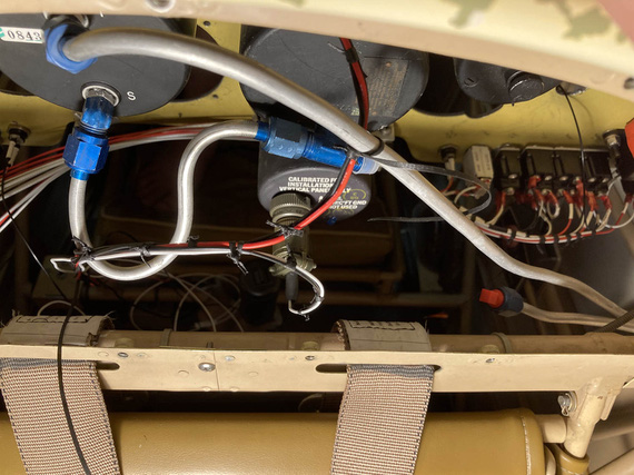
Lighting, and turn coordinator wires, test-tied
Note no padding on that pitot line: this is a temp, "sizing" pass: I am yet to finish assemble the back panel, and will add the right padding then.
The right side of the panel was much easier - it held much smaller, and simpler circuits, for lights and turn and bank.
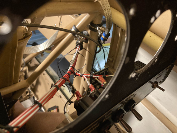
Right side
You can see the beginnings of the ground strap to bond the panel with the "side conduit", holding the fuse blocks and being one of the grounding points. In my original design, I had firewall, motor, "side conduit", and panel, as ground points - all bonded with those straps.
Here's the right side:
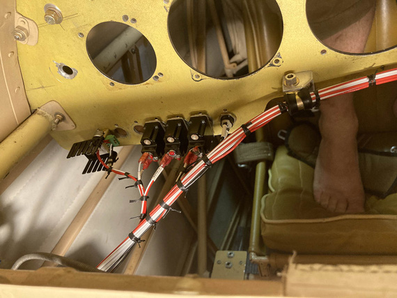
Right side
and the bonding strap
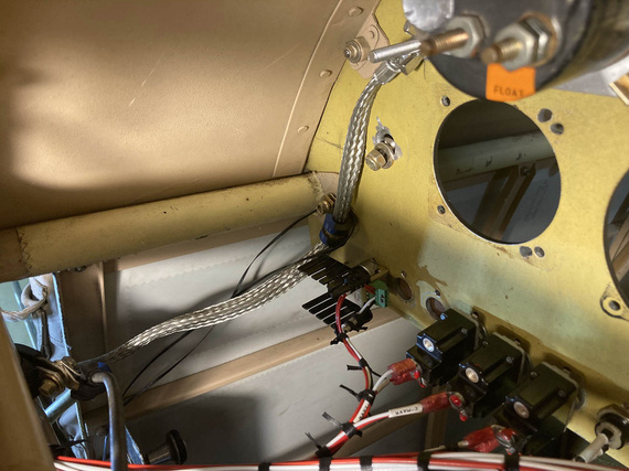
Panel bonding strap
(the bonding strap got enclosed in super flexible heatshrink just for neatness: this is a fit-up picture).
I also had some fun with ADELs right where the wires turn from the "side conduit" towards the panel. I had to clear and negotiate a couple bowdens, and the engine monitor harness was unwieldy.
I think that took a number of hours, just trying various setups, the final one that I really liked was this:
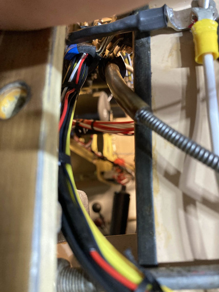
Engine monitor and carb heat bowden.
I replaced all the ugly zipties with lacing, of course :).
Meanwhile, on the outside, to keep the wires nicely separated, I spread them out in kind of a "fan" in the order they ran, back to front:
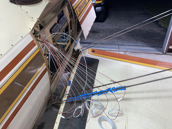
Wire fan
A day later, I replaced the tape with a comb. Yep, a cheapo $1 comb :) Worked out great.
And finally, before committing and continuing, I checked each wire for gauge, and proper circuitry.
Side Contuit, Part I
With all those wires sticking out, it was now time to start figuring out routing in the side conduit. All the wires that had to go forward had, well, to go forward.
After lots of fiddling, I ended up with this:
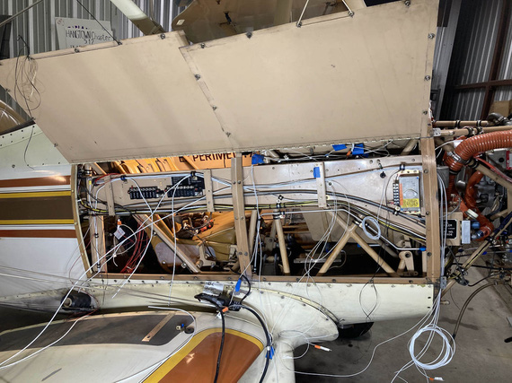
Initial stab at the side conduit routing
I had to clear all the brackets, and other sharp things. Ended up adding a couple more ADELs (and drilling holes in the conduit to accommodate). Also, reused some existing holes, made a few standoffs for ADELs and such.
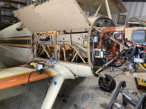
Another angle on the side conduit
And that was it for now. Now, all the other wires needed to join the main harness in the side conduit.
Front Panel
The most interesting piece in it was a Westach tach, that fed directly off of a P-Lead and required a .25A fuse. Glenn used a 1A classic glass fuse, but I decided to do it right. See, the thing is, if it fails "short circuit", that'd turn off the mag - I guess that's why the fuse is in there.
The tach would get another 20GA shielded wire, just like a p-lead, and I decided to join it to right mag's p-lead at the magneto - instead of splicing it into the p-lead running front to back in the side conduit.
But, back to the fuse. I figured, I'd build it into my connector that hooks up to the tach. Then, if blown, the connector could be rebuilt. Yep, it's more annoying than a regular replaceable fuse, but that circuit is not critical, and I had no room for a "regular" fuse block or holder.
So I got me a "legged" .25A fuse with a massive voltage rating (I forget what it was, but definitely above what a mag makes), and hooked it to a regular Molex pin.
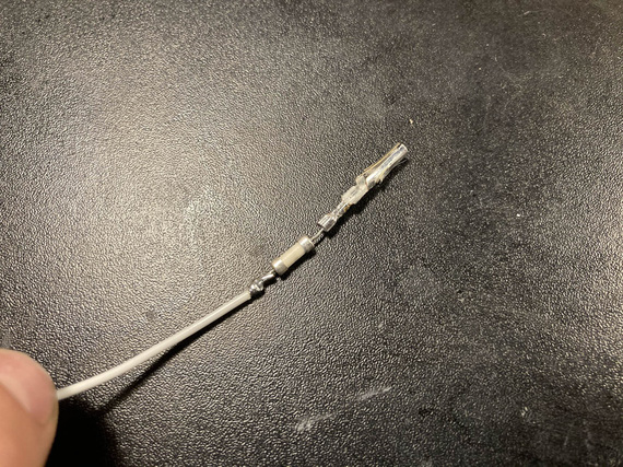
Inline fuse
Finished with SCL, it's encased in a plastic tube and is not moving anywhere. There's two layers there, actually: one around the fuse and the pin, and another around the housing and the inner layer.
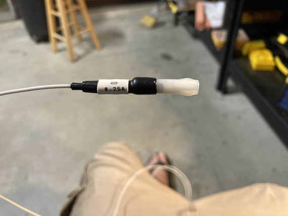
All finished
The final connector got set up like this:
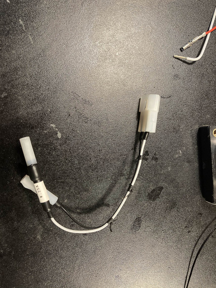
Inline fuse and connector
... and it goes on the tach like this:
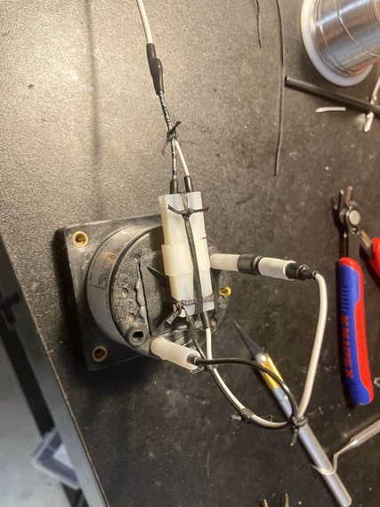
On the tach
The lead is just a regular pigtailed P-lead, of course. Notice how I like using SCL around individual Molex pins for added strain relief - that's because I can't produce good Molex crimps that I like; and I end up post-soldering them in addition to crimping. That strain relief ensures that soldered joint is firmly held immobile. Takes a bit of extra time, but I actually like that better than straight Molex crimps.
The rest of the front panel wasn't interesting, just annoying. There's only three circuits there: nav lights wires from the left wing run along the back of the panel to the right side where the conduit is, and then there's hobbs and tach, and that's it. It was just very annoying: with very little access, not being able to see things, and, being in the front hole, having to climb out and in every time I needed a tool I forgot to put close (when in the back hole, I can roll up a cart to it and have all my tools there).
Mirror was absolutely required.
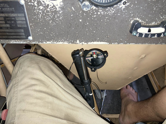
The only way to see things
I will admit to asking my dentist right around this time if he had a trick up his sleeve for this kind of mirror work. Of course, he said. Practice. Lots and lots of it.
Okay, so the front panel got done, and it's wires merged with the main harness.
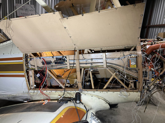
Front panel sub-harness joining the main
There, see, it's that small bundle going up and disappearing from view right in the middle of the "conduit"? That's the front panel sub-bundle.
Firewall Forward
The final set of wires to join the main harness were all the wires coming from the firewall side - mainly, transducers and other instrumentation wires, but also a couple wires for the voltage regulator.
This was precisely when I realized the mistake I talked about in the beginning - and ended up with less neat, and more tortured harness. Oh well.
I started up front, trimming and terminating my fat wires for the starter and alternator B-feed. Some more extreme soldering (to cap them), this time with a torch.
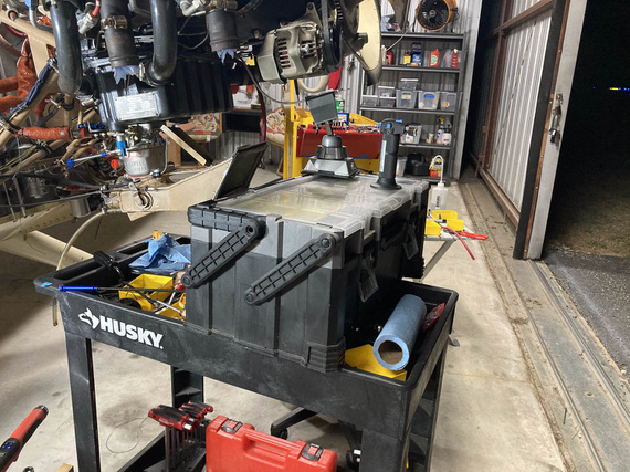
More extreme soldering
I tied up, and clamped the fat bundle to the motor: and apparently, didn't take a single picture.
Then, I had to figure out the diode for the Starter contactor - first of, it needed longer leads. There, instead of soldering, I used small barrel crimps from Molex along with heatshrink (I do use them where soldering is impractical, and I decided not to have soldered joints FWF).
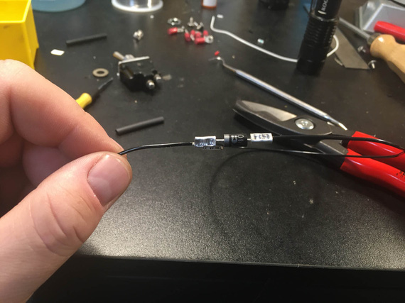
Diode with leads
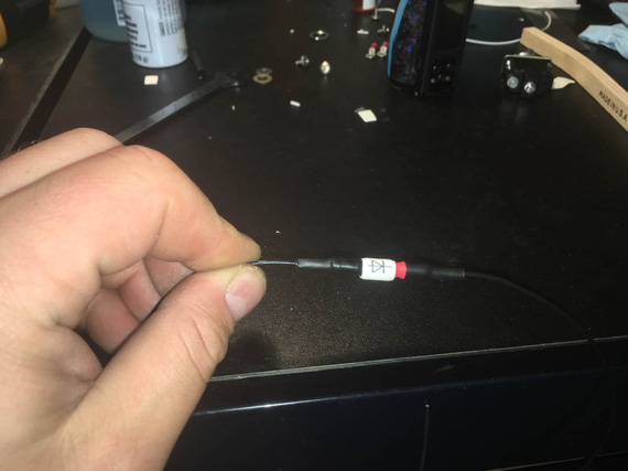
And all enclosed
And then, a simple ADEL to hook it up and hold it
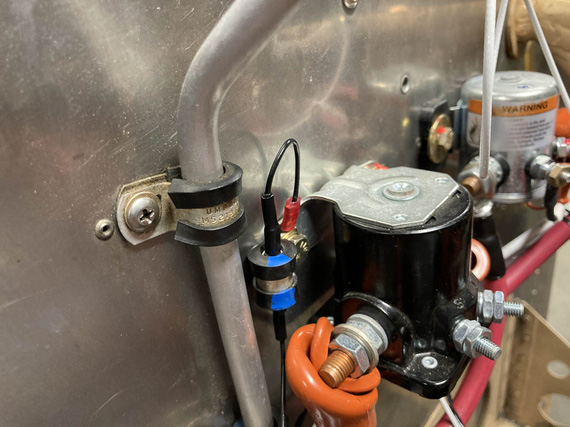
Diode all hooked up
And then, the ammeter shunt, and the sense wires. Those needed fuselinks - in liew of an in-line fuse. Simpler, and cleaner this way.
I tested them a while back, and am confident they'll work.
First, we take a wire 4 "gauge steps" thinner than the fused one (so 24GA for 20GA fused, etc). That goes into the "source" terminal.
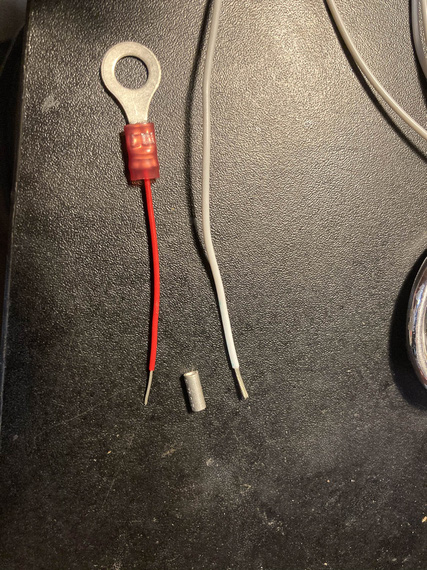
Beginning of the fuselink
Then, we hook it up.
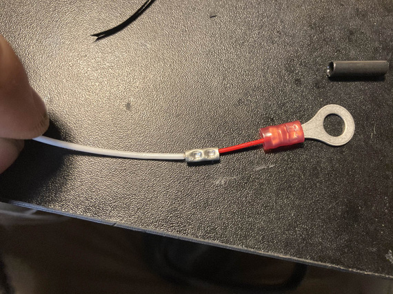
Hooked up to the protected wire
Then, some heatshrink over the splice, for strain relief.
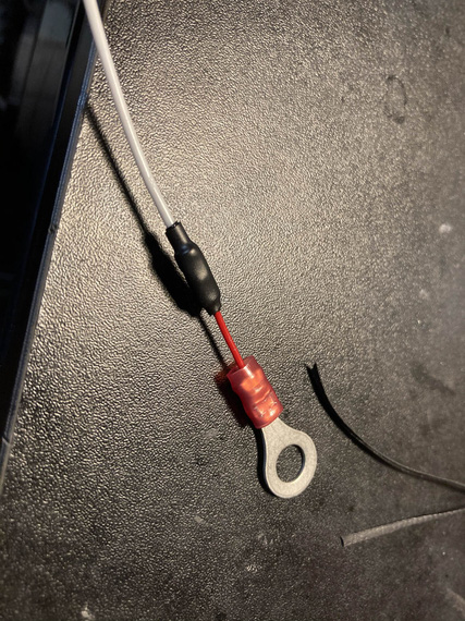
HST
Then, a bit of fiberglass sleeve to contain the "fire" when (and if) it does it's job, as in, burns thru the thinner wire that acts as a fuse in case of a short.
A bit of marking too. And a "cap"
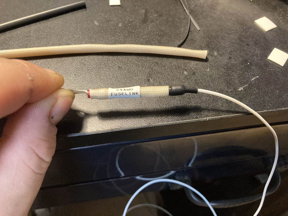
Capped and labeled
And finally, a couple knots to hold the sleeve better.
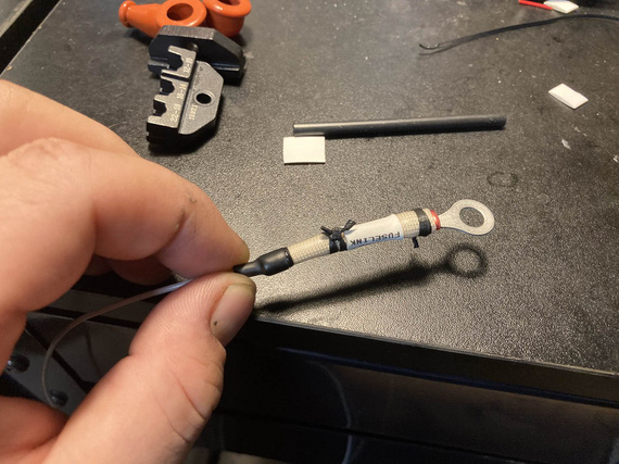
And laced
And finally, I finish installed all the engine transducers: pressures, and oil temp; and routed all their wires back into the side conduit and thru it back to the cockpit, adding them to the main harness. And that was that, for now - I plan to terminate them later.
Tail Light
I got rid of the belly strobe on the plane, because it was too heavy and too.. useless. Wingtip lights are gonna be the SkyBeacon and SkySensor from uAvionix (my ADSB mandate compliance :) ), and they have strobes: but they're not visible from the back. So I decided to replace the tail nav light with an LED nav/strobe.
Problem number one: no ground wire going to the tail light. For whatever reason, Remo decided to basically use the fact that the tail light is hooked up to the rudder with a pair of screws thru sheet metal of the rear rudder bow... I don't even want to begin to think what the ground path would be: hinges? control cables?
So, I needed a second wire.
Problem number two: it had to be one neat cable, and it had to be of a smallish diameter (Remo had an old 20GA wire, which is thicker than modern 20GA tefzel wire).
I decided to use a chunk of 20GA shielded - same ones I used for p-leads. Technically I guess you're not supposed to do that, but it's very far from all the antennas and I'm crossing my fingers that it won't create too much problems. Thickness was spot on.
So, I soldered the new piece to the old wire, and fished it thru using old wire as a pull. That part was scary - if that didn't work, I would've had to cut holes in the rudder to get a new wire thru.
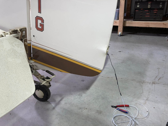
Fishing a new wire thru
The tail light shipped with a small Molex. Why not?
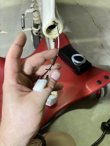
Connector terminated
The other end went onto the light, and everything got hooked up
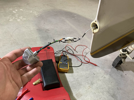
All hooked up!
On the other end (on the tail fin side) the wire went into a hole on the inspection cover, and had to join the wire coming from the front. And I had to have the ground there. You can see that area right behind the elevator on the "fishing wire thru" picture.
Problem number three: nothing to hook up the ground to in that area. The only option I figured out was to use one of the rivnuts that are attached to the tabs welded to the frame, hoping that there's no corrosion there between the aluminum rivnut and steel fuselage. I figured I'd use a way too long a screw thru one of the rivnuts when attaching that inspection cover, and then pull the ring terminal onto it, and secure it against the back side of the rivnut with a nut and a washer. Ugly? Yes; but I didn't have any more options. Really, the right way to do that would be to run two wires from the pilot panel all the way back, but.. I'd have to start cutting fabric for that.
So, I attached the positive to the wire that was already there, terminated my ground, hooked everything up, hooked up some power, and...
Nothing.
A bit of debugging showed that... ground was the problem. Damn! I picked the wrong rivnut, I guess - it had corrosion. The one right on the other side though showed the right voltage when measured against the positive lead, so I just moved everything to the other side, and...
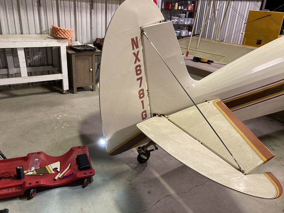
Let there be light!
Side Conduit, Part II
At this point, the main harness looked something like this:

Main harness: complete, but not terminated
Now was the time to go thru it, cockpit to firewall, and terminate all the fuseblocks, and tie and zip everything up.
First, conduit, cockpit side. Lots of crossing things, lots of padding for bowdens where they cross the wires (I used the right sized vinyl tubing from my local friendly Aerospace Depot, and lacing to tie it).
Engine monitor harness got covered in tube for quite a distance - there was no way to keep it off and not rubbing on the conduit.
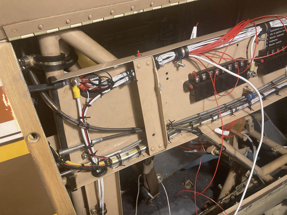
Cockpid side conduit
Fuse blocks got their placards. No, Mr. D., I am not doing brass placards again!
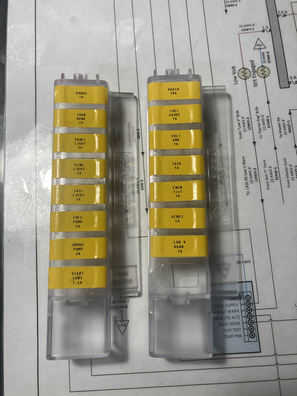
Fuse block covers placards
And then, slowly, methodically, every power wire got it's ring terminal. I added a bit of a "service loop" and used a ruler to try to keep each next wire exactly the necessary amount longer to reach the next terminal screw... Didn't work out too well, but close enough.
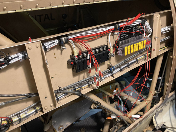
Rings!
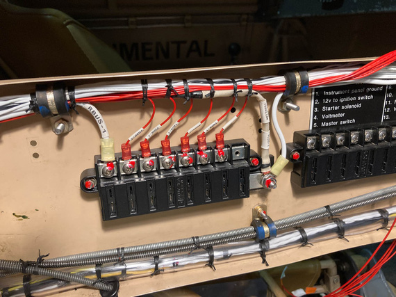
Tied up and hooked up
Another side got the same treatment, and then...
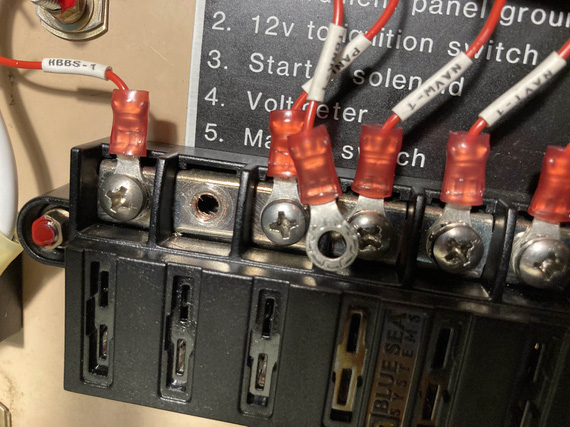
?!?!?!
Did I just strip a terminal block hole?? Yep. I did. I blamed a bad block and definitely, positively, absolutely not my overtorquing the screw. Nope. No overtorquing. For sure!
So, had to get a new block. They're $35 so I figured I won't try to repair this hole to use an upsized screw....I'd spend more money on shipping small-headed #10 screws (the screws in the terminals are #8 but with small "oval" rather than "pan" aviation style head, so I'd have to get me some decent screws from McMaster.. by the time I'd be done, it'd be close to those $35).
So, fuseblocks. From there, it was just turning everything pretty.
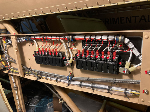
Both fuseblocks done and tied
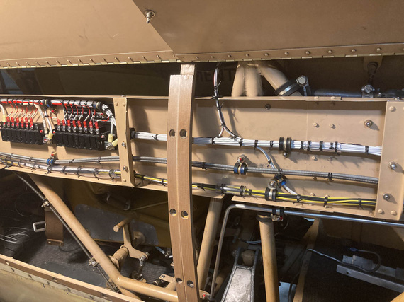
Mid section
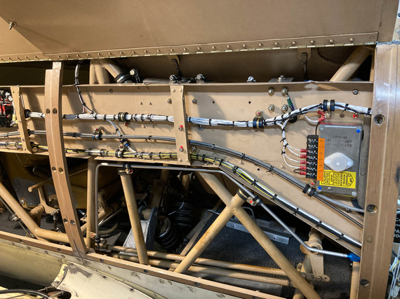
Voltage regulator
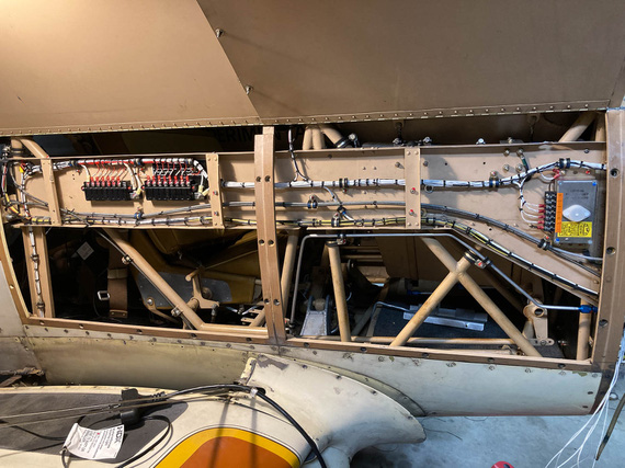
The whole thing
Sorry, couldn't resist doing a "before" picture.
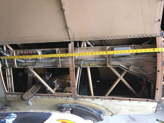
Before
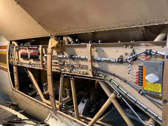
Jack likes this!
It at first you don't succeed, well, so much for skydiving.
Up ↑
Drilling the Panel
...misery turned happy times!
| On: | Sep 10, 2019 |
| In: | [Chickenhouse Charger] Electrical Rebuild |
| Time logged: | 5.9 |
| Tags: | 6781G, MA5 Charger, electrical, panel, drilling |
...this is important. Stick a pin in it.
Remo had these nice placards all over the airplane. Professionally done. Very well looking. He probably ordered them somewhere, or used a technique I am not aware of.
These placards are mostly glued on, and do not come off.
How do I know?
Well, I needed to remove one, in the side conduit. Here it is,..
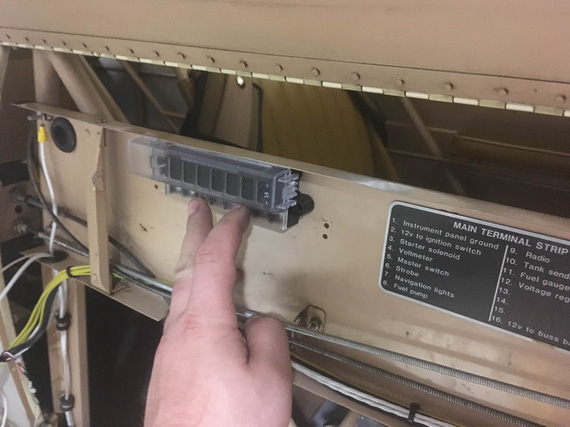
Placard
..to the right of the future fuse block. It gets in the way - there will be another fuse block there to the right of the one on the picture. And I can't rip it off! I can't remove the conduit to immerse it into whatever solvent will cut the glue without some major surgery, so I guess the new fuse block will go on top of it.
Why am I telling you this?
Ha!
You'll see.
Read on.
Switch Anti-Rotation Holes
You have probably figured by now that I have a taste for misery, and for ranting about how miserable that or this was :). If you read a few notes in this Dear Diary, you will notice a trend - that I tend to come up with ways of making myself aggravated, very consistently and reliably.
Well, this time it was the "anti-rotation" holes for switches in the panel; and the plan was to drill them from the back side of the panel not quite all the way thru (yay, no access and contortionism again!)
Every switch, circuit breaker, and certainly, a dimmer, comes with a "keyed" washer to prevent it's rotation. That means you're drilling two holes - one for the appliance (switch, or whatever), and the other for the little tab that's on the washer.
Picture explains this better. Here is a little hole template I quickly drew in Solidworks, properly dimensioned, with washers from (left to right) the circuit breaker, switch, and the dimmer.
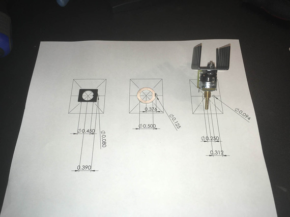
Holes template
See, Remo didn't have those "secondary" holes on the panel - so I had to drill them (especially for the dimmer).
But wait, you ask. If you drill holes, that will be ugly - a hole next to every switch?
Yup. Aha. Agreed! Though the nuts are supposed to cover them, they, I'm pretty sure, from my testing at least, wouldn't have...
No problem! Remo made the panel from 1/8" thick aluminum, and I needed maybe half that much for the tabs to go in. So the plan was to very carefully drill them just deep enough to house the tabs.
Made me a nice little set of templates...
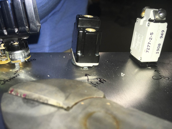
Templates in the making
...out of a small piece of aluminum, drilled holes using my paper template, and cut them up...
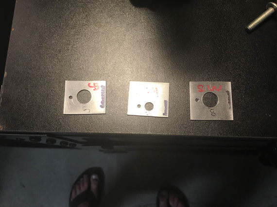
Templates, cut up
...and cleaned up the holes and edges.
The plan was, to put a template like a "washer" around a switch/CB/..., and center punch the secondary, small, hole, thru it. Then, I'll have punch marks to drill, and will have to either get to them from the side of the plane, or, more likely, from the back of the panel while sitting in the seat and not seeing where they are while drilling, using a mirror to position the drill first.
Like I said, I have a taste for misery.
So there we went, punching the back side.
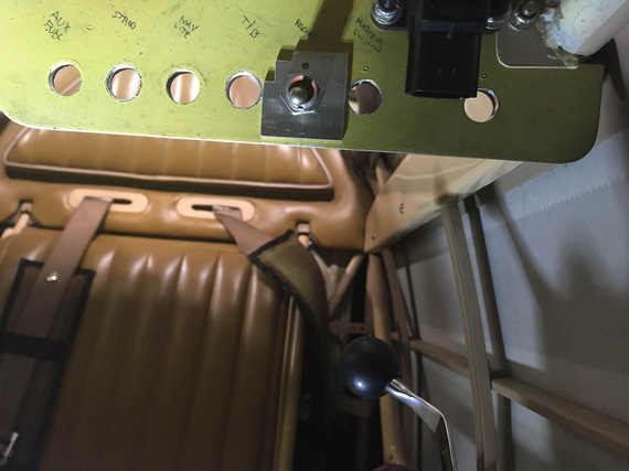
Center-punching on the back side of the panel
Click-clickity-clack.
Cling! Ding! Ding dang dong.. it sounded like a chunk of metal just fell off the plane and dropped on the cockpit floor.
!??!?@??!??! What the h... did I break?!
I crawled out from behind the panel and looked into the cockpit.
On the floor, looking at me, and almost smiling, was...
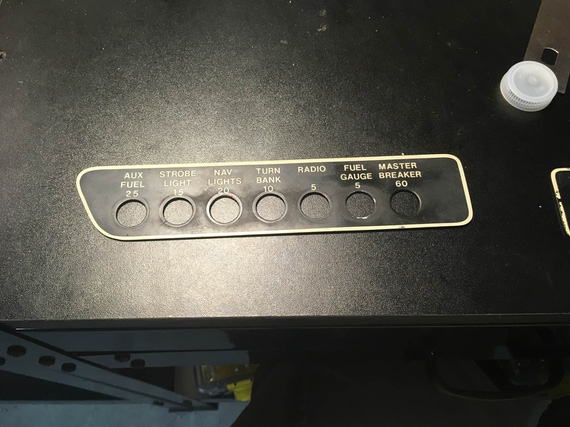
Placard!
...this. Remo's placard that went around the switches. Like so:
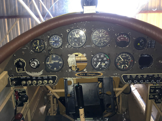
Placards - in place
Wait, wait wait wait. It came off. But it will be held back by the switches' nuts when the switches are in. And.. cover the holes! That means, I don't need to drill the holes from the back side and worry about punching thru (or not going deep enough) - I can comfortably sit in the cockpit and drill them from the front! All the way thru! The placard will cover them! In my search for misery, did I luck out?! :)
In retrospect, this (and the opposite side's) placard were probably not glued. No need - switches' nuts hold them just fine.
They were stuck because Remo probably installed them on top of the paint that didn't fully cure - and it just stuck to the backside of placards over the years, under the pressure from switches' nuts.
I stuck my nail under the opposite side placard, and it came off with a little force.
Ha!
Well, it was smooth sailing from there...
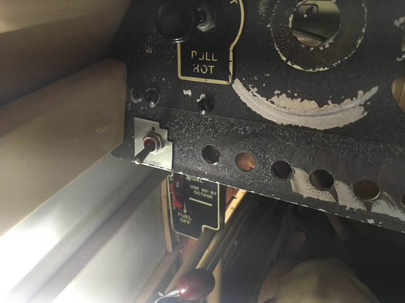
Marking from the front
... relatively speaking, of course. I still had to hold up the vacuum with my knee, and maneuver the sharp drill, making sure to be extra careful not to poke it into anything important (like, fabric on the sides).
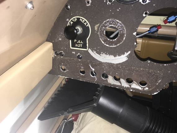
Curlies!
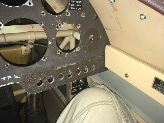
All drilled!
The ones on the corners were annoying; but I already had the drill bit installed into one of my hex drill adapters - so a 90 degree adapter was not an issue. Didn't even need an angle drill.
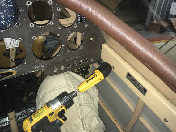
Angle adapter for the side hole
Happy end!
Dimmer Pot
That sucker has 1/4" diameter threads; and all the holes I have in the panel are 1/2... Without some serious bushings, or other mods, or a new hole.. ugh.
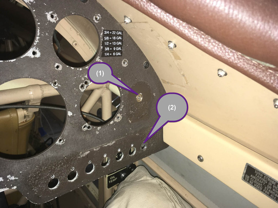
Possible pot locations
I was hoping to stick it into the old "Master Circuit Breaker" hole (marked (2) above), but it was waaaay too big.
Looking around, looking around.... aha! Here's a number 8 or 10 screw plugging a hole! I can enlarge it and we'll be in business! (marked (1)).
Yep. Good luck, buddy. That was an even bigger hole that was plugged with a #8 screw in a countersunk finishing washer... hmmm... maybe that will work out for the pot too?
You know, drilling a #10 countersunk washer to have a 1/4" hole in it is... hard? Annoying? You can't really grip it in any manner without damaging it, you can't hold it in your fingers... I think I lucked out on my third try, with combination of a Unibit and light clamping of that washer in a vice.
With that re-drilled countersunk washer, the pot mounts just fine in hole #2. And #1 got plugged back :).
Compass Mount
Well, after all that excitement compass mount was almost anti climactic. I toyed with the idea of putting it into the panel (and relocating G-meter into a new hole I'd cut around where the ignition switch was - see, after having failed relocating Hobbs there, the idea of still making a bigger hole in the panel keeps nagging me :).
No good. When that much down, too much steel around it confuses the compass to the tune of about 30 degrees... No need to add extra problems in already a magnetically problematic plane.
So, top it was to be. The windshield will get in the way, but I really, really didn't want to take it off (~20 #6 screws and nuts in a tight spot is no fun).
Eyeballed the bracket alignment with the fuselage centerline and put it in the right spot...
Damn! Sharpie's too tall to get in there to mark the holes vertically. "Angle Sharpie Adapter"... hmm..
I know!
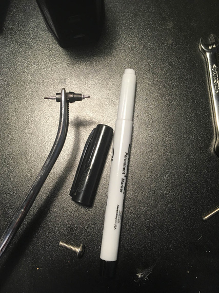
Angle Sharpie Adapter
A bit of disassembly and forceps do the trick ;).
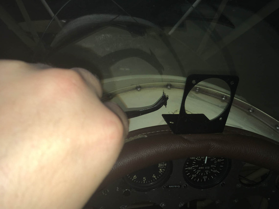
aaaand, mark!
Holes punched and drilled, I added a bit of rubber foam under a portion of the mount to "eat up" uneven surface created by combing...
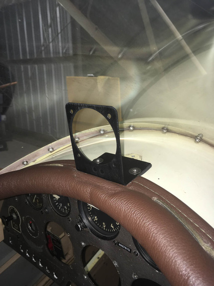
Mount mounted
...and voila...
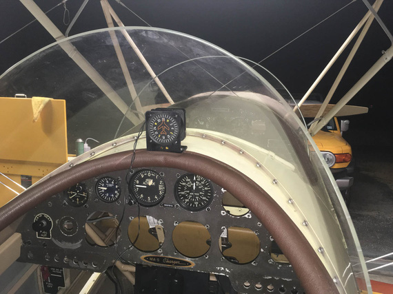
Vertical card compass!
Side note to attentive folks: yes, I know I need brass hardware - those CSK washers and SS CSK screws are temp fasteners I used to test positioning. It will be brass, I promise :).
PPS
Oh, by the way, the best accompaniment (score? ;) ) for working on a biplane is...
... The Chairman, of course!
The three most common phrases in airline aviation are “Was that for us?” “What'd he say?” and “Oh Shit!” Since computers are now involved in flying, a new one has been added: “What's it doing now?"
Up ↑
FWF, Side Conduit, and Panel
...messing around trying things
| On: | Sep 08, 2019 |
| In: | [Chickenhouse Charger] Electrical Rebuild |
| Time logged: | 21.5 |
| Tags: | 6781G, MA5 Charger, electrical, fwf, panel |
I was on the fence about making this entry as multiple separate ones versus just one giant one... After all, it covers quite a few, mostly unrelated, things that I did in the last few days, and it would've made sense to keep them separate.
However; finally decided to make just one big article with all of them. None of them are finished; but somewhat a decent chunk of work is - I think I have mostly figured out where everything will go and how it will all come together.
I guess, what I'm trying to say is, if you clicked on the "Panel Layout" entry in the Log, and are trying to figure out why are you seeing notes on Firewall Forward, just keep scrolling :).
Diagram
I have updated the electrical diagram, version 2 is here.
- Main Connector is gone. I was convinced that reliability concerns outweigh the benefits of having it. Plus, I have very little precious room to work with.
- Physically, it's easier to hook up the LR3C Sense wire to a different spot - on the Shunt stud rather than to the Master Contactor/Starter Contactor jumper directly. It makes no difference, it's the same circuit - just a different hookup spot to it.
- I also fixed some typos, and cleaned up a bit.
Firewall Forward
I started trying things around firewall forward while figuring out routing and lengths for carb control cables, and continued afterwards.
Contactors and Beefy Wires
Contactors
It became obvious fairly quickly that I won't be able to use the nice B&C Starter Contactor because of it's mounting holes not being the same as a very common SS581 Starter Solenoid that was set up by Remo. Also, the way terminals were set up on the B&C Starter Contactor would have made them closer to the carb control cables. And, I didn't want to drill more holes in the firewall.
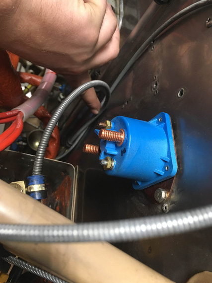
B&C Contactor
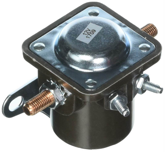
SS581 Contactor
So I decided to go with SS581-style and ordered one from Vans. While waiting for it, I used the old one just to mock things up.
And because it doesn't have the spike catcher diode, I had to get me a couple IN5400s, and soldered an extension lead to one of them.
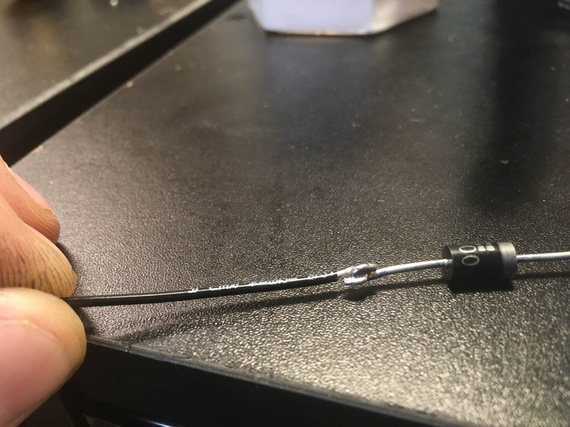
Extension lead
The other leg will get a crimp ring terminal. I had to do that 'cause the diode leads themselves weren't long enough.
Battery and Starter Wires
Those are the thickest wires, and routing them is more complicated than the other ones. In addition, the battery + -> master contactor wire is the only wire that can't be turned off, and therefore needs to be very well thought out and as short as possible.
Here's something else, too. The Charger was set up to ground the battery to the motor. So far, so good - starter is by far the largest consumer in the electrical system. However, nothing was done to ground the motor to the rest of the airplane!
So the rest of the system was probably grounded via whatever metal to metal connections there were on the motor. Control cables and braided fuel and oil hoses? ;) Airbox bowden "carb heat" cable... I can't think of much more else.
Initially, I was planning to run a ground strap braid from the battery negative to one of the bolts holding the battery box to the firewall, but with fuel system components and control cables around, just couldn't figure out a good way to run it and support it. I had to end up settling for running it to the engine mount instead.
So the bottom line is, the negative 4GA cable is gonna go to the motor, and parallel to it a braid will go to the motor mount. I also figured out a clamp arrangement with some standoffs that will keep the wires neat and organized.
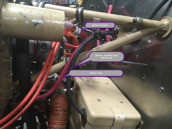
Beefy Wires - side view
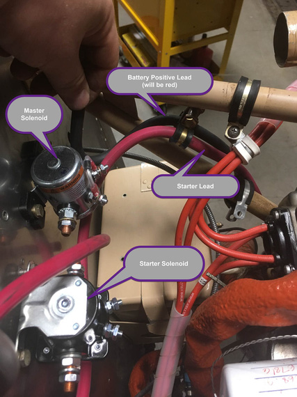
Beefy Wires - top view
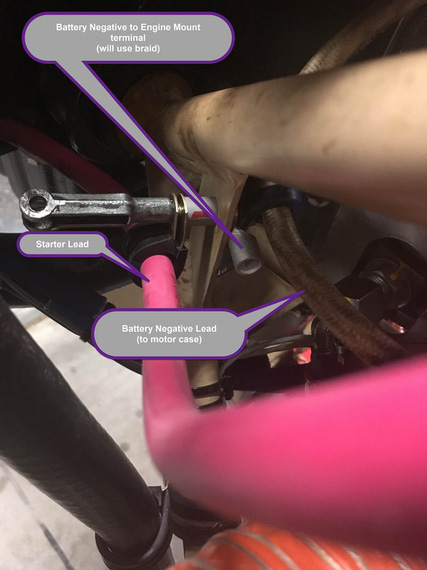
Negative leads and grounding
Oh hey, and I practiced my lacing on those ignition wires. One of my plans is to excise all the zipties I can get to, and replace them with lacing cord ;).
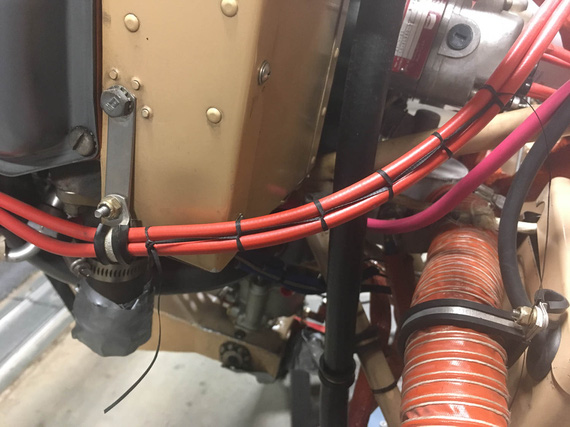
Laces
ANLs and Shunt
ANLs and the Ammeter Shunt will go to where no man had go... 'cuse me, to where the old Voltage Regulator was. Like this:
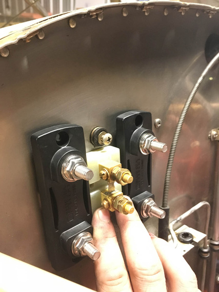
ANLs and Shunt placement
I will need to make a backplate for them to re-use the old voltage regulator mounts, and not have to drill new holes in the firewall. I used my Solidworks templating trick, and made me a nice template...
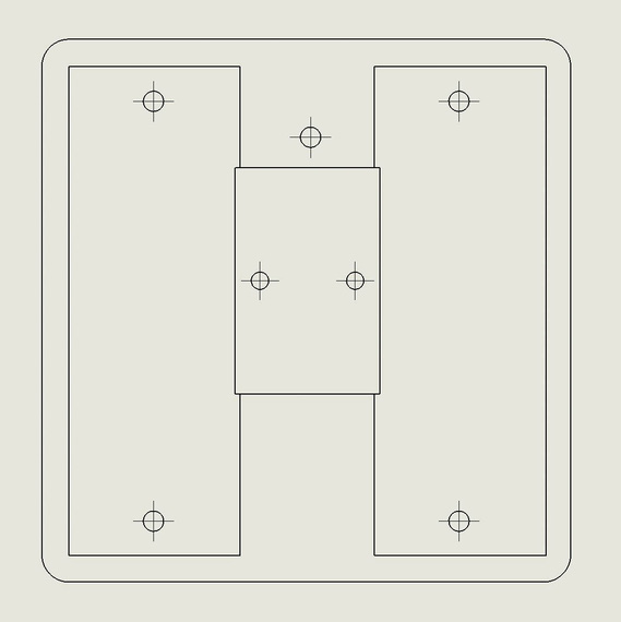
ANL template
... and a mockup (with material, as usual, courtesy of USPS).
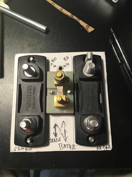
Mockup backplate
The shunt is offset "down" due to the top hole in the backplate (which will have one of three holddown screws to hook up to the old voltage regulator mounts), and I couldn't use buss bar stock to connect the stud terminals on the shunt and ANL bases - if I were to do that, it would not let the ANL covers to come on. So, before doing anything drastic, I decided to check to see how it would look with the wire jumpers
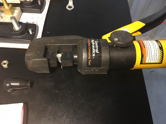
Crimper
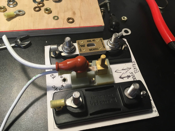
One side done
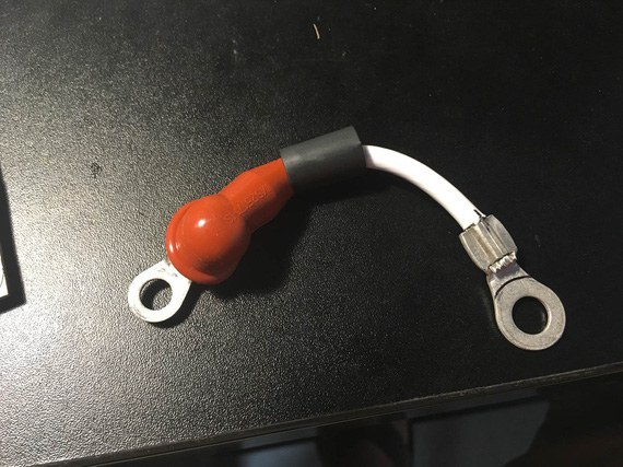
Second ring on the jumper
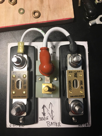
Done
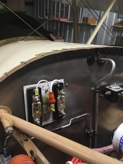
On the firewall
I liked the way jumpers came out a lot, and will probably keep them that way. They do add just a bit of weight, but not enough for me to worry about.
Side Conduit
The Voltage Regulator and the Main Terminal/Fuse Block were to go to the Side Conduit running alongside the fuselage.
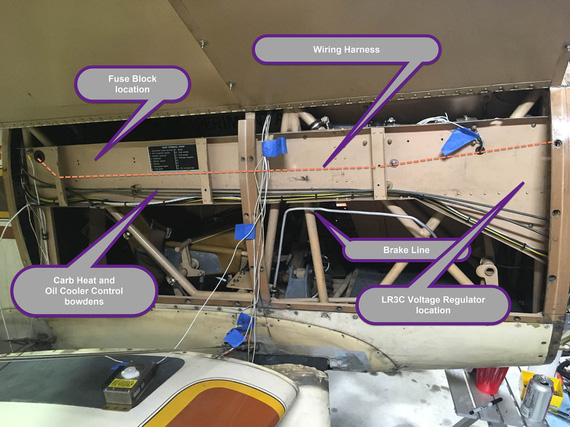
Rough component locations
I had to relocate the bowdens lower to free up some space. The Oil Cooler box on this plane is all sorts of weird, including a flapper valve controlled by one of those bowdens that closes up the airflow to it (which is not enough to begin with; being a 1.5" SCAT takeoff off of back baffle.. but don't get me started on that). That cable turned out to be too short when relocated - but I lucked out - Glenn had a bowden going to the Rotec TBI that I removed for "prime" function, and that bowden was plenty long. I'll trim it to final length when I'm done in that side conduit.
The brake tube was running inside the conduit, and I will have to relocate it to run below the conduit and be supported by adel clamps. For now, I unhooked it and used it to somewhat mock up the new run. Tube and fittings ordered, and tubing bender already here!
Fuse Block
I was gonna use a 20-position fuse block from B&C. Well, that didn't go too well.
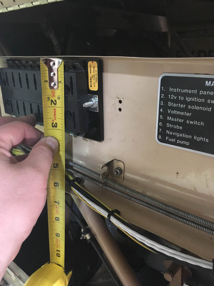
Fuse block
Tight! I basically lose the whole top row of fuses with it. Not enough room....
After poking around the Internets for a bit, came to these nice fuse blocks made by Blue Sea Systems. Longest ones they have are 8 fuses, so I will need two (if I recall correctly, I have 13 fuses in the diagram currently, and I want some spare positions for later if I need them).
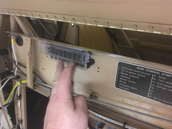
Blue Sea Systems fuse block
Much better! Plus, they use ring terminals rather than tabs - and while tabs are light and simple, I don't like them. Removing them is hard, and, when removed, the terminal loses a lot of it's grip. It's almost like an "assemble once" type deal.
Voltage Regulator
With how the wire harness is gonna go in that conduit, and with bowdens being where they are, the best orientation for the Voltage Regulator would've been "upside down", with terminal strip up.
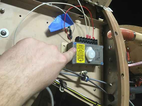
Upside Down orientation
Damn you, the yellow sticker on the regulator! DAMN you! (hint: read it :) ).
Mounting it sideways, I'd have a line of rivet heads under it - which I didn't want to deal with.
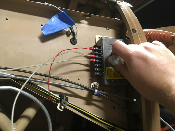
Sideways orientation
And mounting it down... Down was annoying because of the clamp for bowdens and bowdens close there. That would also complicate wiring.
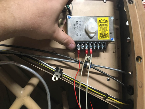
Down orientation
Upside down would've been perfect... except for that yellow sticker :). So, I decided to Hail Mary and asked nice folks at B&C about what they thought.
See, the problem is I know why they wanted the terminal strip to be pointed down. It's so that water won't get into the box in case of condensation accumulating on it. But I thought, maybe I can seal it somehow?
The answer from TJ at B&C was a resounding no. Right side up, sideways - but not upside down.
So I mocked up the right side up mounting...
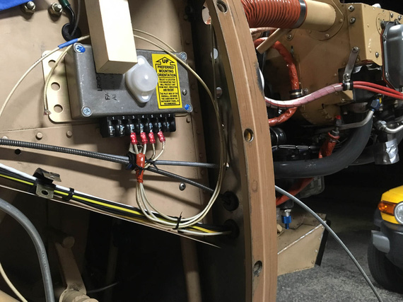
Right side up mockup
Yuck. Yeah; it'd work; but it's ugly as hell.
The only other option would be sideways, but on "standoffs" of sorts to clear the rivet heads. I mentioned that to TJ, and he said that that could work, but I should check if I can access the voltage adjustment screw on the top of the box.
Damn it! I forgot about it. On the top of the box there's a plug over a hole that opens up access to a tiny screw to adjust buss voltage - basically, to fine tune how much volts the battery sees. Not something you do often, but you want to be able to do it.
But then, TJ mentioned that he saw the holes in the firewall and that might be the saving grace.
Bingo!
I tried it out again in vertical, now with mocked up standoffs
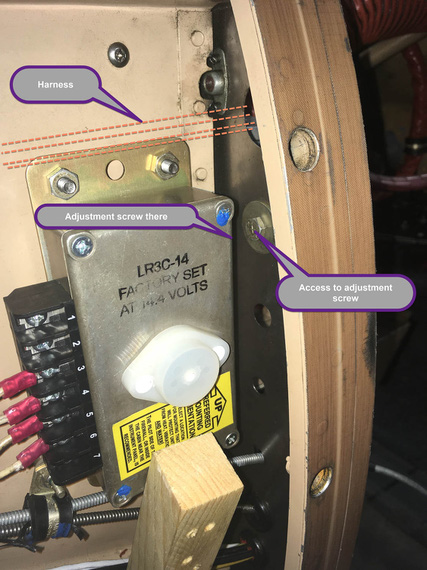
Vertical
With just enough aggravation due to bad access (mandatory in aviation pretty much), you can undo the bolt covering the hole in the firewall (this hole was left over from the brake line relocation), pop the plug on the voltage regulator, and just have enough access to the adjustment screw.
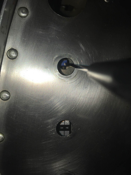
Adjustment screw - firewall side
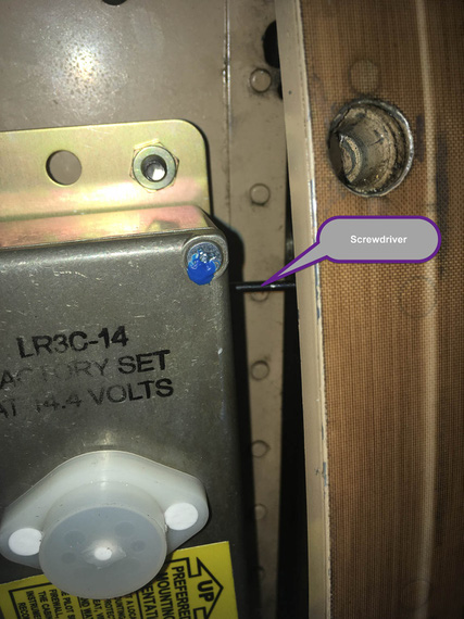
Adjustment screw - conduit side
We got ourselves a winner, I think!
Panels
Hobbs
Hobbs was on the front panel, probably because of space issues on the rear panel.
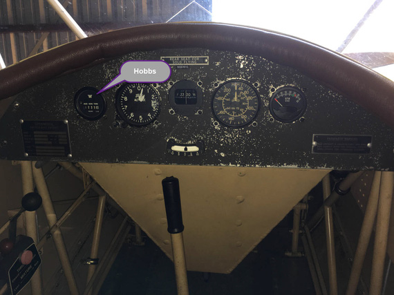
Hobbs meter
"Aux Generator", eh? :) (read what the gauge says).
Well, I had this unsightly hole left over after removing the ignition key switch...
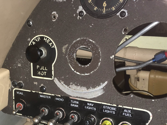
Unsightly hole
... and I thought, maybe I could put the Hobbs back there?
My initial tests with one of the 2 1/4 gauges I have removed seemed to have been okay: there was just enough room in there to get another 2 1/4 gauge in.
So, I got me a very nice panel punch that could make a nice, round, clean hole in place.
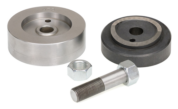
Instrument Hole Punch
Well, next was to remove the Hobbs from the front panel. That was an hour of contortionism. The Hobbs is held by an aluminum backplate and four nylock nuts, so I had to have a wrench over them the whole time. Oh, the screws are way too long BTW, so taking all them out took about five times more turns than it should've, while I was wondering if my wrists will take this much flexing, twisting, and bending any longer.
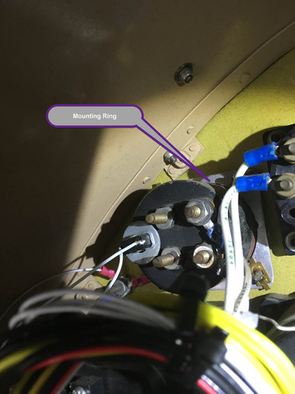
Mounting ring
This is a pic from the fuel quantity gauge held in the same manner, but here he's using brass flat type nuts that you can hold with your fingers. On the Hobbs, it was nylocks.
Anyway, I got it out. And then, started setting up for punching that hole. Removed VSI to give me a bit more room to work with.
I tried to reconstruct exactly what happened next in my memory to write it down here, and could not. I was basically fiddling, checking clearances, making sure I'll be able to hook up the punch and center the hole, have enough room for the mounting ring in the back and clear everything I had to clear, when I discovered that...
The Hobbs was not a standard 2 1/4 inch gauge - it was a touch bigger. So the hole that I would've made would've been too small for it. And that if I punched the hole, I would've been just left with a bigger hole and nothing to put in there.
Damn, damn, damn! Damn you, assumptions that every "small" gauge on an airplane is 2 1/4!
And I had the expensive punch that I had no use for :(.
Oh well. Thanks God I actually did not do it - only to have a larger hole to plug up. I guess, that Hobbs is (thru more contortionism) going back to the front panel.
As they say, Le Sigh.
Switches
Finally, something fun! I put in the switches to play with layout. Here's the first, and (after playing with moving things around and pretend turning them on and off), the best, layout.
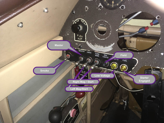
Left side
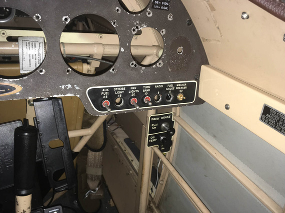
Right side
On the right side, I might clump the switches together, or leave them as on the picture, to "match" the placards (those are left over placards from fuses that were there in the old electrical system). The little brass knob on the right is gonna be panel lighting control pot.
Compass
I am going to replace Pilot's whiskey compass with a vertical card one - yes, I am directionally retarded :) It's not that expensive a mod in the grand scheme of things; and is the only directional instrument available to pilot on this plane (no DG ;) ).
It's a bit taller than the whiskey compass, so I'm playing with different mount locations. I think this is what it will be; with shock isolating rubber pad under the mount where the gap is at the moment.
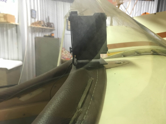
Compass
Fuel Sender Crimps
One of the evenings, I wanted to make sure the Fuel Gauge was still okay (I had a suspicion that it wasn't - turned out to be false).
But first, I wanted to clean up the wiring on the tank sender.
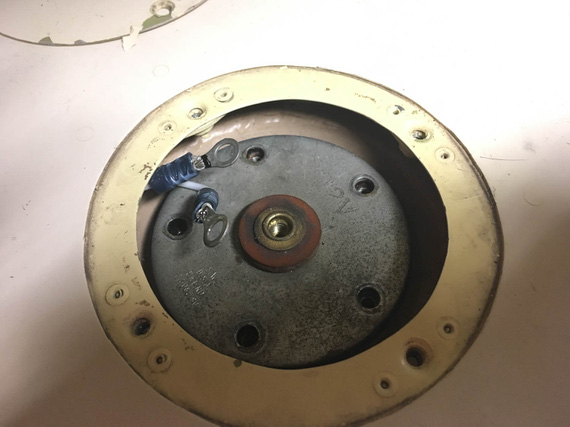
Before
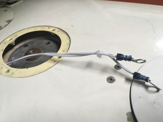
Before
The terminals on it are "automotive" style, without insulation support.
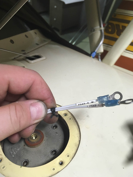
After
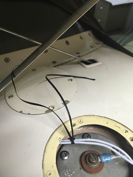
After
There. No zipties, good terminals, and marked :)
Let's make a 360 and get the hell out of here!?!
© Copyright "79FT". All rights reserved. Feel free to cite, but link back to the pages cited.
This website only shows how I did things in my various projects. These pages are for information and personal entertainment only and not to be construed as the only way, or even the perceived correct way of doing things. You are responsible for your own safety and techniques.
