[79FT]: Building Things |
 |
Wiring - Pt II
...part two
| On: | Sep 06, 2020 |
| In: | [Chickenhouse Charger] Electrical Rebuild |
| Time logged: | 18.21 |
| Tags: | 6781G, MA5 Charger, electrical, soldering, fwf, magnetoes, p-lead |
Well, we're continuing happily with wiring over here :).
Wingtips
SkyBeacon and SkySensor were to replace the existing nav lights. Yes, I know, SkySensor is probably a gimmick. But what the hell.
Remo ran nav light wires in a -4 tubing along the front wing spar, using it as kind of a "conduit", exiting the wires around the wingtip, and just soldering them to the nav lights he used. Wires were ~3 ft too long, which is a fine "service whip", but they were just laying on top of the inside of the fabric of the wingtip. There are no access holes on the wingtip, so no way to get in to tie them up.
Oh well. We work with what we have.
I was going to shorten the wires, and because the lights are on the top wing, I didn't want to solder them - I'd be doing it off of a ladder, very near if not on the wing's fabric... lots of things to go wrong.
The other thing I didn't want to happen was to have the connection points between the light's wire pigtails and wires in the wings to "rattle around" the wingtip (with no way of tying them down).
So I had this brilliant idea. The pic is post-realizing the idea was a mistake, with HST cut off....
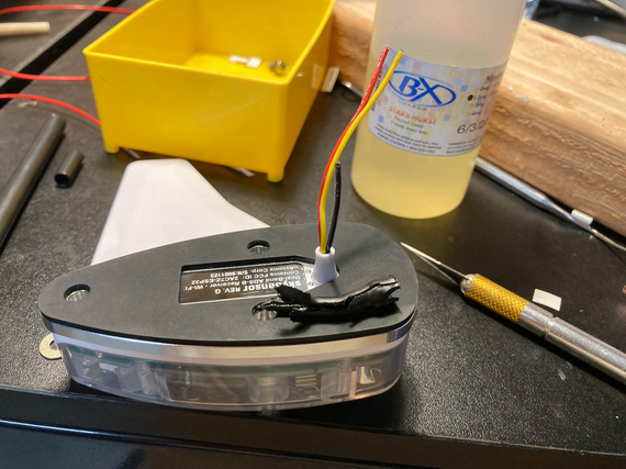
SkySensor, and cut off HST
The lights had this plastic tube coming out thru which the wires were routed. I would shorten the pigtails as much as I could (like on the picture basically), hook'em up to the wing wires with barrel crimps, and put a long piece of my favorite glue-lined SCL tubing over them - with it glueing itself to the plastic tube and to the wires, creating one rigid "tube" coming off of the light...
Boy was that a mistake.
The tubing glued itself to the wires alright - but not to the plastic tube. So the whole thing created a rattly "lever" that would pull the wires thru that tube when vibrated - loading the soldered joints on the PCB of the SkySensor.
Not Good At All.
So that idea had to go to trash, and I had to cut the heatshrink off, carefully, with all the glue, without damaging the wires...
And ended up having to do exactly what I was trying to avoid - having rattling connections between the wing wires and the light, and to solder them. Why solder? Well, because the barrel crimps are heavy, relatively speaking, and I didn't want those heavy "bumps" bouncing around inside the wingtip, even with HST around them.
So, solder.
From the ladder, on top of the wing, covered in fabric.
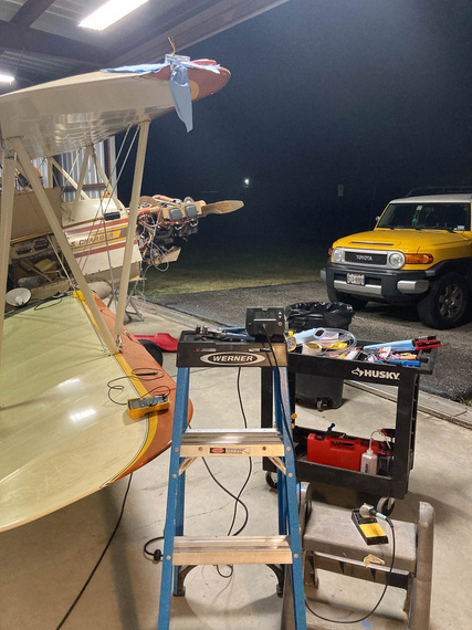
Soldering setup
You can see the heating station on top of the ladder, and the light ready on some layer of paper towels on top of the wings.
As usual, I used the Nuckolls Splice.
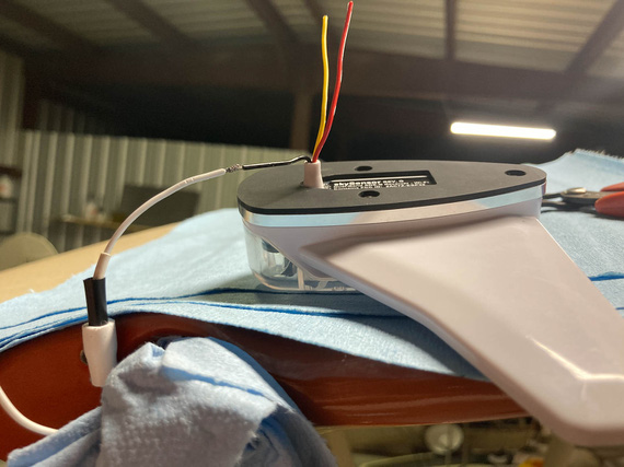
Prepped for soldering
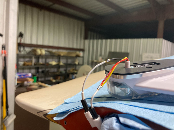
All soldered
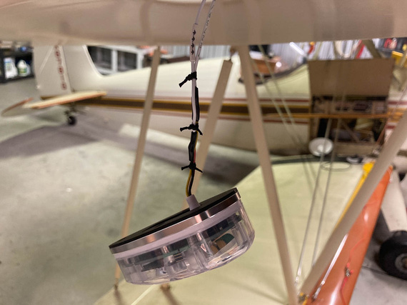
HST, and ties
The other side got the same treatment, and...
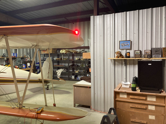
Let there be light!
The other fun part? On the left side, Remo had standard 6-32 tapped holes in whatever the backing of the light socket for the navlight was made out of. I couldn't really see - maybe a nutplate, maybe just tapped sheet metal.
But on the right side, he used sheet metal screws. Which, of course, I didn't know about till I started putting the lights on - because I took apart the left side when checking if SkyBeacon will fit, and assumed the other side would be exactly the same. As usual, rookie mistake. By now, I should know to check everything.
Well, that was a minor delay. Spruce / AN standard doesn't have screws with the right size head (#6 AN screws have heads too large to fit on the SkyBeacon and SkySensor), so McMaster-Carr had to be resorted to to get the right size and length sheet metal screws.
P-Leads
The Charger has the Bendix mags, and the P-lead connectors on those are not ring-terminated; instead, using a "screw in" type deal.
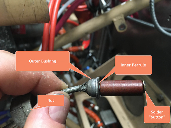
Bendix type p-lead connector - old wire
Basically, the shielded wire goes thru the outer bushing. The ferrule is a "T"-shaped sleeve, and shield get spread out over the "shank" of the T. It's squished between the outer bushing's base and the "flat" of the T of the inner ferrule.
The center wire goes thru an insulating spacer (that brown piece), and thru a washer on the other end - with a "button" of solder built on top of the washer to create a contact point.
The whole contraption gets screwed into the mag's receiving hole with the nut - ferrule rests against the mag's casing, pushing on the insulator and the solder button to contact the contact point inside the mag, while the nut pushes on the outer bushing and clamps the shield between it's base and the inner ferrule.
Now, that works with something like 16GA wire, and it's too big with my small 20GA P-leads. Also, notice how beat up the shield on that setup is? That's the old P-lead.
Folks make adapters for these to go to ring terminals, but they run something like $100 per, which is just silly, so I was determined to make this work.
Here was my idea, and what it looked like on the right mag. Note two P-lead wires - one of them goes to the front cockpit's tach.
We pigtail the shield.
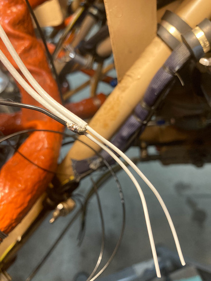
Shield pigtail
That gets heatshrunk - and the diameter is just right to go thru the ID of the ferrule.
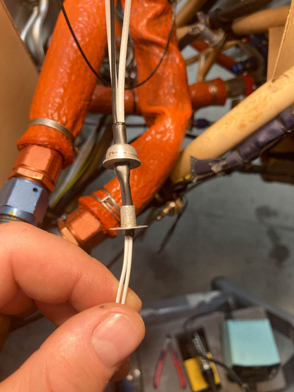
First layer of heatshrink, thru the ferrule
Then, the second layer of heatshrink goes over the ferrule, "sandwiching" it between the two layers of HST.
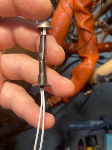
Second layer of heatshrink
And with that, the bushing would slide over the outer heatshrink... but wait. Not so fast! The hole in the bushing's too small, maybe just by .010 too small, to fit over that layer.
Damn.
After playing with various heatshrinks for the outer layer, and trying to slide the bushing on while the HST was hot, I gave up, and...
... just enlarged the hole in the bushing. Yes, I know. The bushing seems to be CAD plated, and I surely took it off (the bushing was magnetic). We'll see how it fares - if I see rust, I can always buy the adapters for silly prices.
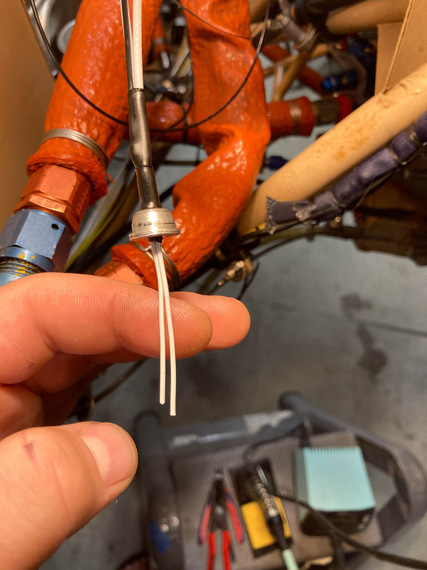
Bushing over ferrule covered in HST
And the rest is easy - fish the center wire (well, wires in this case, but same deal) thru the insulator, washer, and put the solder button on. Except that this is FWF ... hmm...
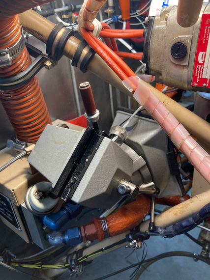
Soldering setup
Another exterme soldering setup? Well, not as much as the wingtips were...
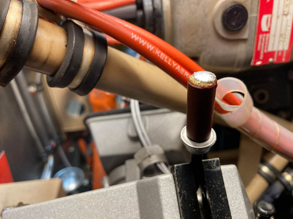
Solder button on and cooling off
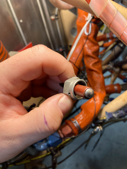
All done
And, screw the whole deal in.
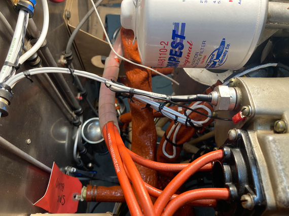
P-lead attached to the mag
FWF, finishing up
And then, the rest of FWF. The only other interesting tidbit was my thinking about the Starter Warning light wire. It's one that goes off of the "I" terminal of the starter contactor - which goes "hot" when the starter contactor closes - to indicate "starter engaged" with a light. The whole shebang is probably superficial, but I convinced myself that I wanted it if for nothing else than to maintain "symmetry" of lights on my panel.
Silly.
Anyway, that wire needed a fuse - though it's an intermittent wire, and I'll admit to thinking about maybe not having a fuse on it, decided to do it, because it wouldn't harm a thing.
Used a 1A "legged" type PCB mount fuse there.
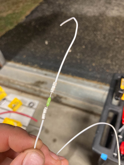
Inline fuse for the "starter warn" wire
The rest of FWF was nothing interesting to write about... Contactors, fuel pump, monitor harness, and the like. Tons of knots.
Got rid of all the remaining zipties and plastic "coils" around the ignition wires, too.
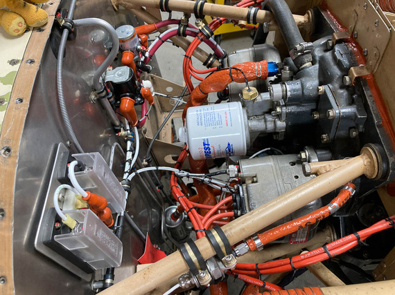
FWF - right side
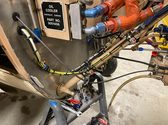
Right side - engine monitor harness
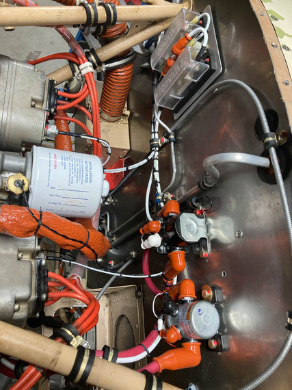
FWF - left side
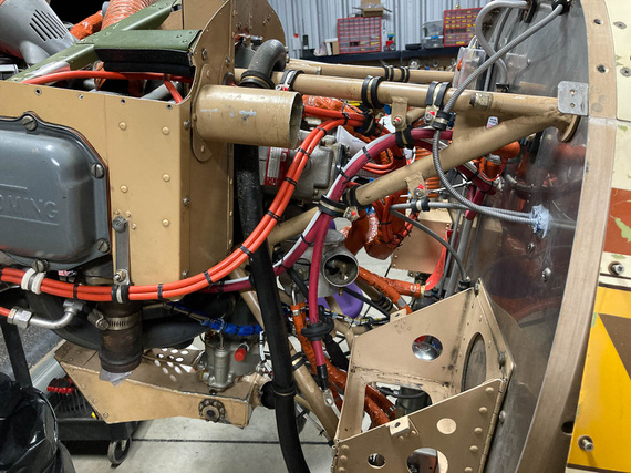
Left side - ignition harness, and battery wires
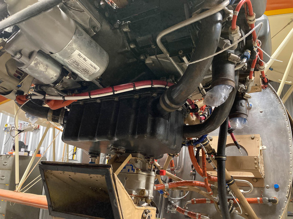
Underside - starter, and alternator wires
Flying is the second greatest thrill known to man…. Landing is the first!
© Copyright "79FT". All rights reserved. Feel free to cite, but link back to the pages cited.
This website only shows how I did things in my various projects. These pages are for information and personal entertainment only and not to be construed as the only way, or even the perceived correct way of doing things. You are responsible for your own safety and techniques.