[79FT]: Building Things |
 |
Drilling the Panel
...misery turned happy times!
| On: | Sep 10, 2019 |
| In: | [Chickenhouse Charger] Electrical Rebuild |
| Time logged: | 5.9 |
| Tags: | 6781G, MA5 Charger, electrical, panel, drilling |
...this is important. Stick a pin in it.
Remo had these nice placards all over the airplane. Professionally done. Very well looking. He probably ordered them somewhere, or used a technique I am not aware of.
These placards are mostly glued on, and do not come off.
How do I know?
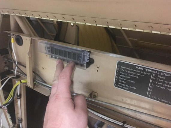
Well, I needed to remove one, in the side conduit. Here it is,..
Placard
..to the right of the future fuse block. It gets in the way - there will be another fuse block there to the right of the one on the picture. And I can't rip it off! I can't remove the conduit to immerse it into whatever solvent will cut the glue without some major surgery, so I guess the new fuse block will go on top of it.
Why am I telling you this?
Ha!
You'll see.
Read on.
Switch Anti-Rotation Holes
You have probably figured by now that I have a taste for misery, and for ranting about how miserable that or this was :). If you read a few notes in this Dear Diary, you will notice a trend - that I tend to come up with ways of making myself aggravated, very consistently and reliably.
Well, this time it was the "anti-rotation" holes for switches in the panel; and the plan was to drill them from the back side of the panel not quite all the way thru (yay, no access and contortionism again!)
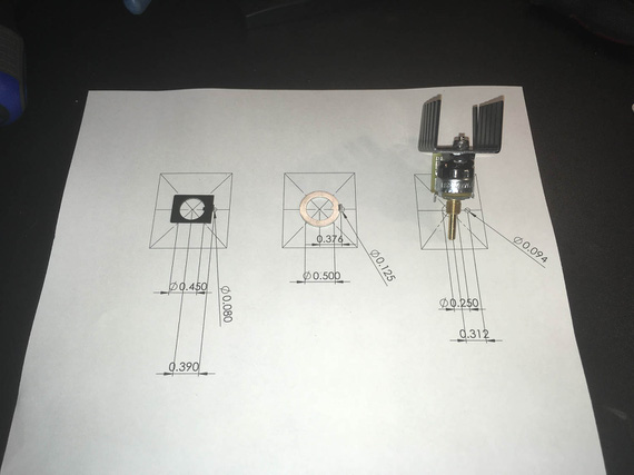
Every switch, circuit breaker, and certainly, a dimmer, comes with a "keyed" washer to prevent it's rotation. That means you're drilling two holes - one for the appliance (switch, or whatever), and the other for the little tab that's on the washer.
Picture explains this better. Here is a little hole template I quickly drew in Solidworks, properly dimensioned, with washers from (left to right) the circuit breaker, switch, and the dimmer.
Holes template
See, Remo didn't have those "secondary" holes on the panel - so I had to drill them (especially for the dimmer).
But wait, you ask. If you drill holes, that will be ugly - a hole next to every switch?
Yup. Aha. Agreed! Though the nuts are supposed to cover them, they, I'm pretty sure, from my testing at least, wouldn't have...
No problem! Remo made the panel from 1/8" thick aluminum, and I needed maybe half that much for the tabs to go in. So the plan was to very carefully drill them just deep enough to house the tabs.
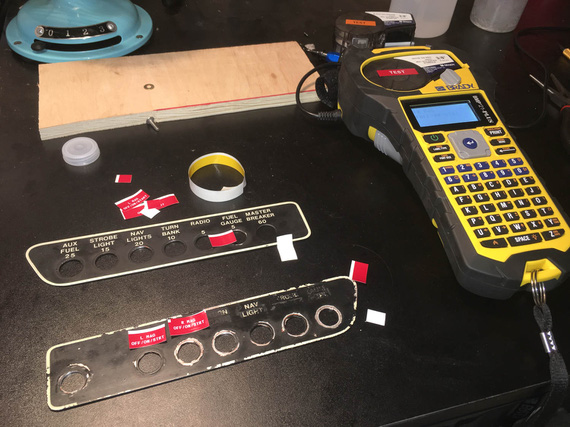
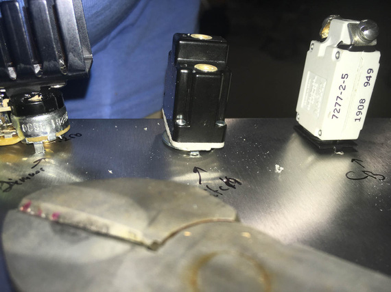
Made me a nice little set of templates...
Templates in the making
...out of a small piece of aluminum, drilled holes using my paper template, and cut them up...
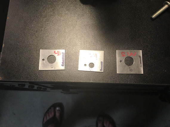
Templates, cut up
...and cleaned up the holes and edges.
The plan was, to put a template like a "washer" around a switch/CB/..., and center punch the secondary, small, hole, thru it. Then, I'll have punch marks to drill, and will have to either get to them from the side of the plane, or, more likely, from the back of the panel while sitting in the seat and not seeing where they are while drilling, using a mirror to position the drill first.
Like I said, I have a taste for misery.
So there we went, punching the back side.
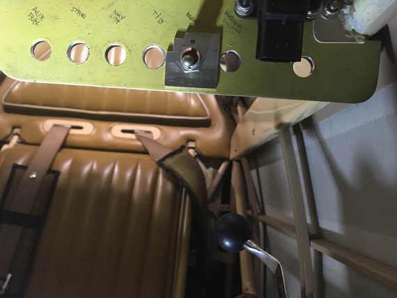
Center-punching on the back side of the panel
Click-clickity-clack.
Cling! Ding! Ding dang dong.. it sounded like a chunk of metal just fell off the plane and dropped on the cockpit floor.
!??!?@??!??! What the h... did I break?!
I crawled out from behind the panel and looked into the cockpit.
On the floor, looking at me, and almost smiling, was...
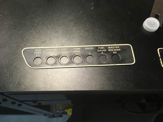
Placard!
...this. Remo's placard that went around the switches. Like so:
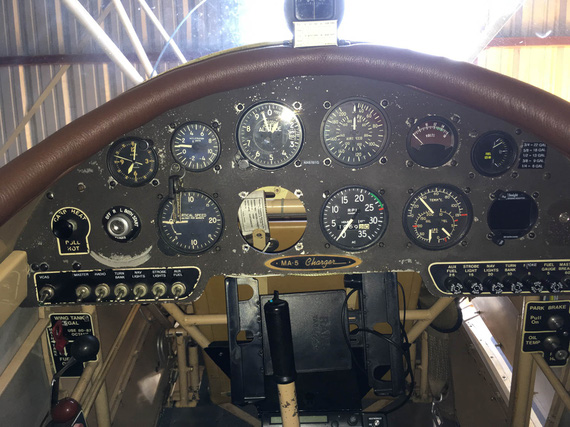
Placards - in place
Wait, wait wait wait. It came off. But it will be held back by the switches' nuts when the switches are in. And.. cover the holes! That means, I don't need to drill the holes from the back side and worry about punching thru (or not going deep enough) - I can comfortably sit in the cockpit and drill them from the front! All the way thru! The placard will cover them! In my search for misery, did I luck out?! :)
In retrospect, this (and the opposite side's) placard were probably not glued. No need - switches' nuts hold them just fine.
They were stuck because Remo probably installed them on top of the paint that didn't fully cure - and it just stuck to the backside of placards over the years, under the pressure from switches' nuts.
I stuck my nail under the opposite side placard, and it came off with a little force.
Ha!
Well, it was smooth sailing from there...
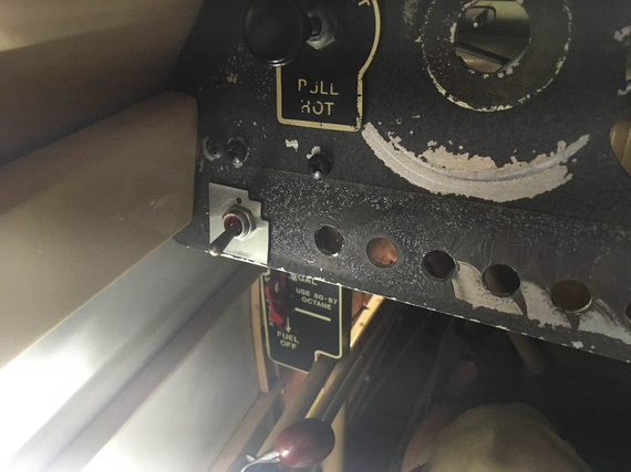
Marking from the front
... relatively speaking, of course. I still had to hold up the vacuum with my knee, and maneuver the sharp drill, making sure to be extra careful not to poke it into anything important (like, fabric on the sides).
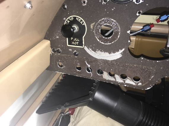
Curlies!
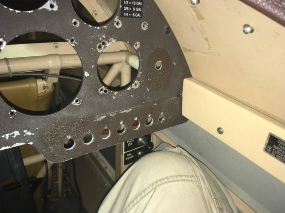
All drilled!
The ones on the corners were annoying; but I already had the drill bit installed into one of my hex drill adapters - so a 90 degree adapter was not an issue. Didn't even need an angle drill.
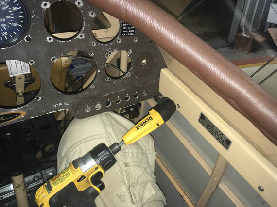
Angle adapter for the side hole
Happy end!
Dimmer Pot
That sucker has 1/4" diameter threads; and all the holes I have in the panel are 1/2... Without some serious bushings, or other mods, or a new hole.. ugh.
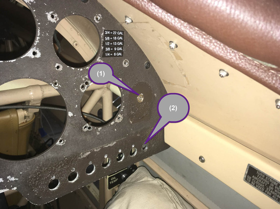
Possible pot locations
I was hoping to stick it into the old "Master Circuit Breaker" hole (marked (2) above), but it was waaaay too big.
Looking around, looking around.... aha! Here's a number 8 or 10 screw plugging a hole! I can enlarge it and we'll be in business! (marked (1)).
Yep. Good luck, buddy. That was an even bigger hole that was plugged with a #8 screw in a countersunk finishing washer... hmmm... maybe that will work out for the pot too?
You know, drilling a #10 countersunk washer to have a 1/4" hole in it is... hard? Annoying? You can't really grip it in any manner without damaging it, you can't hold it in your fingers... I think I lucked out on my third try, with combination of a Unibit and light clamping of that washer in a vice.
With that re-drilled countersunk washer, the pot mounts just fine in hole #2. And #1 got plugged back :).
Compass Mount
Well, after all that excitement compass mount was almost anti climactic. I toyed with the idea of putting it into the panel (and relocating G-meter into a new hole I'd cut around where the ignition switch was - see, after having failed relocating Hobbs there, the idea of still making a bigger hole in the panel keeps nagging me :).
No good. When that much down, too much steel around it confuses the compass to the tune of about 30 degrees... No need to add extra problems in already a magnetically problematic plane.
So, top it was to be. The windshield will get in the way, but I really, really didn't want to take it off (~20 #6 screws and nuts in a tight spot is no fun).
Eyeballed the bracket alignment with the fuselage centerline and put it in the right spot...
Damn! Sharpie's too tall to get in there to mark the holes vertically. "Angle Sharpie Adapter"... hmm..
I know!
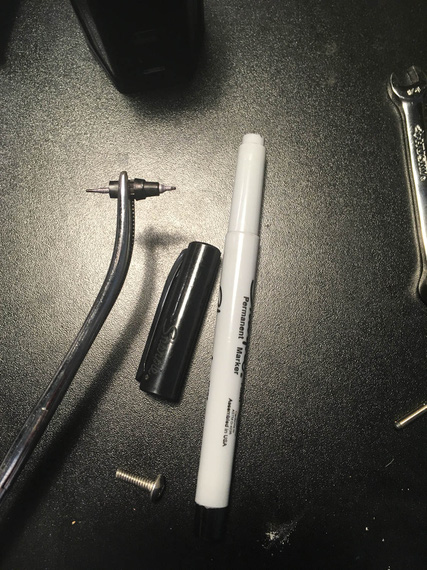
Angle Sharpie Adapter
A bit of disassembly and forceps do the trick ;).
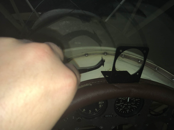
aaaand, mark!
Holes punched and drilled, I added a bit of rubber foam under a portion of the mount to "eat up" uneven surface created by combing...
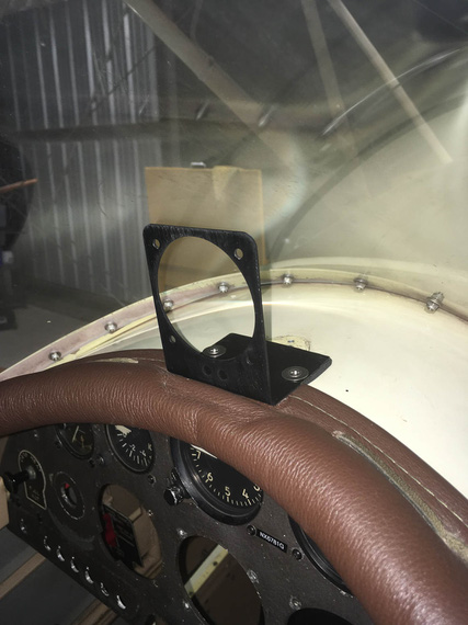
Mount mounted
...and voila...
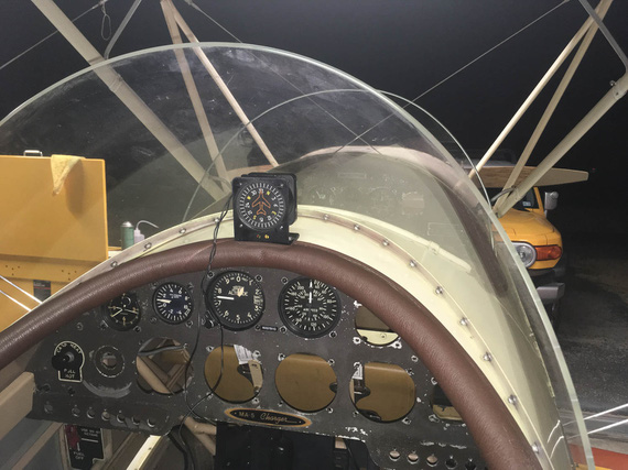
Vertical card compass!
Side note to attentive folks: yes, I know I need brass hardware - those CSK washers and SS CSK screws are temp fasteners I used to test positioning. It will be brass, I promise :).
PPS
Oh, by the way, the best accompaniment (score? ;) ) for working on a biplane is...
... The Chairman, of course!
The three most common phrases in airline aviation are “Was that for us?” “What'd he say?” and “Oh Shit!” Since computers are now involved in flying, a new one has been added: “What's it doing now?"
Up ↑
Alternator Pivot Arm Bracket
lots of grinding
| On: | Aug 31, 2019 |
| In: | [Chickenhouse Charger] Electrical Rebuild |
| Time logged: | 14.5 |
| Tags: | 6781G, MA5 Charger, alternator, 4130, fabrication, drilling, CAD, SWX |
With baffle support bracket done, the next step on the path to alternator happiness was the pivot arm.
The Problem
... was that the default B&C's pivot arm did interfere with the front baffle hookup brackets.
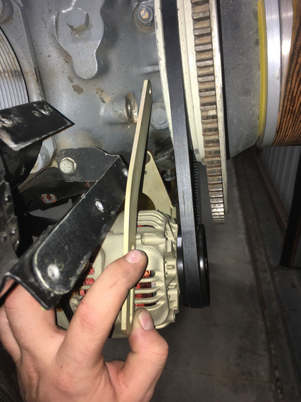
Interference!
That did actually make me pay attention to the very unusual old pivot arm.
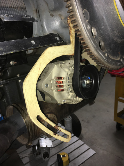
Old one
Nice dogleg, isn't it?
Well, this bracket did not involve any bending, just needed to make the correct one to fit around all the other stuff there on the nose.
Hmm... so how do we do that? Well, first, we need...
The Template
This is not the real template, because (.. read on ;) ). It's the template for the Template.
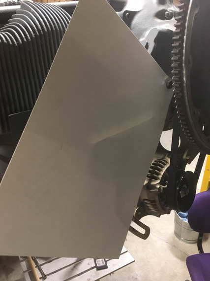
Start with a piece of heavy paper
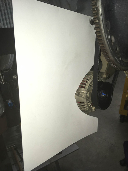
Cut around the alternator
All we need to do with this template is show the location of the hookup hole (top hole, the one that attaches the bracket to the motor); the location of the slot for the alternator to hook up to, and the general outline of the alternator
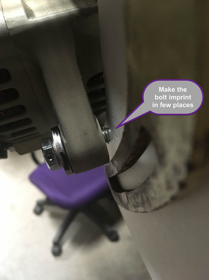
Alternator bolt location is being marked
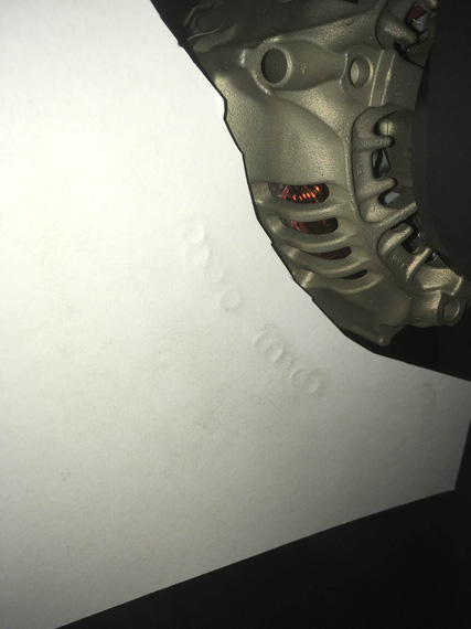
Bolt imprints along the "pivot arc"
..and finally, some more "no go" zones to prevent interference with other brackets there:
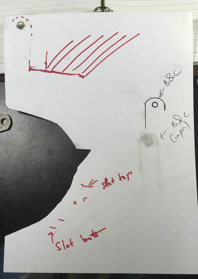
Done!
Notice I also added some "imprints" of the B&C-supplied pivot arm in there, just in case I'd need them.
Okay. I'm lying to you. This template is not the one I used. It was done with the long belt that ended up not working out, so I had to redo the template (thanks God, just the template). The new one was done in the same manner as the one I described above.
Here it is:
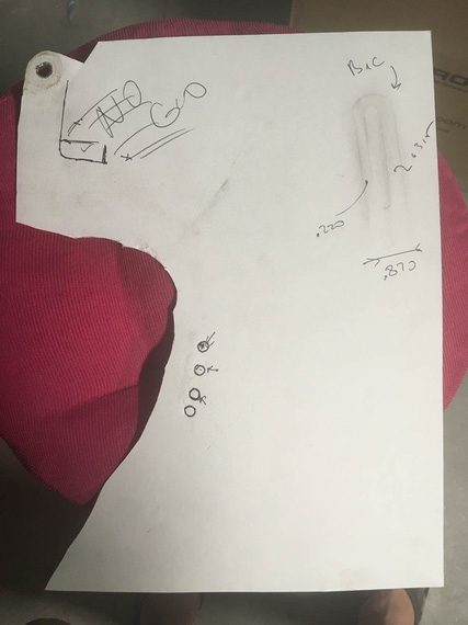
The *actual* template used
Okay. So now, we know critical locations of things and where not to go - so, cue in...
Solidworks!
It's magic, I keep telling people.
So, we take our template, and scan it on a scanner, along with a little metal ruler to give us physical dimensions. Then, we go to Solidworks, start a sketch, and insert the scan as "sketch picture". Using the image of the ruler that was scanned in, we tell Solidworks what "one inch" on this picture is. Boom! The image is now dimensionally accurate.
Then, we start drawing around it.
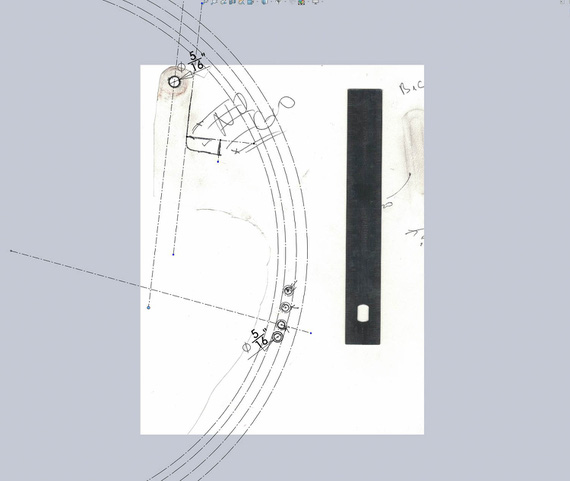
Initial sketch
Above, I positioned the top hole, and the four 5/16" holes around bolt imprints. I then sketched a large circle and made it tangent to three out of four of those holes - it defines the "pivot arc". Then, offsetting it 5/16th gives me the other "side" of the slot; and offsetting it more gives me the "sides" of the bracket in the "pivot arc" area.
I also started sketching the "no go" lines around the top portion of the bracket.
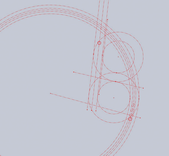
More circles
More circles and lines are added, and off-set. They are not positioned or dimensioned - just made tangent to "no go" lines. You can almost see the outline of the pivot arm, yes? ;)
Now, we take this master sketch; and add arc elements with real lines that we care about.
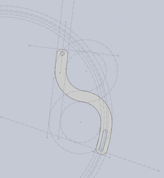
The arm!
Tada! We got the Solidworks Part.
By the way. How do you "measure" the round over of the B&C arm? Radius gauge? Calipers? Hmmm.. Or...
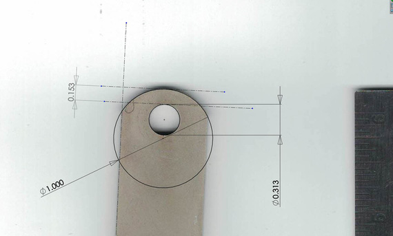
Measuring with Solidworks
Nice, isn't it?
Next, we print the drawing of our new part; making sure our holes' centers are marked (we'll use that later to drill them)
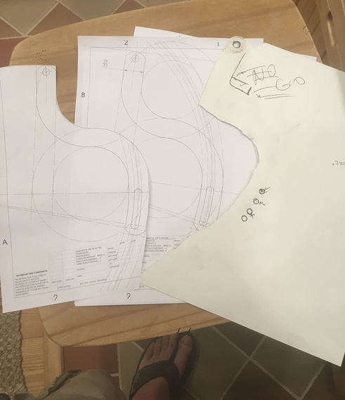
Done!
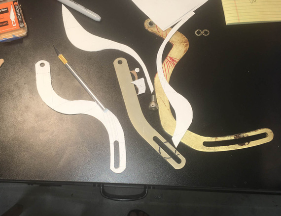
And, we got ourselves the actual template!
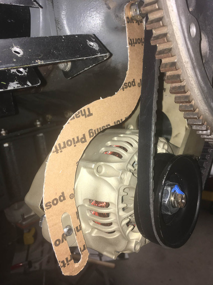
Now, the final test (Many thanks to USPS for providing material for this test)
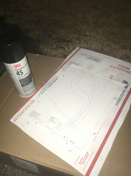
Spray glue and cardboard
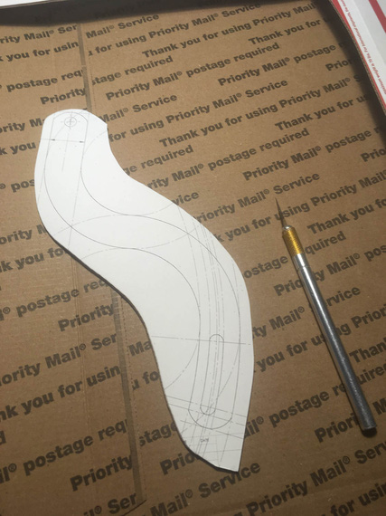
I wish I could cut 1/8" steel with X-Acto...
The mockup
Tadaa!!
Okay, we have the real template now, and we know it'll work. And now, comes...
The Grind
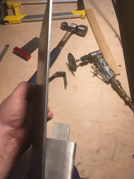
1/8" steel is no joke
Nice little sheet of 1/8" 4130 showed up from Spruce some time earlier... I used spray glue to put the print out of the bracket on top of it.
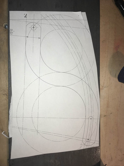
Template on steel
First, all the holes had to be drilled. The drill press I have at the moment is severely underpowered, so I had to step-drill them in four steps.
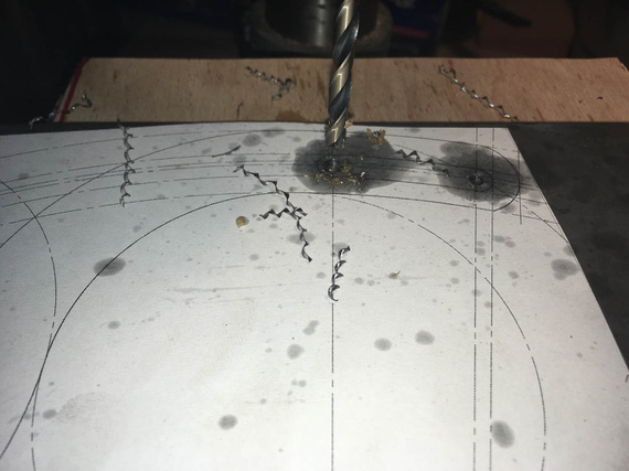
Curlies!
I got to admit, I am starting to become very fond of pretty steel curlies made by nice drill bits.
Also, lesson number one learned: drilling oil (I used TapMagic) gets under the template, and messes up the glue (and unglues it). I need to figure out a better glue.
I drilled the slot's "start" and "end" holes slightly undersized, and reamed the main attachment hole to 5/16ths exactly.
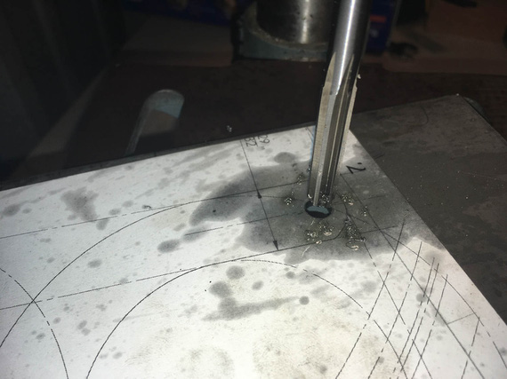
Reamer!
Next, the slot... I rough-drilled small holes around it's perimeter, thinking that a 1/8" shank carbide burr in an air die grinder (basically, Dremel) would work... Ha! It did... for a second ;)
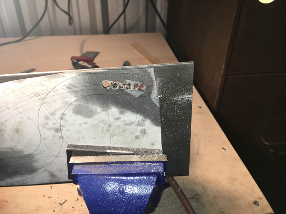
Slot in the making
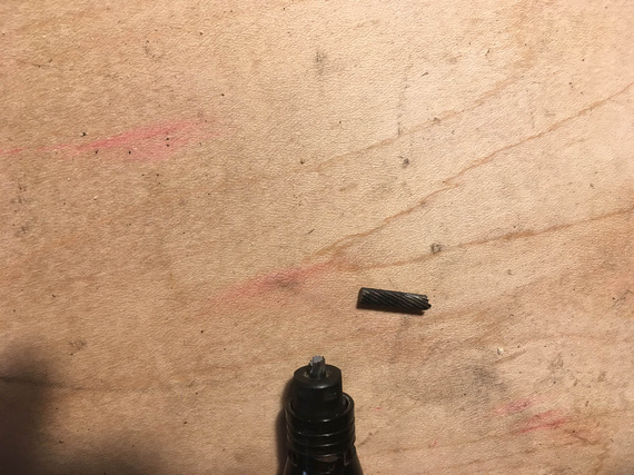
Boo!
Okay, time to go old school... where's that...
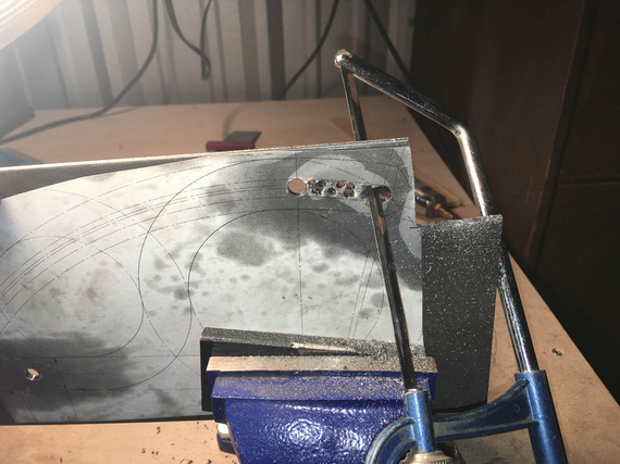
Hacksaw!
I cut it out, and cleaned it out with a bastard file.
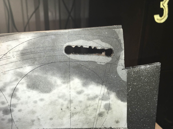
Cut out
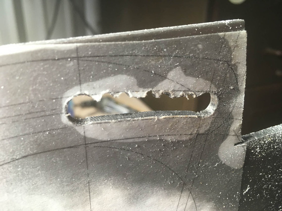
.. and cleaned up
And then, more and more hacksaw...
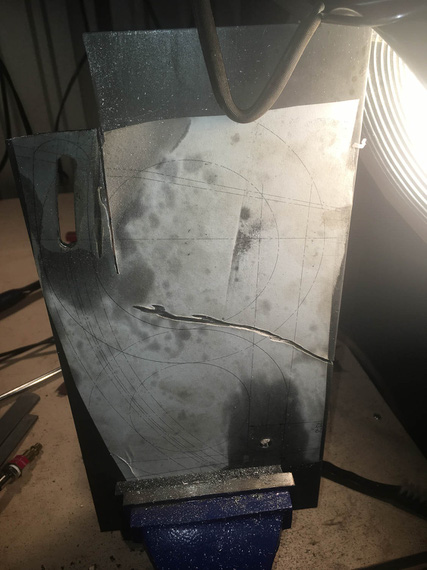
.. my right arm
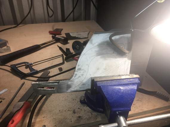
.. is beginning to feel...
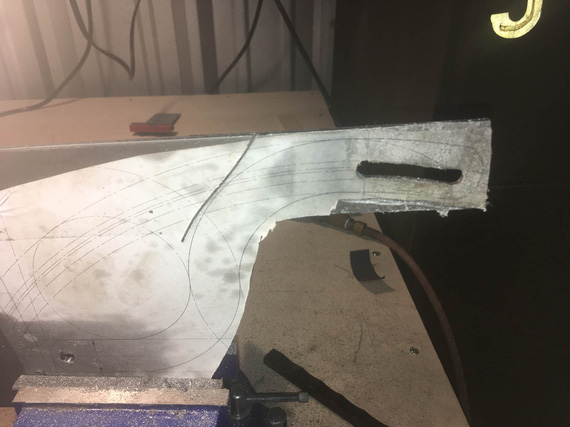
.. it ..
Yeah. The last few inches, I gave up, and used the jig saw. It did cost me 3 blades, but I was too ... done with the hacksaw. I figure, about a blade per 1 inch of cut in 1/8" 4130 with a jigsaw...
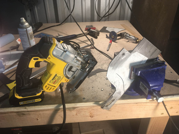
.. gave up.
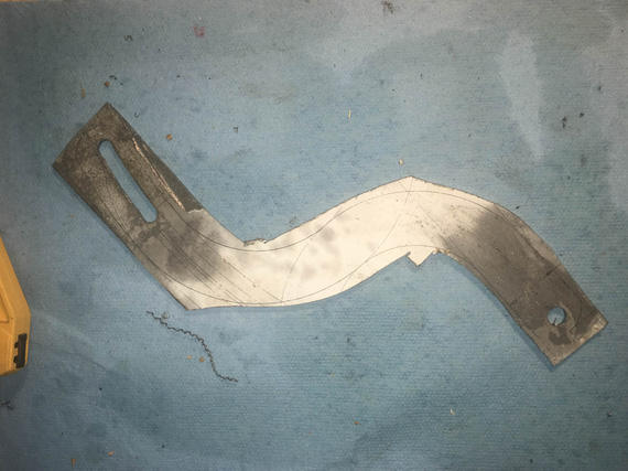
Cutting done.
Looks very ugly, right? Well.... to the grinder!
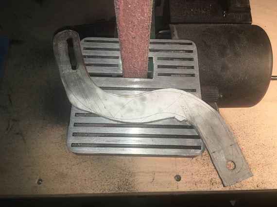
Grind...
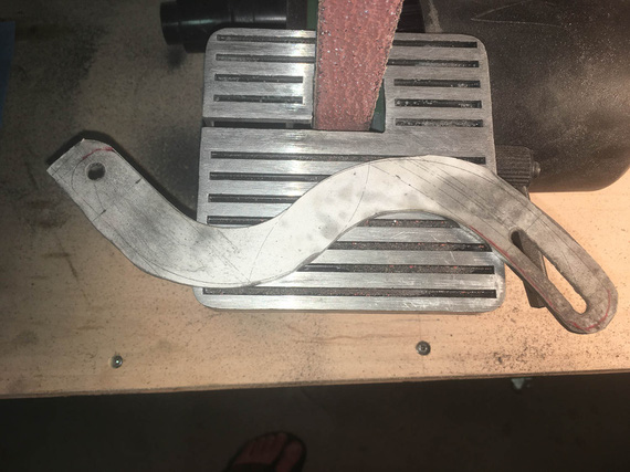
.. grind ..
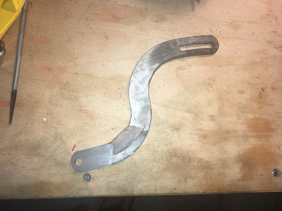
.. grind away ..
Three belts I believe is what it took.
Well, now, the final cleanup on the slot. Yes, Dima, I used the rotary file here :).
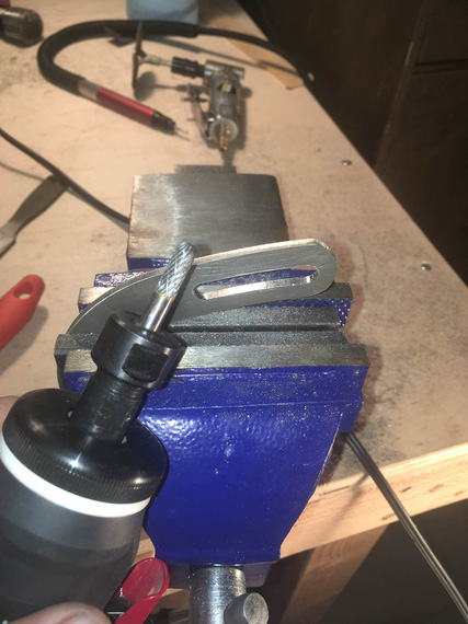
Cleaning up the slot
..and, test fit
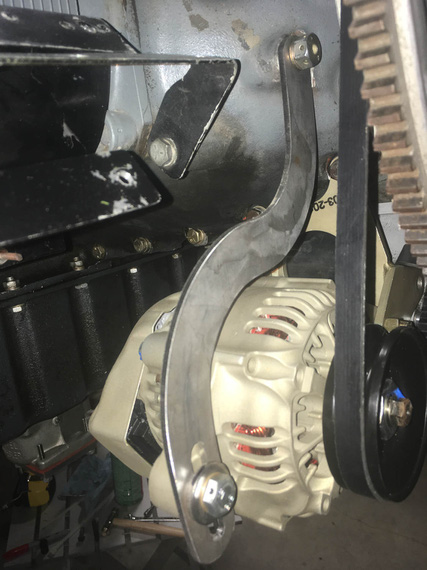
Tadaa!
That was two evenings, folks; but I wasn't done.
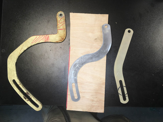
The Three Brackets
Next, I had to prep the edges and sand out all the scratches, and paint. A deburring wheel on a bench grinder helped; and the most nasty marks were filed out and then polished out with the deburring wheel.
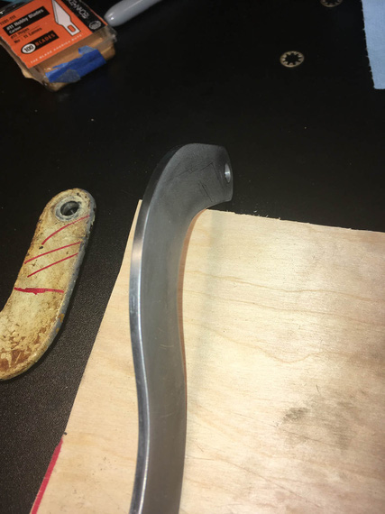
Clean edge
It has to be done because every scratch is a stress riser - on fittings, every edge needs to be rounded over, and polished.
Finally, to....
Paint
Every airplane "paintjob" I've done so far was in my makeshift "paintboots". Like this one.
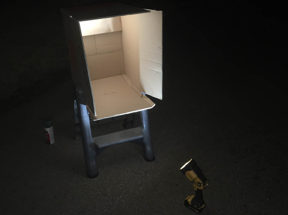
Paintbooth!
I sprayed both the pivot arm, and the baffle support bracket I made earlier, with self-etching primer, and some Rustoleum paint. White will make cracks more visible, if they show up.
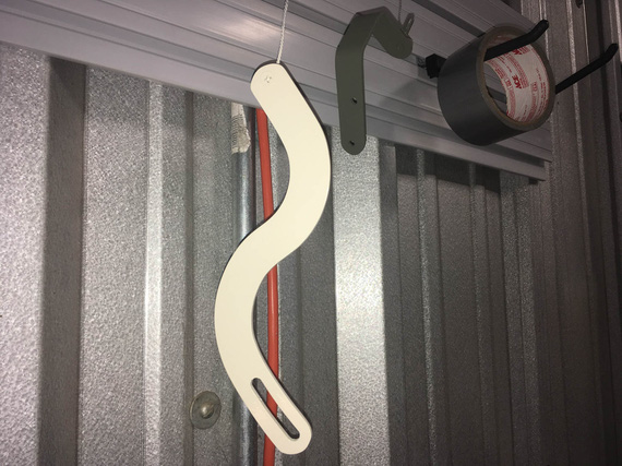
Painted!
So there we go. With this done, I can now install the alternator. Just measly 30 hours to get ready to install the damn alternator! ;)
"Citation 123, if you quit calling me center, I'll quit calling you twin Cessna."
-ORD ATC
© Copyright "79FT". All rights reserved. Feel free to cite, but link back to the pages cited.
This website only shows how I did things in my various projects. These pages are for information and personal entertainment only and not to be construed as the only way, or even the perceived correct way of doing things. You are responsible for your own safety and techniques.
