[79FT]: Building Things |
 |
Wiring - Pt II
...part two
| On: | Sep 06, 2020 |
| In: | [Chickenhouse Charger] Electrical Rebuild |
| Time logged: | 18.21 |
| Tags: | 6781G, MA5 Charger, electrical, soldering, fwf, magnetoes, p-lead |
Well, we're continuing happily with wiring over here :).
Wingtips
SkyBeacon and SkySensor were to replace the existing nav lights. Yes, I know, SkySensor is probably a gimmick. But what the hell.
Remo ran nav light wires in a -4 tubing along the front wing spar, using it as kind of a "conduit", exiting the wires around the wingtip, and just soldering them to the nav lights he used. Wires were ~3 ft too long, which is a fine "service whip", but they were just laying on top of the inside of the fabric of the wingtip. There are no access holes on the wingtip, so no way to get in to tie them up.
Oh well. We work with what we have.
I was going to shorten the wires, and because the lights are on the top wing, I didn't want to solder them - I'd be doing it off of a ladder, very near if not on the wing's fabric... lots of things to go wrong.
The other thing I didn't want to happen was to have the connection points between the light's wire pigtails and wires in the wings to "rattle around" the wingtip (with no way of tying them down).
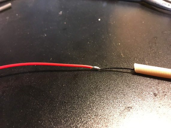
So I had this brilliant idea. The pic is post-realizing the idea was a mistake, with HST cut off....
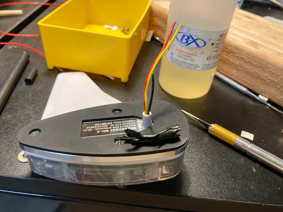
SkySensor, and cut off HST
The lights had this plastic tube coming out thru which the wires were routed. I would shorten the pigtails as much as I could (like on the picture basically), hook'em up to the wing wires with barrel crimps, and put a long piece of my favorite glue-lined SCL tubing over them - with it glueing itself to the plastic tube and to the wires, creating one rigid "tube" coming off of the light...
Boy was that a mistake.
The tubing glued itself to the wires alright - but not to the plastic tube. So the whole thing created a rattly "lever" that would pull the wires thru that tube when vibrated - loading the soldered joints on the PCB of the SkySensor.
Not Good At All.
So that idea had to go to trash, and I had to cut the heatshrink off, carefully, with all the glue, without damaging the wires...
And ended up having to do exactly what I was trying to avoid - having rattling connections between the wing wires and the light, and to solder them. Why solder? Well, because the barrel crimps are heavy, relatively speaking, and I didn't want those heavy "bumps" bouncing around inside the wingtip, even with HST around them.
So, solder.
From the ladder, on top of the wing, covered in fabric.
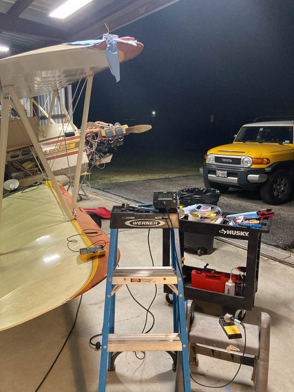
Soldering setup
You can see the heating station on top of the ladder, and the light ready on some layer of paper towels on top of the wings.
As usual, I used the Nuckolls Splice.
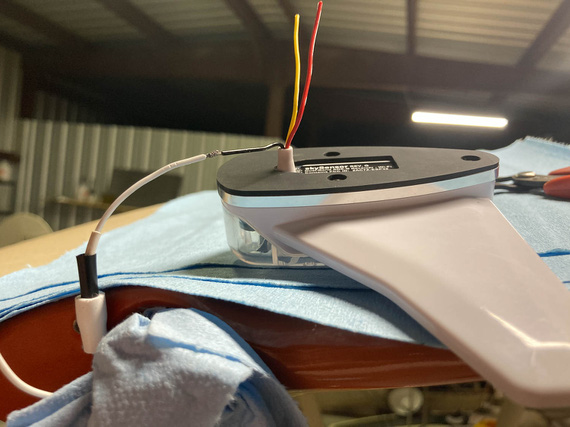
Prepped for soldering
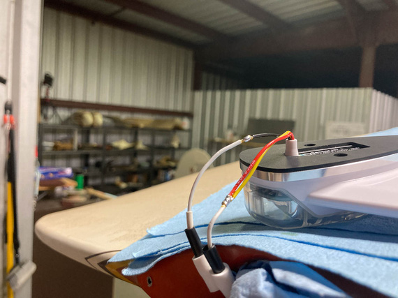
All soldered
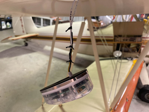
HST, and ties
The other side got the same treatment, and...
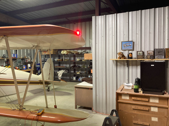
Let there be light!
The other fun part? On the left side, Remo had standard 6-32 tapped holes in whatever the backing of the light socket for the navlight was made out of. I couldn't really see - maybe a nutplate, maybe just tapped sheet metal.
But on the right side, he used sheet metal screws. Which, of course, I didn't know about till I started putting the lights on - because I took apart the left side when checking if SkyBeacon will fit, and assumed the other side would be exactly the same. As usual, rookie mistake. By now, I should know to check everything.
Well, that was a minor delay. Spruce / AN standard doesn't have screws with the right size head (#6 AN screws have heads too large to fit on the SkyBeacon and SkySensor), so McMaster-Carr had to be resorted to to get the right size and length sheet metal screws.
P-Leads
The Charger has the Bendix mags, and the P-lead connectors on those are not ring-terminated; instead, using a "screw in" type deal.
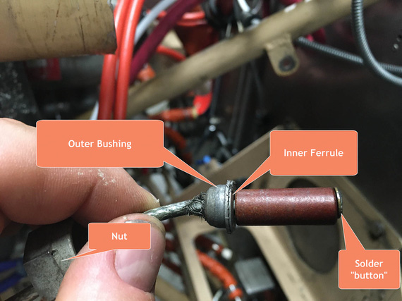
Bendix type p-lead connector - old wire
Basically, the shielded wire goes thru the outer bushing. The ferrule is a "T"-shaped sleeve, and shield get spread out over the "shank" of the T. It's squished between the outer bushing's base and the "flat" of the T of the inner ferrule.
The center wire goes thru an insulating spacer (that brown piece), and thru a washer on the other end - with a "button" of solder built on top of the washer to create a contact point.
The whole contraption gets screwed into the mag's receiving hole with the nut - ferrule rests against the mag's casing, pushing on the insulator and the solder button to contact the contact point inside the mag, while the nut pushes on the outer bushing and clamps the shield between it's base and the inner ferrule.
Now, that works with something like 16GA wire, and it's too big with my small 20GA P-leads. Also, notice how beat up the shield on that setup is? That's the old P-lead.
Folks make adapters for these to go to ring terminals, but they run something like $100 per, which is just silly, so I was determined to make this work.
Here was my idea, and what it looked like on the right mag. Note two P-lead wires - one of them goes to the front cockpit's tach.
We pigtail the shield.
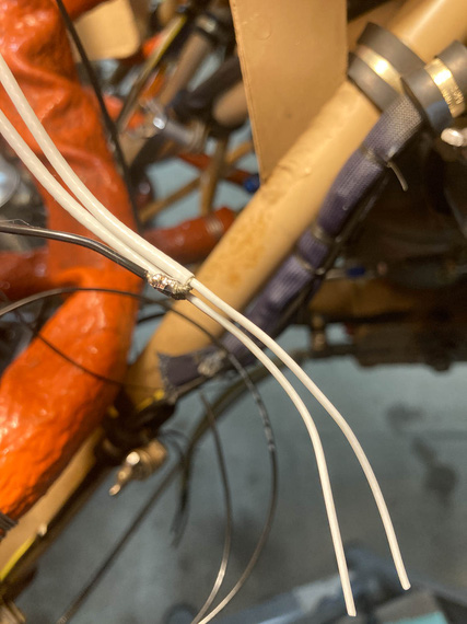
Shield pigtail
That gets heatshrunk - and the diameter is just right to go thru the ID of the ferrule.
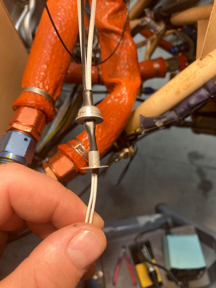
First layer of heatshrink, thru the ferrule
Then, the second layer of heatshrink goes over the ferrule, "sandwiching" it between the two layers of HST.
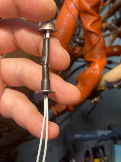
Second layer of heatshrink
And with that, the bushing would slide over the outer heatshrink... but wait. Not so fast! The hole in the bushing's too small, maybe just by .010 too small, to fit over that layer.
Damn.
After playing with various heatshrinks for the outer layer, and trying to slide the bushing on while the HST was hot, I gave up, and...
... just enlarged the hole in the bushing. Yes, I know. The bushing seems to be CAD plated, and I surely took it off (the bushing was magnetic). We'll see how it fares - if I see rust, I can always buy the adapters for silly prices.
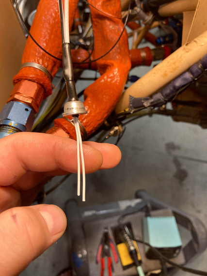
Bushing over ferrule covered in HST
And the rest is easy - fish the center wire (well, wires in this case, but same deal) thru the insulator, washer, and put the solder button on. Except that this is FWF ... hmm...
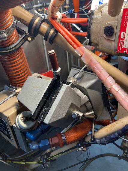
Soldering setup
Another exterme soldering setup? Well, not as much as the wingtips were...
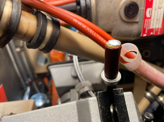
Solder button on and cooling off
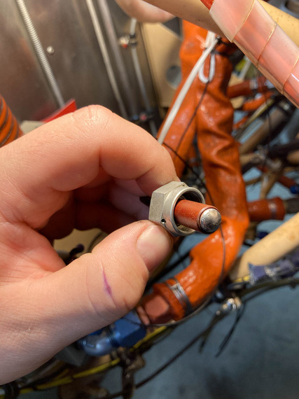
All done
And, screw the whole deal in.
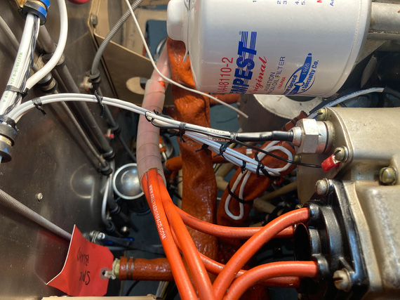
P-lead attached to the mag
FWF, finishing up
And then, the rest of FWF. The only other interesting tidbit was my thinking about the Starter Warning light wire. It's one that goes off of the "I" terminal of the starter contactor - which goes "hot" when the starter contactor closes - to indicate "starter engaged" with a light. The whole shebang is probably superficial, but I convinced myself that I wanted it if for nothing else than to maintain "symmetry" of lights on my panel.
Silly.
Anyway, that wire needed a fuse - though it's an intermittent wire, and I'll admit to thinking about maybe not having a fuse on it, decided to do it, because it wouldn't harm a thing.
Used a 1A "legged" type PCB mount fuse there.
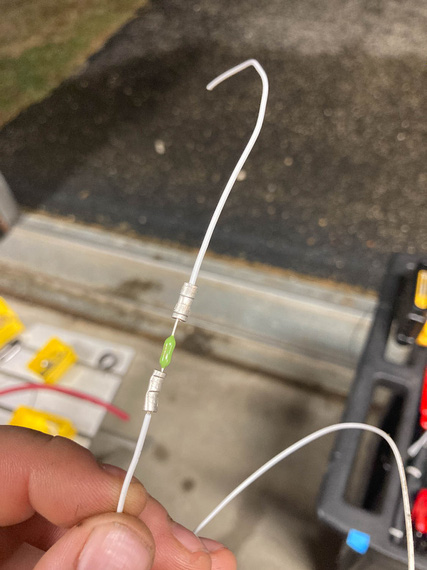
Inline fuse for the "starter warn" wire
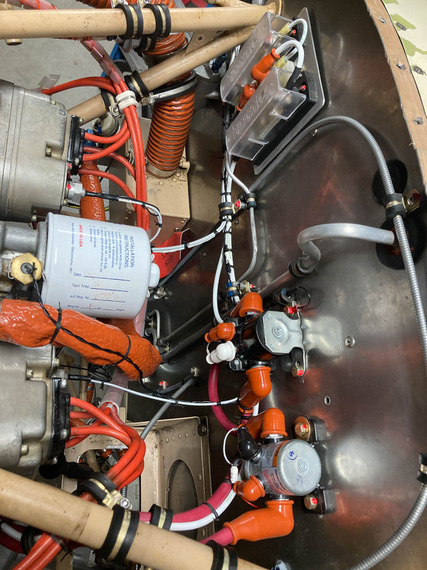
The rest of FWF was nothing interesting to write about... Contactors, fuel pump, monitor harness, and the like. Tons of knots.
Got rid of all the remaining zipties and plastic "coils" around the ignition wires, too.
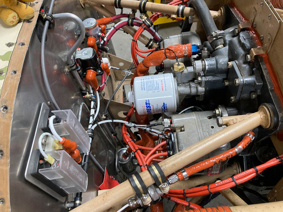
FWF - right side
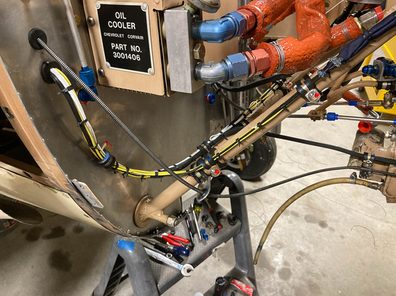
Right side - engine monitor harness
FWF - left side
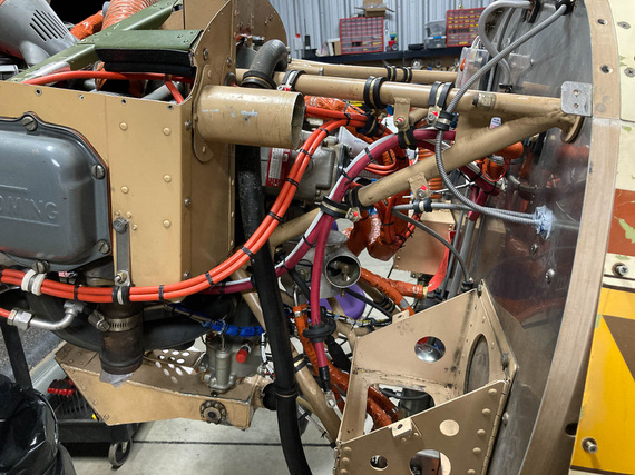
Left side - ignition harness, and battery wires
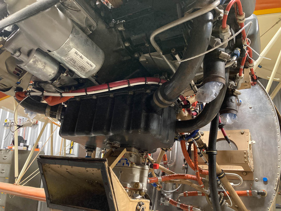
Underside - starter, and alternator wires
Flying is the second greatest thrill known to man…. Landing is the first!
Up ↑
Wiring!
...part one
| On: | Jul 26, 2020 |
| In: | [Chickenhouse Charger] Electrical Rebuild |
| Time logged: | 95.6 |
| Tags: | 6781G, MA5 Charger, electrical, soldering, fwf, panel |
Well, damn. With almost a year (no, more than a year!) of my being a caretaker of the Chickenhouse Charger, I finally was about to actually begin what I have started - which was, putting in my wires.
I decided to start at the switches, and run from the panel forward. Some wires will terminate at the fuse blocks (power feeds), and some will go forward - to the front panel, voltage regulator, and firewall forward.
Then, I was planning to run a few wires backwards - the ones that were pre-terminated on my transducers (fuel, oil pressures, oil temp, and mag pickup for the tach).
Immediately, I will admit: that was a mistake. While the harness turned out alright, it could've been much neater - if I ran in one direction. I could've made sure the whole thing is wire to wire and perfectly clean. So I should've run front to back, because my pre-terminated wires all "started" upfront.
In other words, prop to tail. Well sigh. Next time. On the other hand, this approach would've made terminating switches at the panel a nightmare. That was, initially, the reason why I wanted to start at the panel - so that I'd pre-attach wires to switches, tie them up, and then trim them at the other end.
At any rate.... Shall we?
Prep
Couple things to knock off before I started wiring was to complete the back panel. One thing that was left was the compass correction card bracket. No problem, drilled and tapped a couple holes for #2 brass screws.
Here's Mr. M. installing it:
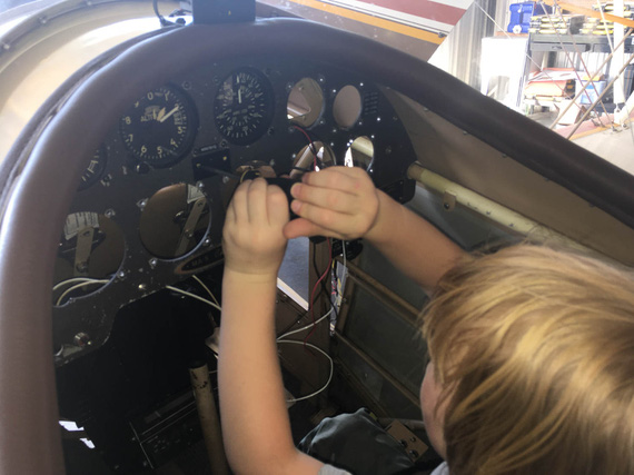
Compass Correction Card Bracket
The other one was the inertia switch for the smoke system. Glenn had it in for "safety": in the event of a shock (crash?) the switch breaks the circuit. I am.. not sure why he would have it, but he had it.
I considered not putting it back in, but what the hell.
Here's the switch:

Shock switch
The problem was, it sat tightly between other switches in the panel. With old layout, that barely worked; but with the new layout, and Honeywell double throw switches, the connector plug was getting in the way. So I had to resort to some vandalism. :)

Removed the connector and the shroud
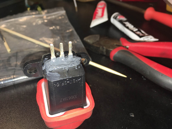
Epoxy around the tabs
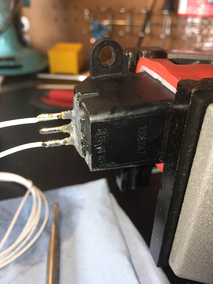
Solder!
And the switch fit nicely. Here it is, tucked between the switches. You can see how that connector would've interfered.

Shock Switch between other switches
The final prep thing was enlarging two holes for ground points to #10 and cleaning the back side up to expose nice shiny aluminum.
Panel
Now ready, I decided to install the switches first, and then wire them from the back. I needed a couple short jumpers though to connect them, and to set up some wires to be the exact length. That'd be impossible with switches installed in the panel (too little access), so I set up an old placard plate, installed switches into it, and worked on those jumpers and terminations on the bench before moving them to the airplane.

Switches on the bench mockup
Here's a couple more pictures of soldering and terminating fun pics:

Warning light socket
(that flux got cleaned off, of course).
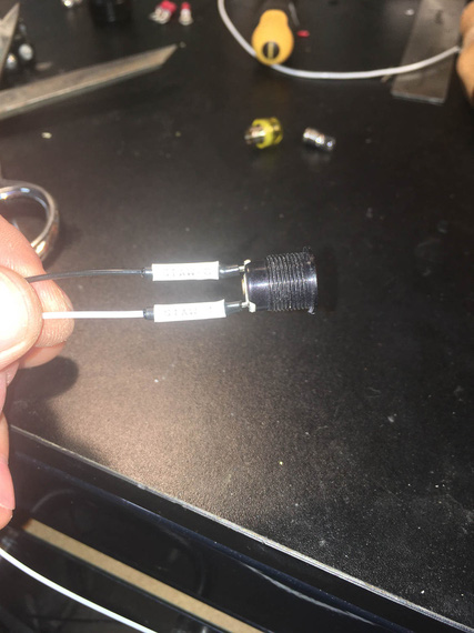
Tagged and shrunk
The heatshrink I'm using for these and in fact all my soldered joints is special strain relief kind with glue in it, specifically, Raychem SCL. It's 3:1 and it is very rigid - almost completely rigid. It definitely adds more support than the typical PIDG crimp used everywhere.
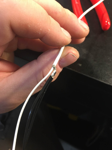
Pigtailing shielded p-lead
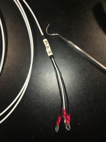
Finished with rings, HST, and tag
And then, switches went in, got tightened and straightened up, and I started running the wires.

Somewhere in the middle of running the wires
I think it happened when I was yet again sitting in the cockpit, clicking the switches and enjoying the very well done Honeywell's action.....
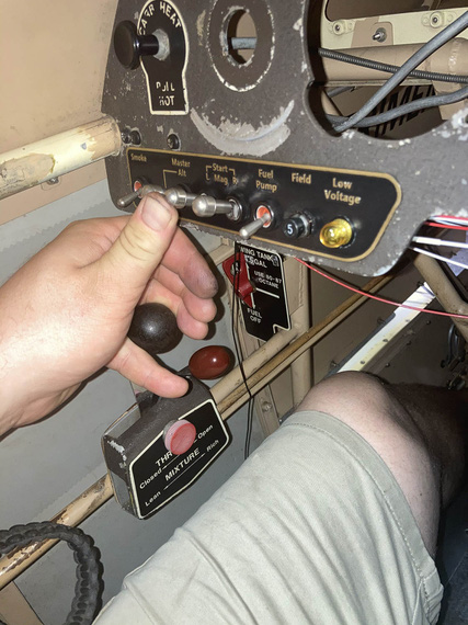
Engine starter engaged position - note that I can hit the starter and hold the throttle with the same hand
...when it dawned on me...
My three most important switches, L and R Mags, and Master, were set up with lockouts - you couldn't turn them on just by clicking them, instead, having to pull the lever first to move it to the "on" position. I mostly did that to protect from accidental too playful a kid in the cockpit.
But they weren't locked out in the "on" position!
Why is that important? Well, the Smoke and the Fuel Pump - the most operated switches on this plane - are right there. Note how their levers are shorter? If I accidentally hit the longer levered Master, or a Mag, switch, that would turn it off - with me potentially shutting down the motor. While a remote possibility, improving the situation would amount to just replacing the switches to the ones with lockouts in both on and off positions.
I don't know how I missed that when designing the original setup...
I decided to do it.
So out came the switches, I had to un-wire the terminals from the back. In went the order for three new switches with now correct lock-outs.
About a week later, I had them, and could proceed.
With left side wired up, I could tie it down. Mind you, access there is tight and from all kinds of weird angles :).
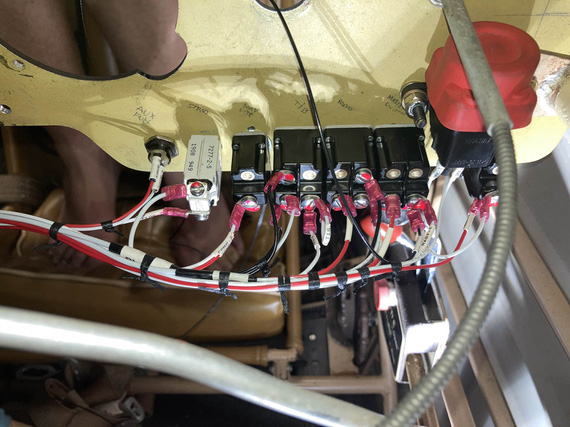
Tying left side
Some of those knots I did from the side. Some I did while sitting in the cockpit, using mirror as reference
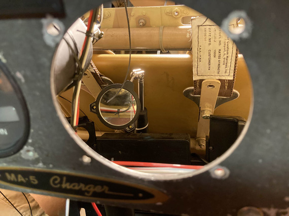
Look in the mirror!
Then, some "extreme soldering" to extend the panel lighting wires, that turned out to be a hair too short.
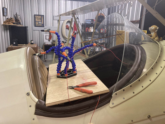
Extreme Soldering
For those lighting wires, and for the turn coordinator, routing took some fiddling with. My initial plan would've had them rubbing against the sides of the gauges, and I decided to bring them "out" and away - that's why I had to extend them, by the way.
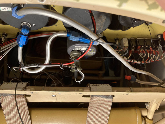
Lighting, and turn coordinator wires, test-tied
Note no padding on that pitot line: this is a temp, "sizing" pass: I am yet to finish assemble the back panel, and will add the right padding then.
The right side of the panel was much easier - it held much smaller, and simpler circuits, for lights and turn and bank.
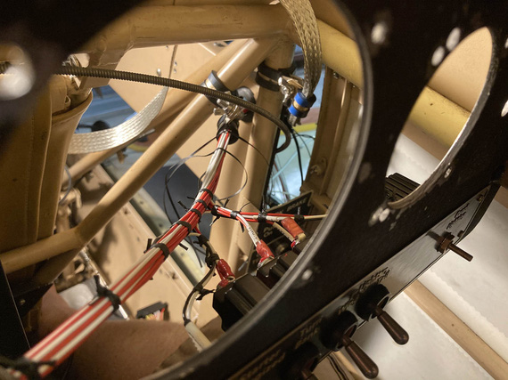
Right side
You can see the beginnings of the ground strap to bond the panel with the "side conduit", holding the fuse blocks and being one of the grounding points. In my original design, I had firewall, motor, "side conduit", and panel, as ground points - all bonded with those straps.
Here's the right side:
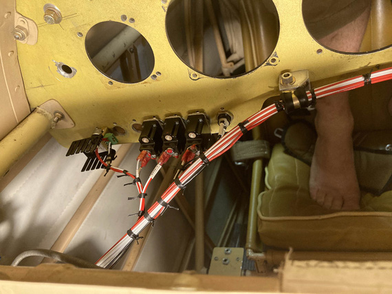
Right side
and the bonding strap
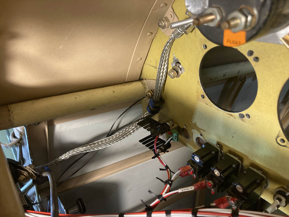
Panel bonding strap
(the bonding strap got enclosed in super flexible heatshrink just for neatness: this is a fit-up picture).
I also had some fun with ADELs right where the wires turn from the "side conduit" towards the panel. I had to clear and negotiate a couple bowdens, and the engine monitor harness was unwieldy.
I think that took a number of hours, just trying various setups, the final one that I really liked was this:
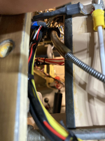
Engine monitor and carb heat bowden.
I replaced all the ugly zipties with lacing, of course :).
Meanwhile, on the outside, to keep the wires nicely separated, I spread them out in kind of a "fan" in the order they ran, back to front:
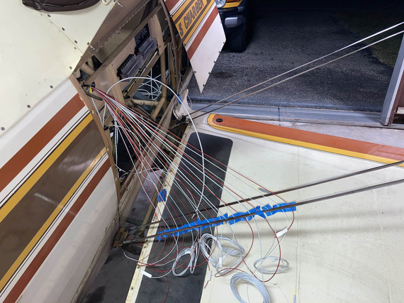
Wire fan
A day later, I replaced the tape with a comb. Yep, a cheapo $1 comb :) Worked out great.
And finally, before committing and continuing, I checked each wire for gauge, and proper circuitry.
Side Contuit, Part I
With all those wires sticking out, it was now time to start figuring out routing in the side conduit. All the wires that had to go forward had, well, to go forward.
After lots of fiddling, I ended up with this:
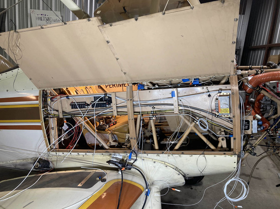
Initial stab at the side conduit routing
I had to clear all the brackets, and other sharp things. Ended up adding a couple more ADELs (and drilling holes in the conduit to accommodate). Also, reused some existing holes, made a few standoffs for ADELs and such.
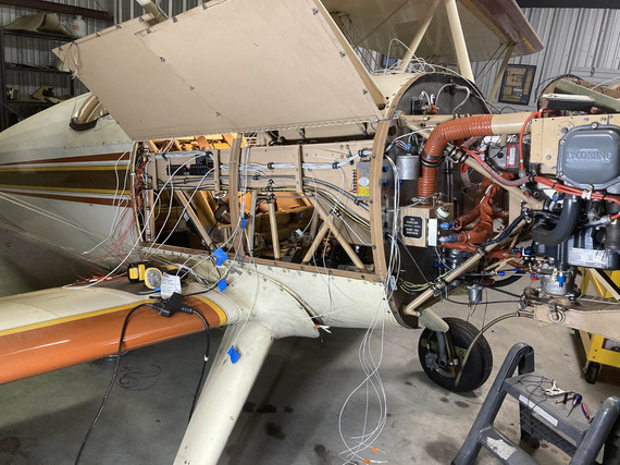
Another angle on the side conduit
And that was it for now. Now, all the other wires needed to join the main harness in the side conduit.
Front Panel
The most interesting piece in it was a Westach tach, that fed directly off of a P-Lead and required a .25A fuse. Glenn used a 1A classic glass fuse, but I decided to do it right. See, the thing is, if it fails "short circuit", that'd turn off the mag - I guess that's why the fuse is in there.
The tach would get another 20GA shielded wire, just like a p-lead, and I decided to join it to right mag's p-lead at the magneto - instead of splicing it into the p-lead running front to back in the side conduit.
But, back to the fuse. I figured, I'd build it into my connector that hooks up to the tach. Then, if blown, the connector could be rebuilt. Yep, it's more annoying than a regular replaceable fuse, but that circuit is not critical, and I had no room for a "regular" fuse block or holder.
So I got me a "legged" .25A fuse with a massive voltage rating (I forget what it was, but definitely above what a mag makes), and hooked it to a regular Molex pin.
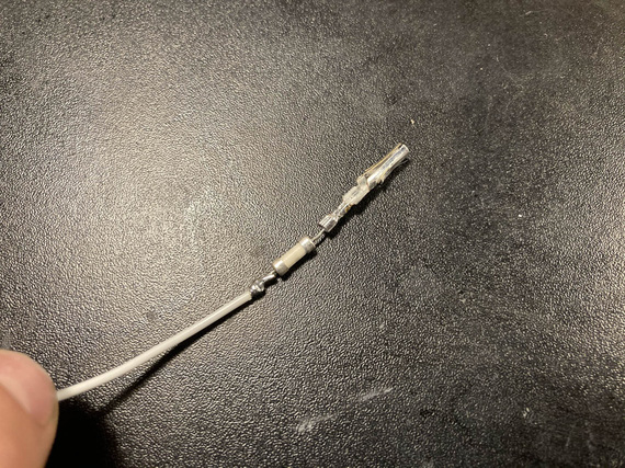
Inline fuse
Finished with SCL, it's encased in a plastic tube and is not moving anywhere. There's two layers there, actually: one around the fuse and the pin, and another around the housing and the inner layer.
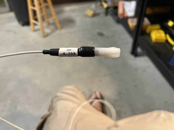
All finished
The final connector got set up like this:
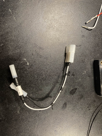
Inline fuse and connector
... and it goes on the tach like this:
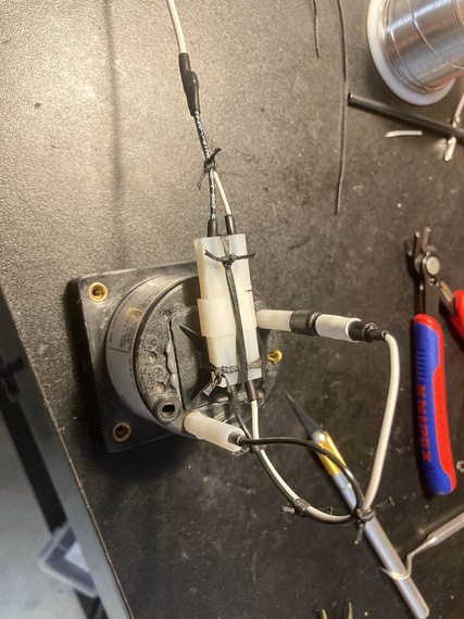
On the tach
The lead is just a regular pigtailed P-lead, of course. Notice how I like using SCL around individual Molex pins for added strain relief - that's because I can't produce good Molex crimps that I like; and I end up post-soldering them in addition to crimping. That strain relief ensures that soldered joint is firmly held immobile. Takes a bit of extra time, but I actually like that better than straight Molex crimps.
The rest of the front panel wasn't interesting, just annoying. There's only three circuits there: nav lights wires from the left wing run along the back of the panel to the right side where the conduit is, and then there's hobbs and tach, and that's it. It was just very annoying: with very little access, not being able to see things, and, being in the front hole, having to climb out and in every time I needed a tool I forgot to put close (when in the back hole, I can roll up a cart to it and have all my tools there).
Mirror was absolutely required.
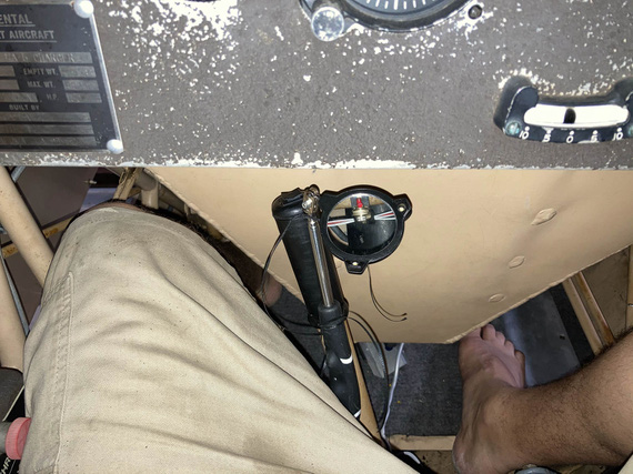
The only way to see things
I will admit to asking my dentist right around this time if he had a trick up his sleeve for this kind of mirror work. Of course, he said. Practice. Lots and lots of it.
Okay, so the front panel got done, and it's wires merged with the main harness.
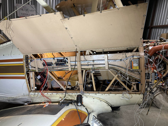
Front panel sub-harness joining the main
There, see, it's that small bundle going up and disappearing from view right in the middle of the "conduit"? That's the front panel sub-bundle.
Firewall Forward
The final set of wires to join the main harness were all the wires coming from the firewall side - mainly, transducers and other instrumentation wires, but also a couple wires for the voltage regulator.
This was precisely when I realized the mistake I talked about in the beginning - and ended up with less neat, and more tortured harness. Oh well.
I started up front, trimming and terminating my fat wires for the starter and alternator B-feed. Some more extreme soldering (to cap them), this time with a torch.
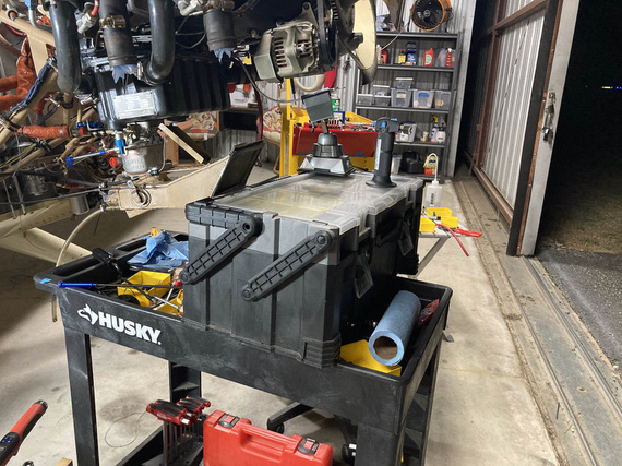
More extreme soldering
I tied up, and clamped the fat bundle to the motor: and apparently, didn't take a single picture.
Then, I had to figure out the diode for the Starter contactor - first of, it needed longer leads. There, instead of soldering, I used small barrel crimps from Molex along with heatshrink (I do use them where soldering is impractical, and I decided not to have soldered joints FWF).

Diode with leads

And all enclosed
And then, a simple ADEL to hook it up and hold it
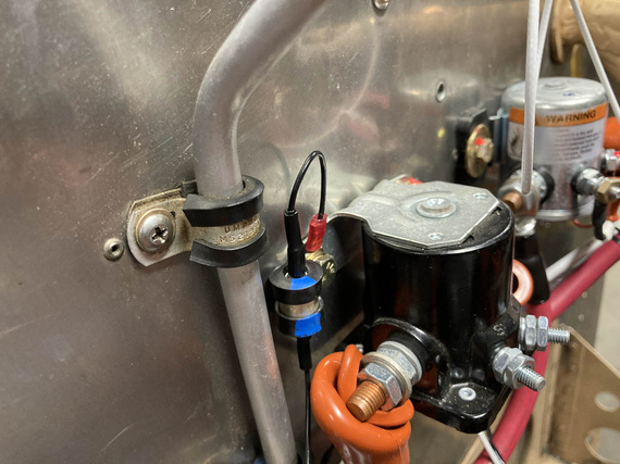
Diode all hooked up
And then, the ammeter shunt, and the sense wires. Those needed fuselinks - in liew of an in-line fuse. Simpler, and cleaner this way.
I tested them a while back, and am confident they'll work.
First, we take a wire 4 "gauge steps" thinner than the fused one (so 24GA for 20GA fused, etc). That goes into the "source" terminal.
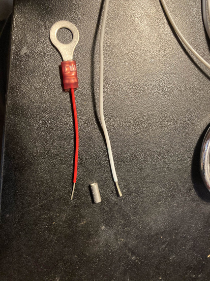
Beginning of the fuselink
Then, we hook it up.
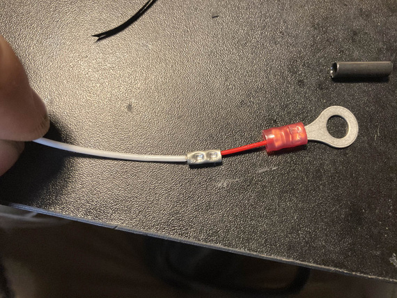
Hooked up to the protected wire
Then, some heatshrink over the splice, for strain relief.
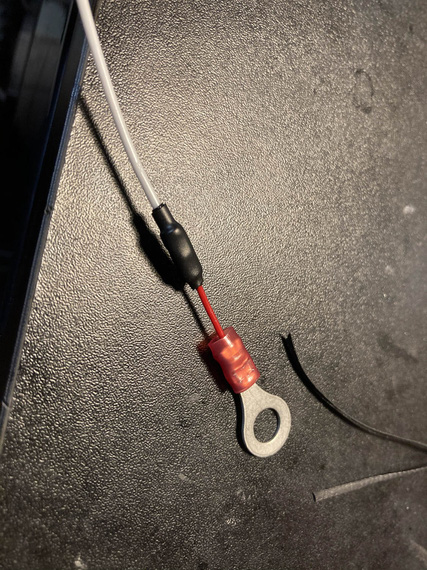
HST
Then, a bit of fiberglass sleeve to contain the "fire" when (and if) it does it's job, as in, burns thru the thinner wire that acts as a fuse in case of a short.
A bit of marking too. And a "cap"
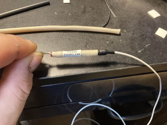
Capped and labeled
And finally, a couple knots to hold the sleeve better.
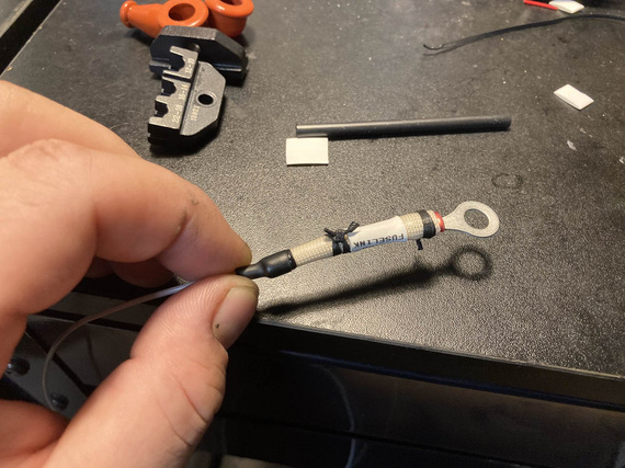
And laced
And finally, I finish installed all the engine transducers: pressures, and oil temp; and routed all their wires back into the side conduit and thru it back to the cockpit, adding them to the main harness. And that was that, for now - I plan to terminate them later.
Tail Light
I got rid of the belly strobe on the plane, because it was too heavy and too.. useless. Wingtip lights are gonna be the SkyBeacon and SkySensor from uAvionix (my ADSB mandate compliance :) ), and they have strobes: but they're not visible from the back. So I decided to replace the tail nav light with an LED nav/strobe.
Problem number one: no ground wire going to the tail light. For whatever reason, Remo decided to basically use the fact that the tail light is hooked up to the rudder with a pair of screws thru sheet metal of the rear rudder bow... I don't even want to begin to think what the ground path would be: hinges? control cables?
So, I needed a second wire.
Problem number two: it had to be one neat cable, and it had to be of a smallish diameter (Remo had an old 20GA wire, which is thicker than modern 20GA tefzel wire).
I decided to use a chunk of 20GA shielded - same ones I used for p-leads. Technically I guess you're not supposed to do that, but it's very far from all the antennas and I'm crossing my fingers that it won't create too much problems. Thickness was spot on.
So, I soldered the new piece to the old wire, and fished it thru using old wire as a pull. That part was scary - if that didn't work, I would've had to cut holes in the rudder to get a new wire thru.
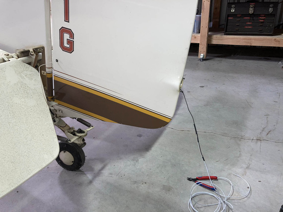
Fishing a new wire thru
The tail light shipped with a small Molex. Why not?
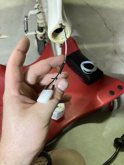
Connector terminated
The other end went onto the light, and everything got hooked up
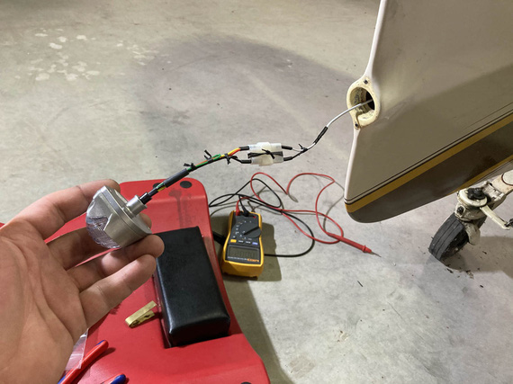
All hooked up!
On the other end (on the tail fin side) the wire went into a hole on the inspection cover, and had to join the wire coming from the front. And I had to have the ground there. You can see that area right behind the elevator on the "fishing wire thru" picture.
Problem number three: nothing to hook up the ground to in that area. The only option I figured out was to use one of the rivnuts that are attached to the tabs welded to the frame, hoping that there's no corrosion there between the aluminum rivnut and steel fuselage. I figured I'd use a way too long a screw thru one of the rivnuts when attaching that inspection cover, and then pull the ring terminal onto it, and secure it against the back side of the rivnut with a nut and a washer. Ugly? Yes; but I didn't have any more options. Really, the right way to do that would be to run two wires from the pilot panel all the way back, but.. I'd have to start cutting fabric for that.
So, I attached the positive to the wire that was already there, terminated my ground, hooked everything up, hooked up some power, and...
Nothing.
A bit of debugging showed that... ground was the problem. Damn! I picked the wrong rivnut, I guess - it had corrosion. The one right on the other side though showed the right voltage when measured against the positive lead, so I just moved everything to the other side, and...
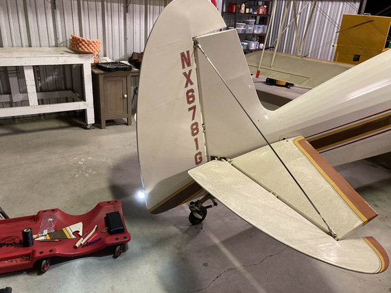
Let there be light!
Side Conduit, Part II
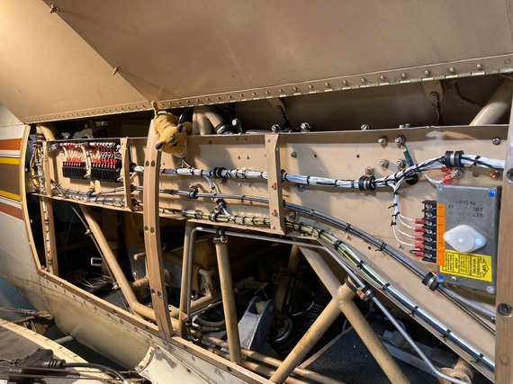
At this point, the main harness looked something like this:

Main harness: complete, but not terminated
Now was the time to go thru it, cockpit to firewall, and terminate all the fuseblocks, and tie and zip everything up.
First, conduit, cockpit side. Lots of crossing things, lots of padding for bowdens where they cross the wires (I used the right sized vinyl tubing from my local friendly Aerospace Depot, and lacing to tie it).
Engine monitor harness got covered in tube for quite a distance - there was no way to keep it off and not rubbing on the conduit.
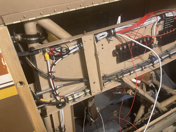
Cockpid side conduit
Fuse blocks got their placards. No, Mr. D., I am not doing brass placards again!
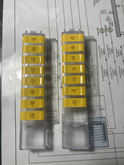
Fuse block covers placards
And then, slowly, methodically, every power wire got it's ring terminal. I added a bit of a "service loop" and used a ruler to try to keep each next wire exactly the necessary amount longer to reach the next terminal screw... Didn't work out too well, but close enough.
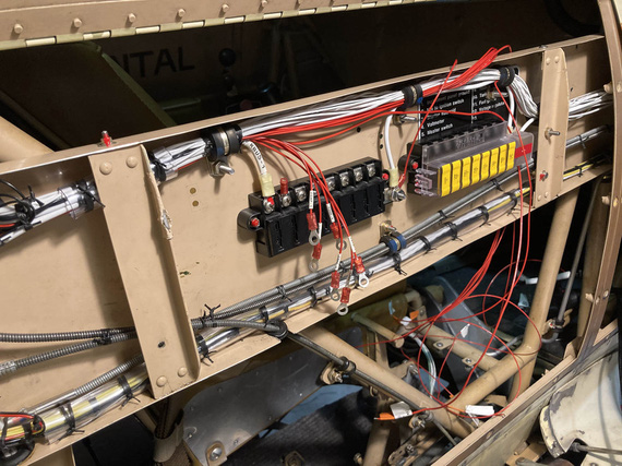
Rings!
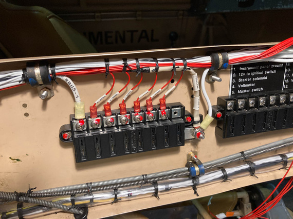
Tied up and hooked up
Another side got the same treatment, and then...
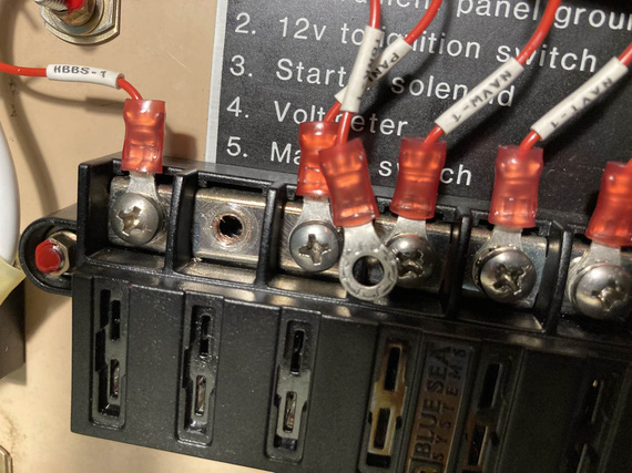
?!?!?!
Did I just strip a terminal block hole?? Yep. I did. I blamed a bad block and definitely, positively, absolutely not my overtorquing the screw. Nope. No overtorquing. For sure!
So, had to get a new block. They're $35 so I figured I won't try to repair this hole to use an upsized screw....I'd spend more money on shipping small-headed #10 screws (the screws in the terminals are #8 but with small "oval" rather than "pan" aviation style head, so I'd have to get me some decent screws from McMaster.. by the time I'd be done, it'd be close to those $35).
So, fuseblocks. From there, it was just turning everything pretty.
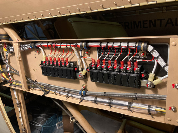
Both fuseblocks done and tied
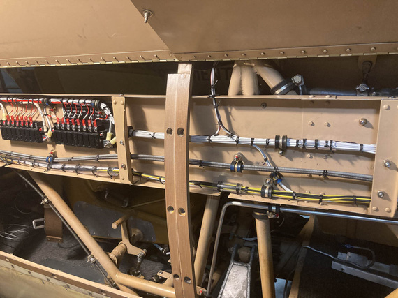
Mid section
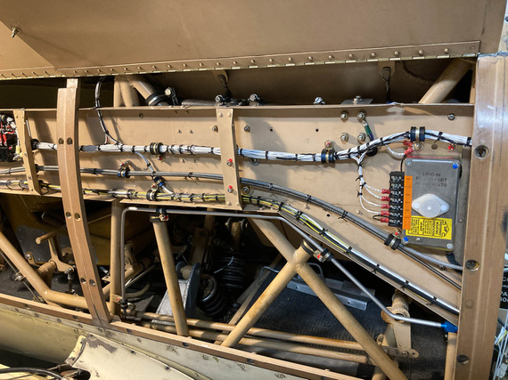
Voltage regulator
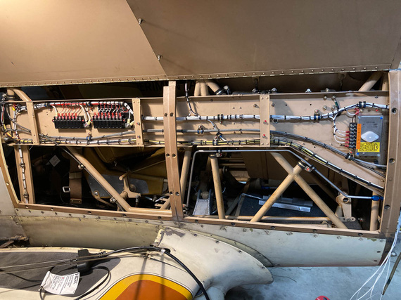
The whole thing
Sorry, couldn't resist doing a "before" picture.
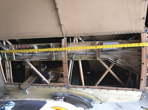
Before
Jack likes this!
It at first you don't succeed, well, so much for skydiving.
Up ↑
Solder, and Good Crimps
... the answer is NOT solder?!
| On: | Oct 08, 2019 |
| In: | [Chickenhouse Charger] Electrical Rebuild |
| Time logged: | 5.5 |
| Tags: | tools, electrical, soldering |
A while back, I wrote a note on my failures at getting good crimps with the hydraulic crimper I had.
My conclusion then was, "solder".
Well, I tried :). I had to make a little bonding strap, maybe 5 inches long.
First time, I cowboyed it - just stuck the strap into the terminal, and soldered away.
In. My. Face.
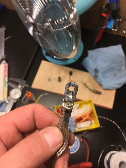
Ugly!
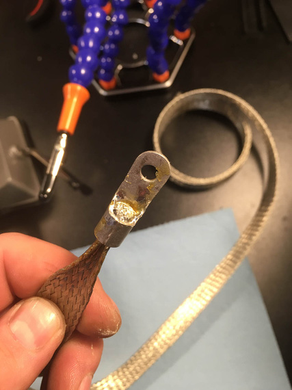
Second try.. I think
I was soldering, de-soldering, soldering again, etc. Trying different positions, and different heating methods (butane torch worked best).
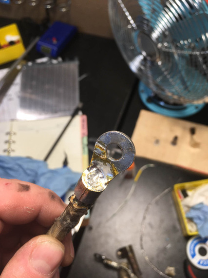
One of the better ones
I eventually started using the "wedge" trick - to wedge a piece of thick wire in between the wire strands, so that the wire gets packed into the barrel of the terminal.
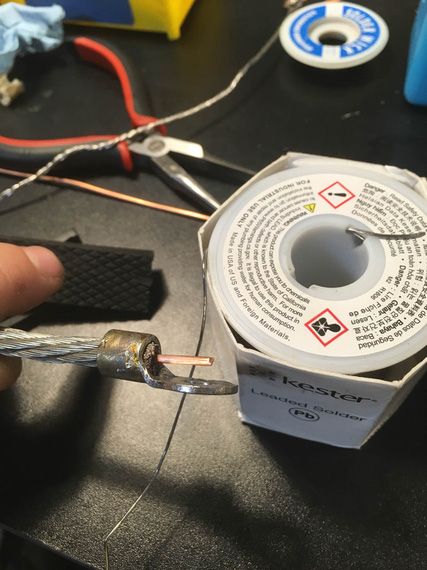
Wedge
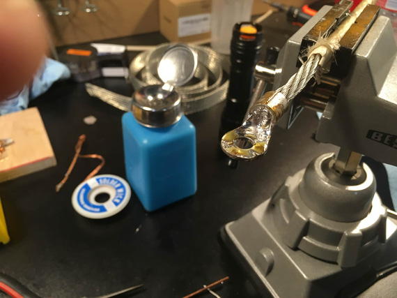
All that yellow crust is rosin flux
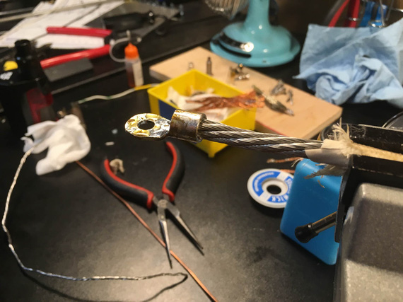
Back side
My main problem was, I was trying to prevent solder wicking as much as I could. And I couldn't. It would make 1 inch or more of the wire perceivably "crusty", and I still won't have the barrel filled in. Remember, I was trying to make a small, short grounding strap, that had to be flexible to bend almost 180 degrees. I was trying to achieve a "crimp quality" break between solid metal and strands, and could not.
When I started thinking about it like that, I realized that what I'm trying to do is likely impossible.
Solder will wick - you can control how much with technique and practice, but you can't prevent it. So my current thinking is, if you solder your large lugs, be ready to support first few inches of wire really well, so that that "crusty" portion of it doesn't move.
So, I tried to Hail Mary the crimps again. Previously, I had them just damn ugly (I linked the article above).
I got a small anvil tool (the kind you insert the barrel of the terminal and whack a pin with a hammer) from Spruce. Thought, 25 bucks was worth a try.
Those crimps were even uglier. I don't know what I expected - I guess that was an act of desperation? I didn't even take a single picture.
But then... I had a minor epiphany.
With the Harbor Freight Crimper, dies are not properly ground for wire sizes. But. But.
Just like with hammering, we can crimp progressively until we "flow" all the strands and the barrel into one solid piece!
Here's the approach (okay, this is the final procedure, first try did not include turning - but I did it (admittedly, accidentally), and liked the results a lot).
- Given wire gauge of, say, 6
- Use die 2 sizes up - so, die marked for #2 wire
- Put the wire in the terminal. Start by squeezing the terminal turned 90 degrees (so "side to side" rather then "top to bottom"). Just give it a gentle oval shape
- Now, turn it 90 degrees and squeeze until the jaws close
- At this point, you will have a somewhat undercrimped joint, as I described in my notes on the crimper; but it's shape will be a perfect hex.
- Now, go 1 size "down" (so, dies marked for #4 wire). Squeeze.
- Stop when you feel it's done shrinking.
Results?
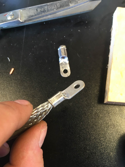
Pretty!
Pretty, ain't she? And, no "wings".
If you don't do the turning trick, it'll still be pretty; but with just a whiff of those "wings" present:
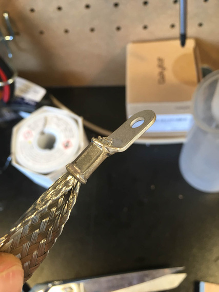
Pretty!
All all this was what... five and a half hours?
Well, I guess, that's the "education" part of the "Education and Recreation" charter of E/AB aviation ;).
Don't drop the aircraft in order to fly the microphone.
Up ↑
Electrical Disassembly
...fun with wires
| On: | Jul 01, 2019 |
| In: | [Chickenhouse Charger] Electrical Rebuild |
| Time logged: | 13.1 |
| Tags: | 6781G, MA5 Charger, electrical, soldering |
Well, all the electrical on the Charger is disassembled now. I logged about 24 hours doing it.
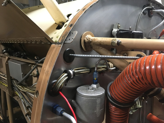
Firewall wire harness, looking into the side conduit
I have started with wires on the terminal block and in the side channel, and was moving back and forth between various locations - get bored in one, move on to the next.
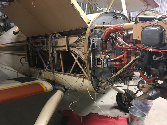
The disassembly has begun!
In the side conduit, going on the right side of the plane to the back cockpit, I was slowly removing the wires, and the oil and fuel pressure lines.
Had to be careful to mark the wires I wanted to keep - all the wires going to the lights, and some instruments in the front and back.
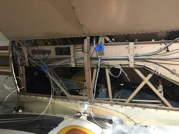
Wire by wire...
I would cut them off, and pull them out one by one.
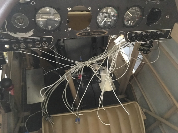
Behind the panel is a rat's nest!
I pulled the mechanical tach and it's cable, and the oil temp and pressure and fuel pressure gauge.
By the way, the oil temp gauge was unpowered! And still ran on a thermocouple - but it's huge, to generate enough power to move the needle.
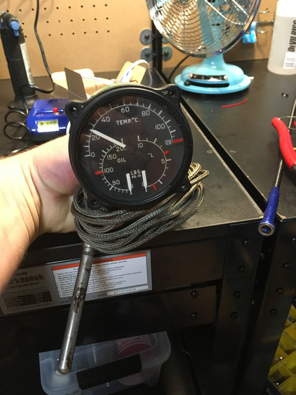
Old school!
Heck, I'm keeping it as my IHT Gauge!!! (Internal Hangar Temperature, that is). It just looks too cool.
Eventually, all the wires were gone from there, aside from the ones I'm keeping; and the ones I'm keeping got temporarily marked.
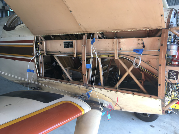
All done!
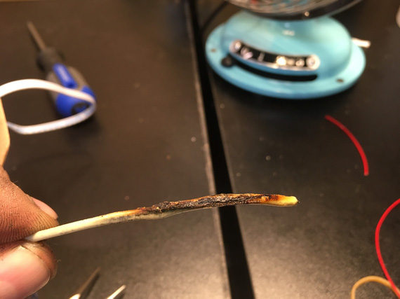
By the way, I found a burnt wire! Was one of the unfused wires going to the voltage regulator.
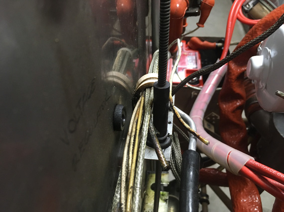
Burnt wire - can you see it?
I cut off the burnt chunk.
Front
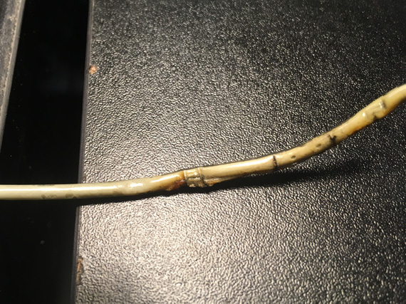
Back
See those little "boil bubbles" on the back side? Insulation was super brittle, and just a minor twist cracked it open.
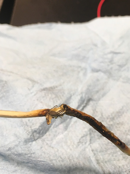
Cracked
Meanwhile, behind the panel were a couple of soldered things - with wires unsupported. One of them was the master switch, the other one was this weird resistor in the voltage regulator circuit where the low voltage alarm light was supposed to be.. go figure.
But look at the solder joints:
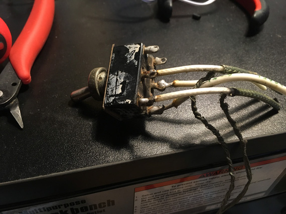
Master Switch
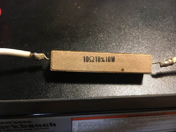
Resistor
Notice, they were not done very carefully (especially the ones on the Master Switch). Flux was not cleaned. But! The joints look, and are, solid. They are almost 40 years old.
I think I am officially now in the "no soldering on airplanes is an old wife's tale" camp.
At some point, I decided to take a break, and try on the new Voltage Regulator I'm planning on installing.
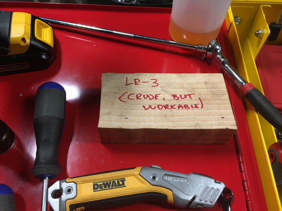
....it's not up to scale, and I did not have the time to paint it...
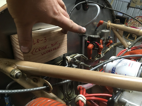
FWF location
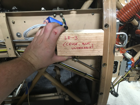
Side Conduit location
I'm thinking I'm gonna mount it in that conduit on the side. It'll stay cooler, and generally be tidier. I'll use the space occupied by the old voltage regulator for my current limiters and the ammeter shunt, though still need to think a bit more about placement. Maybe those will go somewhere else, too.
By the way, the old voltage regulator in all it's glory:
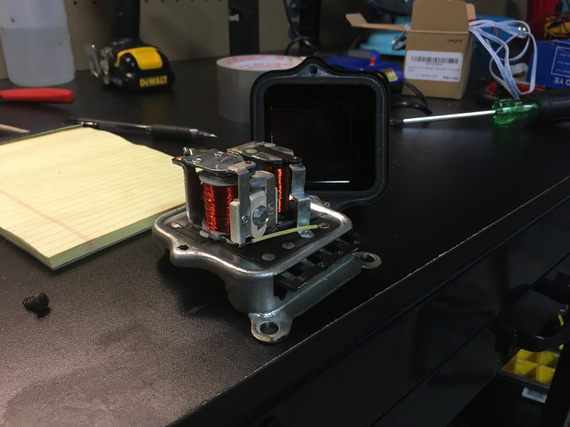
A Mechanical Switching Voltage Regulator
I also completely removed the strobe - I'll be replacing nav lights with SkyBeacon/SkySensor; which will cover my blinking needs.
Wanna see a couple old electrolytic caps? The strobe power supply still worked, by the way!
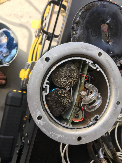
The Strobe power supply and bulb
I have disassembled the charging and starting circuits completely, too. Since I'm redoing everything anyway, adding better wires, and new terminals would not add too much expense, and be good for the system. I also want to modify how battery is grounded.
Found this next to the Master Contactor
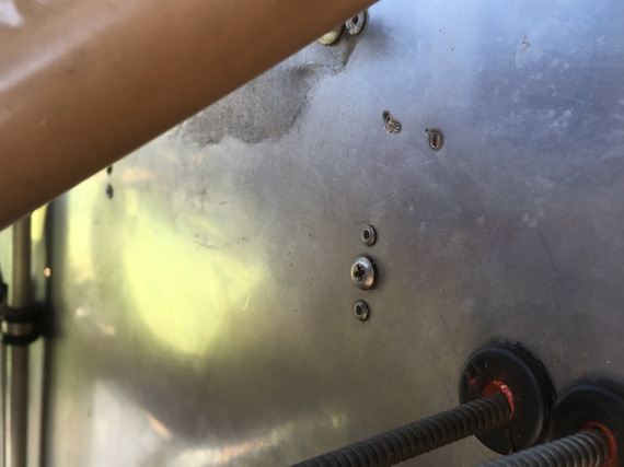
Accidental welding on firewall
Do you see it? Two spots, above the screw? Someone didn't disconnect the cable when working on her! :). (And, no, that wasn't me)
And finally, here's how almost the entirety of electrical system looks like.
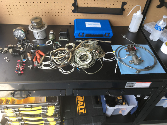
Most of the electrical of a biplane
Some swithces, some fuses, some wire, and that's it!
Try to keep the number of your landings equal to the number of your takeoffs.
Up ↑
Wire Markings, Fuselinks, Load Measurements, and Turn-and-Slip
tested fuselinks, measured loads, removed and diagnosed turn-and-slip indicator
| On: | Jun 18, 2019 |
| In: | [Chickenhouse Charger] Electrical Rebuild |
| Time logged: | 6.5 |
| Tags: | 6781G, MA5 Charger, electrical, experiments, research, instruments, soldering |
Finally, doing some actual work on the airplane, and having fun! And I decided to start logging time.. because, why not!
Wire Marking
I like marked wires. I used to be a networking guy, and I was very meticulous about marking every single wire in my cabinets, so that I knew exactly what was plugged in where.
It took a bit of upfront time, but saved a bunch of it later on.
So naturally, I was planning to do the same on the Charger, and, more importantly, make it look professional.
Thanks to living in this day and age, that is simple. No, I'm not gonna pay someone to laser etch my wires - that's a cop out :). It's like paying someone to paint your plane.
Instead, I have researched and found a perfect label maker - Brady BMP21 (not including a link here because it will probably go dead after some time... just search for it). This thing has 3:1 heatshrink tube cartridges.
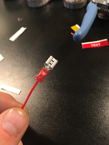
The proverbial coupon
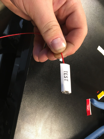
Prior to shrinking
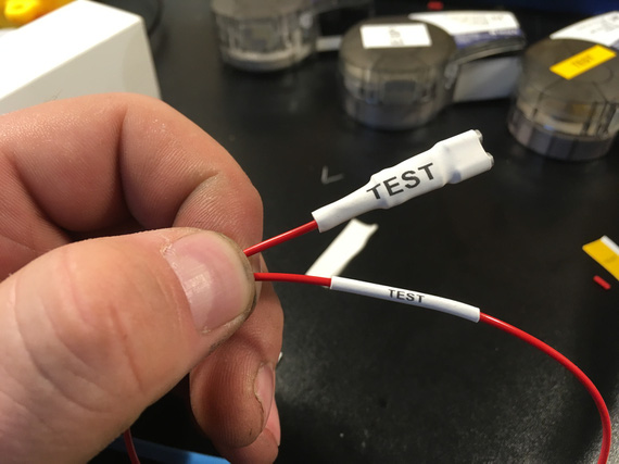
Shrunk!
Fusible Links
Every wire must be fused at the source. Well, almost every :). We don't fuse a couple wires like battery - master contactor: but this is an exception rather than the rule.
Most wires are fused on the fuse block at the main buss. But some wires are impractical or impossible to have hooked up to that. Think ammeter shunt wires as a classic example.
For those, most people use bulky, ugly, and generally eww-y inline fuses. But there's a better option! Enter fusible links.
The idea is simple: use a short length of wire 4 gauges smaller the wire to be fused. So if your wire to be fused is 20AWG, you would do:
Source -> 24AWG -> 20AWG where the 24AWG segment acts as a fuse. The idea is, in case of a short, that piece will burn first.
So, I wanted to convince myself that that will work fine for me.
Initially, me and my ham neighbor tried to use his ~30 amp power supply to do it. No joy. The best we could do is 22 amps, and (imagine that!) 24 gauge we were trying to burn held up to the abuse with no sweat at all! I could even hold it in my fingers. Yay, milspec wire!
So I decided to go rough. I do have a discarded old battery, after all. It was time to burn some wires with it.
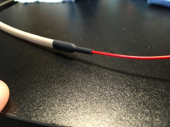
Here, the red wire is 20AWG, and the black wire is 24AWG. Using crimps for quick setup.
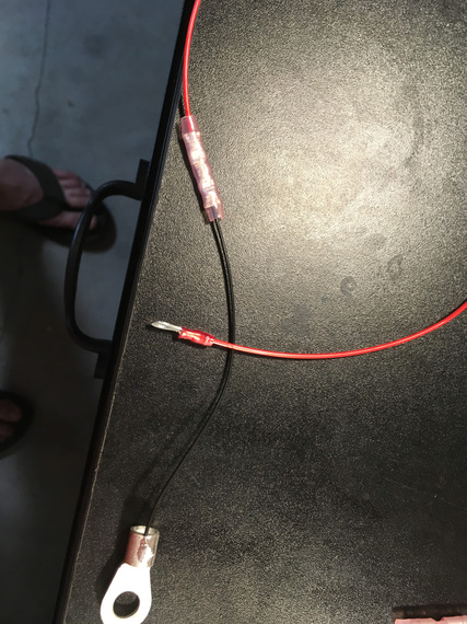
The link
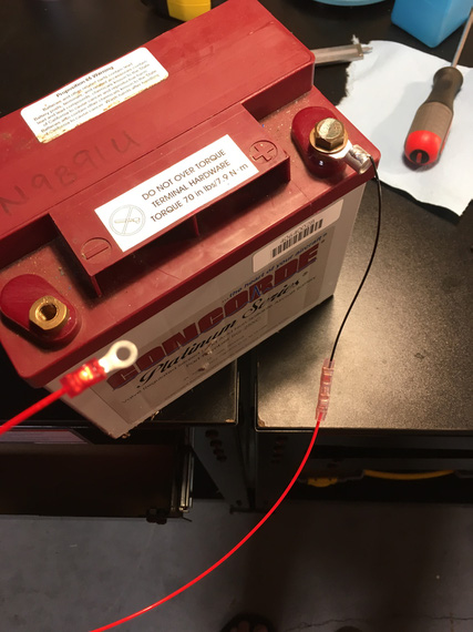
The hookup
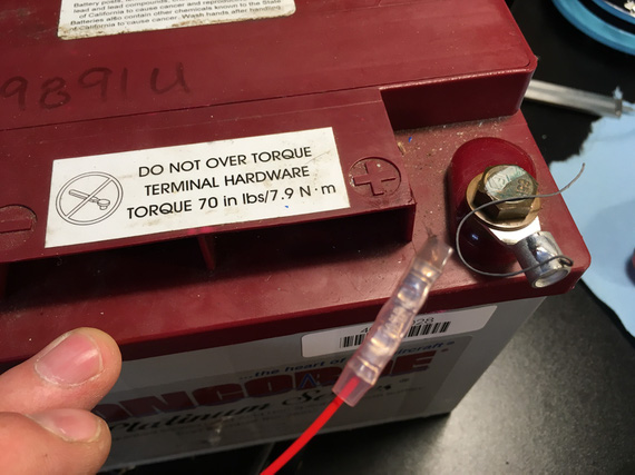
Boom!
It burnt real quick, in less than a second, and the protected (red) wire barely got hot (I was holding it - that was a part of the test). Yes, say that I am unscientific all you want - milspec wire holds up to 150C, and I can't hold up to 150C. The 20GA wire got barely warm - which means it won't cause any problems in a bundle.
It worked!
Now, it was time to set up a real one - to make sure that when the "fuse" wire burns, it doesn't damage anything.
B&C sells very nice fiberglass tubing covered in silicone for exactly this purpose.
I also soldered the fuselink in this time - I wanted to see how well will the solder splices hold to the temps.
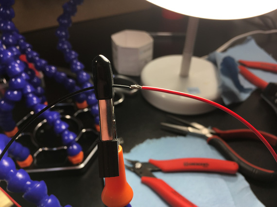
Soon to be splice
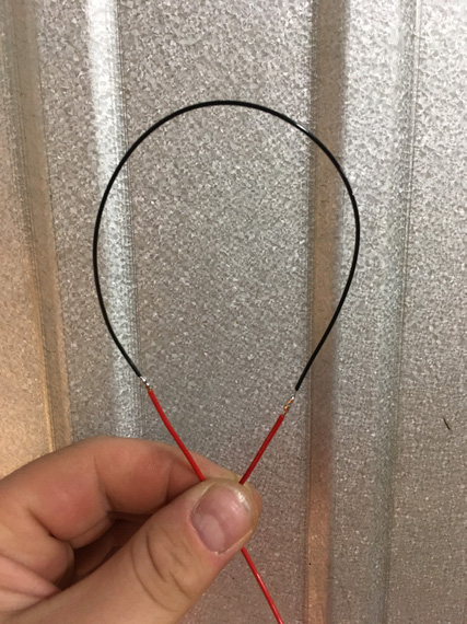
24AWG spliced into 20AWG
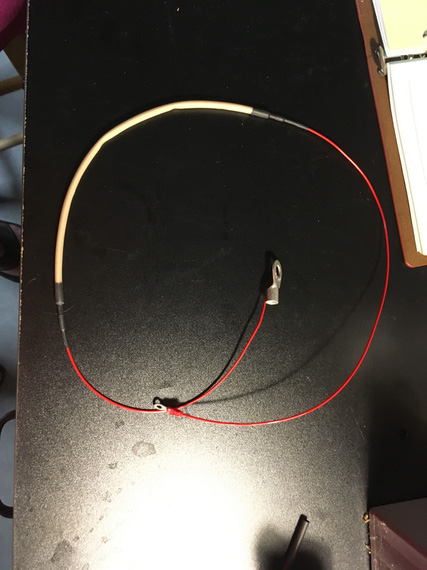
Note here: I know that in reality, the thin 24AWG wire will be the first in chain; here I'm just splicing it in the middle of 20AWG segment so that I can cover both ends. In "production" fuse links, the "source" end will be a ring terminal, and the fiberglass sleeve will go over it.
Sleeve on
With heatshrink
Ready to go!
Boom! Or not? I thought it didn't work, frankly. I didn't hear anything. I didn't smell anything. I actually took my multimeter to make sure the continuity wasn't there - it wasn't!!! Wow. The fiberglass sleeve contained the micro-explosion really well.
I took it off to inspect.
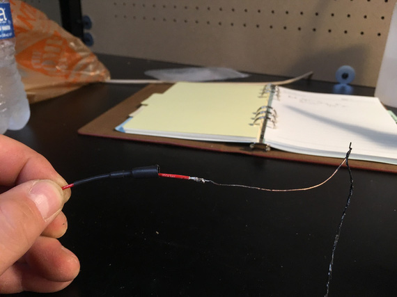
All burnt up wire
The fiberglass sleeve showed no signs of damage.
Great success!
I will need to play with different sizes of heatshrink and probably will use the glue lined strain relief kind just to support everything well, but hey - this worked very well indeed!
Load Measurements
Prior to ripping the old wiring out, I wanted to take some real life load measurements with various things turned on, so that I don't get any nasty surprises.
But this plane has no ammeter... damn. I searched around, and found this little doodad:
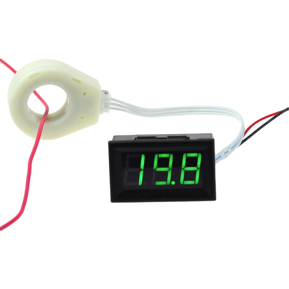
Hall Effect ammeter
Very nice. It basically measures current on the wire passing thru this big white ring using Hall effect. Very cool! No need to splice into the battery leads and install a temp shunt.
So, I rigged it up and took some numbers.
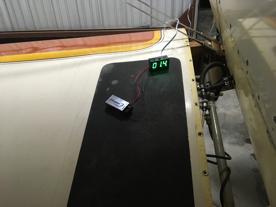
Rigged up
- Master On: 1.5 amps
- Includes: Master Solenoid, and a couple of gauges
- Fuel Pump: 0.2 amps
- "Radios" switch (turns on engine monitor, and power to radios: turning backlighting on them): 0.8 amps
- I-Com Radio, Transmit: 2.6 amps
- Intercom: 0.1 amps
- Transponder: 1.1 amps
- Smoke Oil pump: 2.2 - 2.6 amps (high on startup)
So couple interesting things here. I think the x-der number is too low, but it wasn't being interrogated, and I can't make it be interrogated without flying the plane or using a transponder tester which I don't have. Also, Master On is too high seemingly... Will need to double check later and isolate things (master solenoid, hobbs, voltmeter, voltage regulator, fuel gauge) if I care enough - I don't think I do. Also, fuel pump is too low seemingly. Need to double-check the spec.
And then, I could not turn on the Turn-Slip Indicator...
Turn-Slip Indicator
Sad, sad indicator... see, it's long. And it's wire connector is sticking out. And it's right behind the front seat's headrest, and there's just not enough room for it, and the connector.
So whomever put it in... did this:
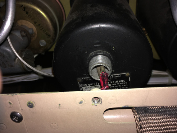
Sad, sad wiring
It's hard to see; but basically, those wires are bent "down" at a very sharp 90 degrees angle. Notice how he just used pins without the actual connector. The distance between them is tiny! I am surprised they haven't shorted over all these years. I really am.
Initially, I thought the gauge didn't turn on because that wiring was all bust up, so to test it, I decided to pull it out.
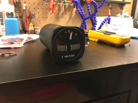
On the bench
I cut off the wires with those pins on them to hook it up to my testing battery... hmm.. but I needed some leads! Well, I was gonna make a bunch of various test leads - so this is as good a time as any! Man, I love soldering...
I long decided to make a bunch of leads with "passthru" banana plugs on one end, and something (a crocodile clamp, a battery clamp, a ring terminal) on the other. This way, I could mix and match, and plug them into my multimeter; daisy chain, and have multiples depending on what and how I needed to hook up. I had all the bits (clamps, crocodiles, banana plugs), and even got a roll of very nice super flexible silicone coated probe wire.
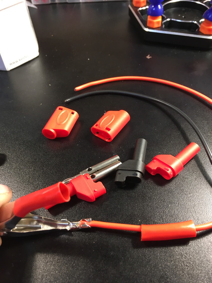
Components, and the battery clamp crimped on
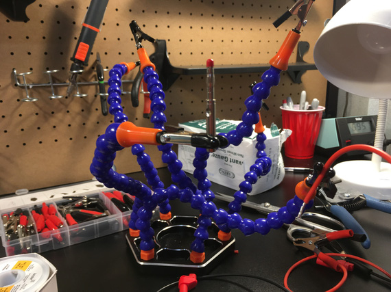
Release the Soldering Kraken!
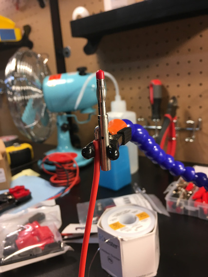
The banana plug pin
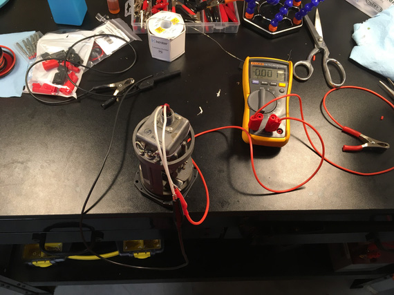
All hooked up
The gyro in the gauge didn't start. Damn.
But I had resistance between + and -. And I had voltage! Hmmm..
Second time I hooked it up, I saw a bit of a spark when I put the positive clamp to the battery, and heard something.
I spun the gyro with my finger.... it spun up!
Well, well. So that gyro "froze" in a bit... Yep, it was hard to turn over with a finger - no doubt a small motor in there had a hard time!
I probably "cleared it up" a bit when turning it over with my fingers - but that won't last long... damn.
Are we looking at the overhaul for this thing too now? Sigh.... Maybe I can find parts to do that myself, but not so sure about that.... It's not common for owners to overhaul their instruments - they're precision clockwork, after all...
Oh well.
And I will have to figure out how to solve that wiring problem with no space to hook up the right type connector. I am thinking along the lines of maybe routing a wire from inside of the gauge down thru a hole I'd drill, a grommet it it, and covering the whole business with with some sealant or something, so that the dust doesn't get in. we'll see. Need to ponder this a bit more.
Young man, was that a landing or were we shot down?
© Copyright "79FT". All rights reserved. Feel free to cite, but link back to the pages cited.
This website only shows how I did things in my various projects. These pages are for information and personal entertainment only and not to be construed as the only way, or even the perceived correct way of doing things. You are responsible for your own safety and techniques.
