[79FT]: Building Things |
 |
Wiring - Pt III
...part three: done!
| On: | Sep 07, 2020 |
| In: | [Chickenhouse Charger] Electrical Rebuild |
| Time logged: | 16.6 |
| Tags: | 6781G, MA5 Charger, electrical, panel, instruments |
... and the only bit of wiring left was the gauges at the panel.
It was not interesting in any way - mostly, lots of tying in awkward position.
A lot of stuff had to be done thru the front hole's headrest, while standing on a wing, and trying not to get "tangled" in the flying and landing wires.
Oh well.
I realized this was another mistake. Since all the gauge wires started at their transducers or sensors (amps, fuel and oil pressures, oil temp, and the like), I ran them "backwards" as one piece, and was planning to put on the corresponding D-Sub connectors in place.
What I didn't realize was how much pain it will be if I had to work in close quarters. And unfortunately, the 3-in-1 gauge - with the fattest of the connectors - required that.
What I should've done was cut the transducer and sensor's wires and made "whips" for them with connectors while on the bench. Then, I should've spliced them somewhere on the side of the airplane - yes, I'd have to do a lot of soldering, but that would've been better than what I ended up having to do...
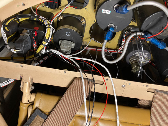
Instrument wires - and the back side of 3-in-1
You can see the DB-15 connector there - that's the 3-in-1. Sticking the wires thru the instrument hole, doing all the stripping and crimping from the panel side while sitting in the cockpit, and then tying the extra length up... maybe was possible, but seemed to me like it would be too much extra, producing ugliness and possibly rubbing on the structure nearby, so I decided to make that connector as close to the actual gauge as I could...
I tried it on the bench first, figuring out where I would put heatshrink, how much of the length is necessary for the connector, and the like.
Another interesting tidbit was that one of the connections had to feed two transducers off of the same one pin. Both wires were 22GA and I couldn't put them into the pin no matter how I tried - too much wire for one D-SUB pin's barrel. I'll show you the solution I used for that.
So, I bunched up the wires, put a round of heatshrink on, and prepped those power wires.
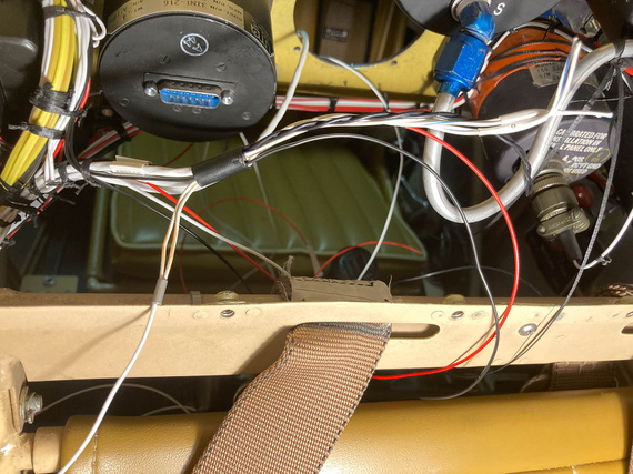
3-in-1 bundle
I bent the two power wires for transducers backwards "out" of the connector, and pigtailed a single 20ga wire to them. That looped back into the connector and hooked up to the pin.
Then, I set myself up on the wing, slouching over the front hole's combing, took my stripper, and stripped a wire... bam! 2/3ds of the strands came off...
What the..?!
I think the stripper pinched the wire when closing on it, and since I was so much out of position - practically upside down - I didn't notice...
And since I effectively just destroyed ~1/2 inch of the wire, and the wires were cut short....
I lucked out. The wire I was stripping was a standalone ground wire. Moreover, I had two more tails coming from the same source - for the other two gauges, and the unintentionally shortened tail I just made was just the right length for another gauge.
Phew. Only having to cut two knots, I re-routed the shortened wire to the other gauge, and that gauge's wire to the 3-in-1 bundle.
Tested the stripper multiple times. Yes, I think I just missed the right hole.
Making dead sure I was on this time, I tried again - phew. All worked out.
Slowly, everything got crimped.
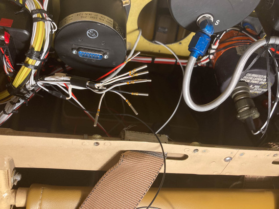
3-in-1 gauge pins
You can also see that "power loop" in the above picture.
Then, I installed the pins in the housing, and checked the 3-in-1 out. Used a plumber's gauge to pressurize pressure transducers with some appropriate amount of air and made sure the correct arrow went up on the 3-in-1, and by the right amount.
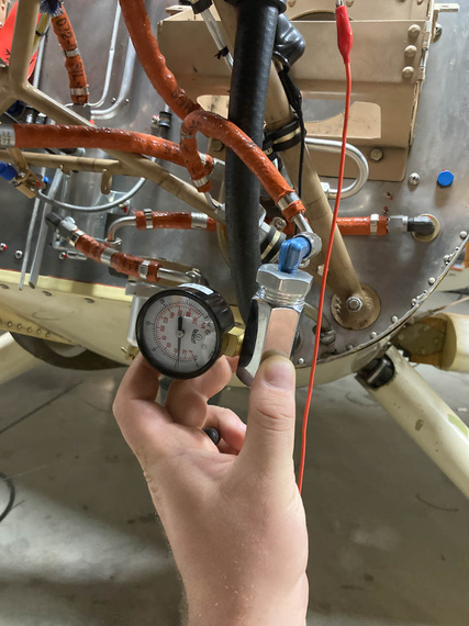
Testing pressure transducers
The other three gauges were much easier - because they were further from the 3-in-1 and tie point, for each of them I could trim and crimp the wires from the cockpit side. I had some fun times with the housing of the tach connector - a DB-9... UMA shipped me a weird sheet metal shell for it I've never seen that I think needs a special crimper to install, so I ended up replacing it with a regular cheapo plastic after spending what feels like a few hours trying to find out what the hell that shell was... Failed at that.
At any rate.
The final result? Well..
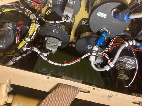
Beind the panel: done.
And with that, the re-wiring of the Charger was...
Complete!!!
"Leave five on the glide, have a nice ride, tower inside, twenty-six nine .... see ya!"
-ORD ATC
Up ↑
Wire Markings, Fuselinks, Load Measurements, and Turn-and-Slip
tested fuselinks, measured loads, removed and diagnosed turn-and-slip indicator
| On: | Jun 18, 2019 |
| In: | [Chickenhouse Charger] Electrical Rebuild |
| Time logged: | 6.5 |
| Tags: | 6781G, MA5 Charger, electrical, experiments, research, instruments, soldering |
Finally, doing some actual work on the airplane, and having fun! And I decided to start logging time.. because, why not!
Wire Marking
I like marked wires. I used to be a networking guy, and I was very meticulous about marking every single wire in my cabinets, so that I knew exactly what was plugged in where.
It took a bit of upfront time, but saved a bunch of it later on.
So naturally, I was planning to do the same on the Charger, and, more importantly, make it look professional.
Thanks to living in this day and age, that is simple. No, I'm not gonna pay someone to laser etch my wires - that's a cop out :). It's like paying someone to paint your plane.
Instead, I have researched and found a perfect label maker - Brady BMP21 (not including a link here because it will probably go dead after some time... just search for it). This thing has 3:1 heatshrink tube cartridges.
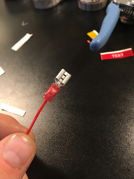
The proverbial coupon
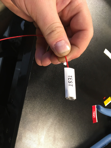
Prior to shrinking
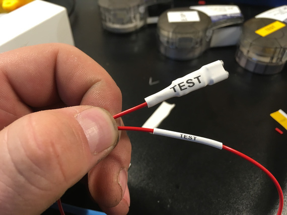
Shrunk!
Fusible Links
Every wire must be fused at the source. Well, almost every :). We don't fuse a couple wires like battery - master contactor: but this is an exception rather than the rule.
Most wires are fused on the fuse block at the main buss. But some wires are impractical or impossible to have hooked up to that. Think ammeter shunt wires as a classic example.
For those, most people use bulky, ugly, and generally eww-y inline fuses. But there's a better option! Enter fusible links.
The idea is simple: use a short length of wire 4 gauges smaller the wire to be fused. So if your wire to be fused is 20AWG, you would do:
Source -> 24AWG -> 20AWG where the 24AWG segment acts as a fuse. The idea is, in case of a short, that piece will burn first.
So, I wanted to convince myself that that will work fine for me.
Initially, me and my ham neighbor tried to use his ~30 amp power supply to do it. No joy. The best we could do is 22 amps, and (imagine that!) 24 gauge we were trying to burn held up to the abuse with no sweat at all! I could even hold it in my fingers. Yay, milspec wire!
So I decided to go rough. I do have a discarded old battery, after all. It was time to burn some wires with it.
Here, the red wire is 20AWG, and the black wire is 24AWG. Using crimps for quick setup.
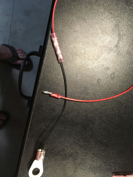
The link
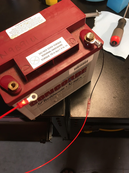
The hookup
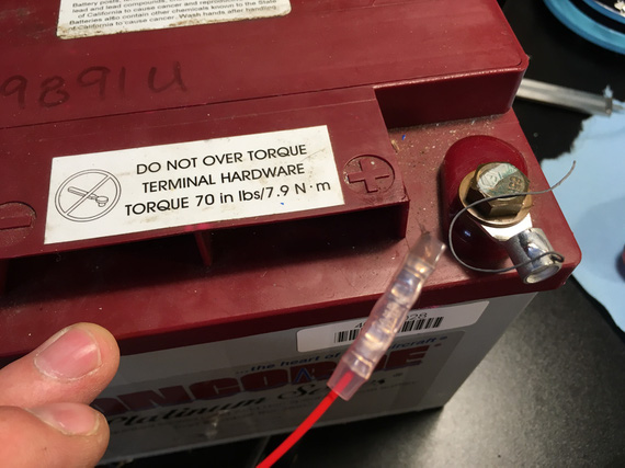
Boom!
It burnt real quick, in less than a second, and the protected (red) wire barely got hot (I was holding it - that was a part of the test). Yes, say that I am unscientific all you want - milspec wire holds up to 150C, and I can't hold up to 150C. The 20GA wire got barely warm - which means it won't cause any problems in a bundle.
It worked!
Now, it was time to set up a real one - to make sure that when the "fuse" wire burns, it doesn't damage anything.
B&C sells very nice fiberglass tubing covered in silicone for exactly this purpose.
I also soldered the fuselink in this time - I wanted to see how well will the solder splices hold to the temps.
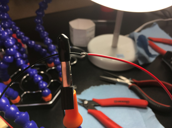
Soon to be splice
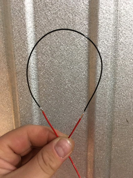
24AWG spliced into 20AWG
Note here: I know that in reality, the thin 24AWG wire will be the first in chain; here I'm just splicing it in the middle of 20AWG segment so that I can cover both ends. In "production" fuse links, the "source" end will be a ring terminal, and the fiberglass sleeve will go over it.
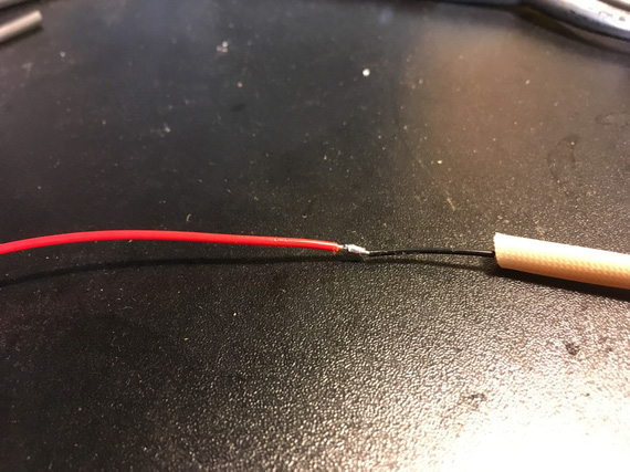
Sleeve on
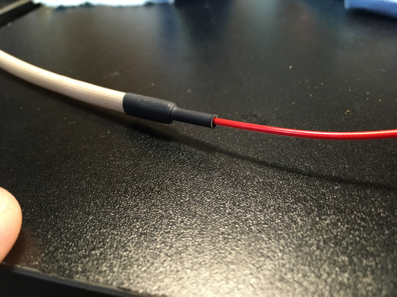
With heatshrink
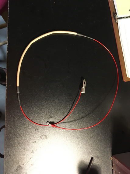
Ready to go!
Boom! Or not? I thought it didn't work, frankly. I didn't hear anything. I didn't smell anything. I actually took my multimeter to make sure the continuity wasn't there - it wasn't!!! Wow. The fiberglass sleeve contained the micro-explosion really well.
I took it off to inspect.
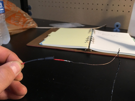
All burnt up wire
The fiberglass sleeve showed no signs of damage.
Great success!
I will need to play with different sizes of heatshrink and probably will use the glue lined strain relief kind just to support everything well, but hey - this worked very well indeed!
Load Measurements
Prior to ripping the old wiring out, I wanted to take some real life load measurements with various things turned on, so that I don't get any nasty surprises.
But this plane has no ammeter... damn. I searched around, and found this little doodad:
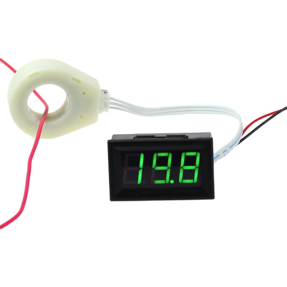
Hall Effect ammeter
Very nice. It basically measures current on the wire passing thru this big white ring using Hall effect. Very cool! No need to splice into the battery leads and install a temp shunt.
So, I rigged it up and took some numbers.
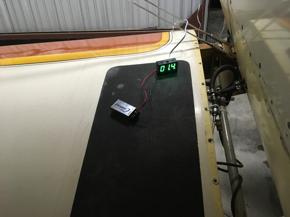
Rigged up
- Master On: 1.5 amps
- Includes: Master Solenoid, and a couple of gauges
- Fuel Pump: 0.2 amps
- "Radios" switch (turns on engine monitor, and power to radios: turning backlighting on them): 0.8 amps
- I-Com Radio, Transmit: 2.6 amps
- Intercom: 0.1 amps
- Transponder: 1.1 amps
- Smoke Oil pump: 2.2 - 2.6 amps (high on startup)
So couple interesting things here. I think the x-der number is too low, but it wasn't being interrogated, and I can't make it be interrogated without flying the plane or using a transponder tester which I don't have. Also, Master On is too high seemingly... Will need to double check later and isolate things (master solenoid, hobbs, voltmeter, voltage regulator, fuel gauge) if I care enough - I don't think I do. Also, fuel pump is too low seemingly. Need to double-check the spec.
And then, I could not turn on the Turn-Slip Indicator...
Turn-Slip Indicator
Sad, sad indicator... see, it's long. And it's wire connector is sticking out. And it's right behind the front seat's headrest, and there's just not enough room for it, and the connector.
So whomever put it in... did this:
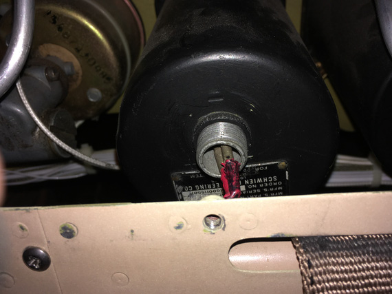
Sad, sad wiring
It's hard to see; but basically, those wires are bent "down" at a very sharp 90 degrees angle. Notice how he just used pins without the actual connector. The distance between them is tiny! I am surprised they haven't shorted over all these years. I really am.
Initially, I thought the gauge didn't turn on because that wiring was all bust up, so to test it, I decided to pull it out.
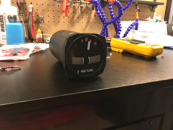
On the bench
I cut off the wires with those pins on them to hook it up to my testing battery... hmm.. but I needed some leads! Well, I was gonna make a bunch of various test leads - so this is as good a time as any! Man, I love soldering...
I long decided to make a bunch of leads with "passthru" banana plugs on one end, and something (a crocodile clamp, a battery clamp, a ring terminal) on the other. This way, I could mix and match, and plug them into my multimeter; daisy chain, and have multiples depending on what and how I needed to hook up. I had all the bits (clamps, crocodiles, banana plugs), and even got a roll of very nice super flexible silicone coated probe wire.
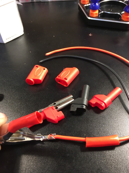
Components, and the battery clamp crimped on
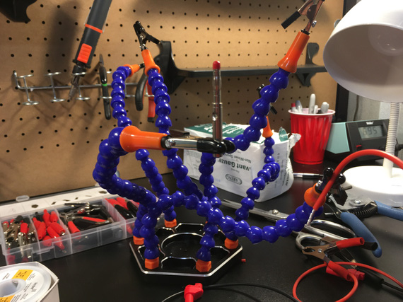
Release the Soldering Kraken!
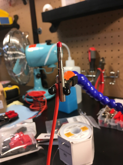
The banana plug pin
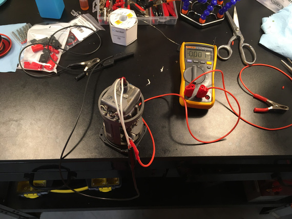
All hooked up
The gyro in the gauge didn't start. Damn.
But I had resistance between + and -. And I had voltage! Hmmm..
Second time I hooked it up, I saw a bit of a spark when I put the positive clamp to the battery, and heard something.
I spun the gyro with my finger.... it spun up!
Well, well. So that gyro "froze" in a bit... Yep, it was hard to turn over with a finger - no doubt a small motor in there had a hard time!
I probably "cleared it up" a bit when turning it over with my fingers - but that won't last long... damn.
Are we looking at the overhaul for this thing too now? Sigh.... Maybe I can find parts to do that myself, but not so sure about that.... It's not common for owners to overhaul their instruments - they're precision clockwork, after all...
Oh well.
And I will have to figure out how to solve that wiring problem with no space to hook up the right type connector. I am thinking along the lines of maybe routing a wire from inside of the gauge down thru a hole I'd drill, a grommet it it, and covering the whole business with with some sealant or something, so that the dust doesn't get in. we'll see. Need to ponder this a bit more.
Young man, was that a landing or were we shot down?
© Copyright "79FT". All rights reserved. Feel free to cite, but link back to the pages cited.
This website only shows how I did things in my various projects. These pages are for information and personal entertainment only and not to be construed as the only way, or even the perceived correct way of doing things. You are responsible for your own safety and techniques.
