[79FT]: Building Things |
 |
Motor Start
...:)
| On: | Oct 15, 2020 |
| In: | [Chickenhouse Charger] Electrical Rebuild |
| Time logged: | 23.0 |
| Tags: | 6781G, MA5 Charger, FWF, electrical, engine, exhaust, alternator, fabrication |
And so, we're onto the race to the first motor run. I am writing this about a month later - according to the log, the motor was started up September 19, 2020.
But first...
Upfront
Finish mounting the starter was no problem: clean up the threads, clean up the studs, torque, done. Then, the alternator.
Belt tensioning... too annoying by hand, but it took me a while to stop trying and become sensible.
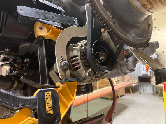
Belt Tensioning
You gotta safety two bolts over there, and I decided to make it nice: for the bottom (pivot) bolt, drilled a tiny hole in the bracket lower than where the alternator would be, and for the top bolt attaching the bracket to the motor... hmmm...
Somewhere on VansAirforce someone used a cherry rivet as a "hookup" point for the safety wire. I thought to one-up that, and use a short #8 screw - drilling it's head.
Frankly, I didn't think it'd work out.
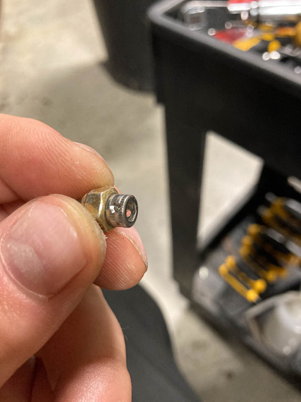
Drilled cap head
...but as you can see, it did.
So then, to the hole in the bracket. I needed a #8-32 tap.
Side, fun, story: quite a while ago I ended up bidding in a machine shop liquidation auction. Got quite a few nice things, including a very heavy duty bandsaw - and, accidentally, a massive cabinet full of tooling. Anything you could imagine: inserts, drills, taps, slitting saws, you name it. In all shapes and sizes. When we moved the cabinet, we emptied it into about 10 boxes, so ... I did have a #8-32 tap. In fact, probably about 20 of them. Question was, which one of the boxes were they in.
... apparently, in the one on the top. Hmm. This kind of luck is unusual.
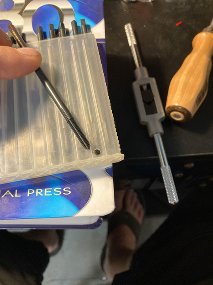
Tap
Look at it carefully. Does it look like a regular tap we are all used to?
Didn't to me either.
So to researching we went.
Aha! "Threadforming" tap. AKA "Cold Rolling". So that's how they're done. Rolled threads are formed into the metal rather than cut; giving them superior strength. Basically, the tap shapes the metal, displacing it in the valleys and raising peaks.
Company that made these taps was advertising them for CNC milling. Well, what's a human if not a bio-CNC machine?!
Okay, problem number 2. I was pretty sure normal tap and drill chart values for hole diameters won't work; making too small a hole. Hmm...
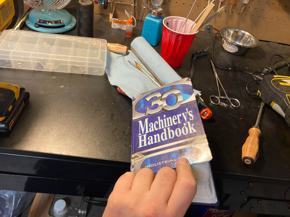
The Bible
Aha! "Ideal Theoretical Hole", and closest drill available charts are just what's needed.
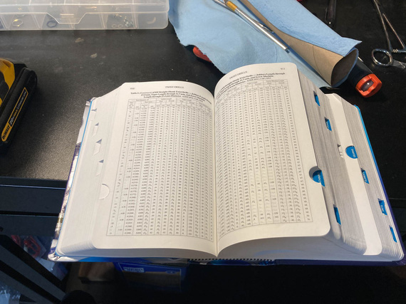
The Word
And with that, the affair was a non-event.
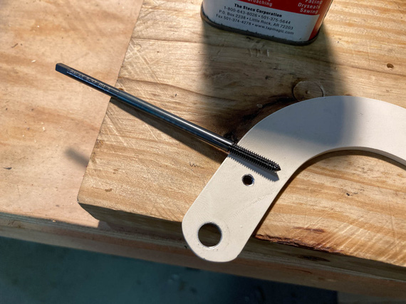
The Hole
Actually safetying was annoying - I had to try twice, because I had to use a hand-twister and you had to get the length just right.
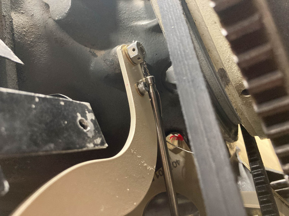
Hand Twister
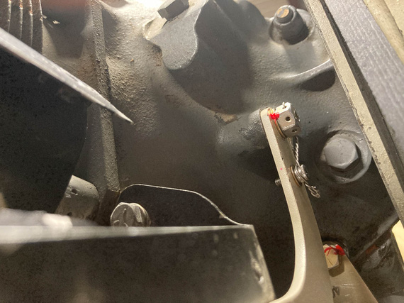
Safetied!
Airbox
That thing needed to be put back on, and carb final torqued with a new gasket. Cleaned it all up inside as much as I could, and had to cut a couple of special gaskets that I can't for the love of me figure out where to get (carb's base is different size from the top - and this is an "airframe" problem - read, "no standard part from Marvel or Lycoming I could find reasonably"). No problem. Used the same material Lycoming used for their gaskets, ordered from McMaster, and made me a couple.
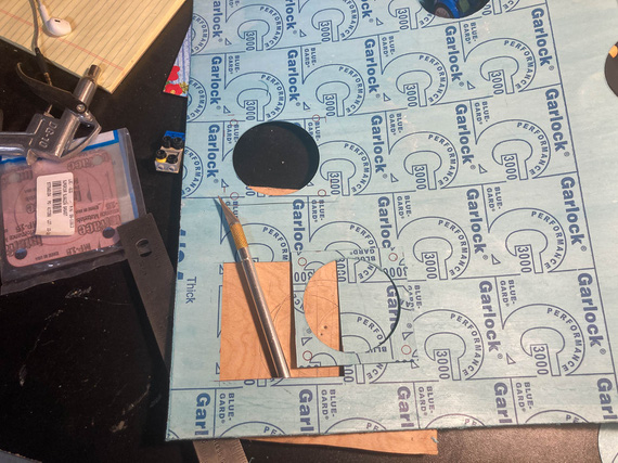
Cutting gaskets
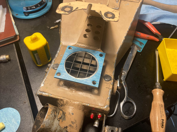
Where they go
Perceptive will see the "airflow straightener". Glenn had it on when he put on the Rotec TBI, and in the times of my research of TBIs, I have discovered that some folks claimed they helped on carbureted motors as well. Well, it definitely won't hurt - aside from my having to do two gaskets instead of one. No biggie.
Carb
One interesting thing that happened. I had to drain the carb bowl of all the preservative oil, and flush it, so I took off the plug, drained it, and started putting it back in. Plug's an NPT thread with torque listed by Lycoming in SSP-1776 at 144 inch pounds.
Hmmm.. I noticed it was going in way deeper than it was in before, and way "harder" than when I took it out.
Hmmm.. Well, it's Lycoming, they know what the hell they're talking about. So in it went, at 144 inch/lbs.
But this bugged me. I think some other day I pulled out the Marvel's manual. 25-30 inch/lbs?! WHAT?!
Back to Lycoming. 144. Marvel (the makers of the carb)? 25-30. Damn it. Forums? Nothing interesting.
I finally figured it out. In SSP-1776, in the table for special torques, Lycoming lists the plug to have 3/4 pipe threads. Mine were 1/8 NPT. Lycoming's torque for those is 40-44 inch/lbs. Still higher than Marvel, but much closer now.
So, I undid the plug, that cut a bit of the tapered thread "deeper", of course. And put it back in, with the right torque this time.
Other Stuff
And then, minor stuff here and there. Cleaned and prepped spark plugs. Put the exhaust back on. Tightened things that had to be tightened. Charged batteries. Tied up everything hanging loose. Gave the plane a good look all over.
We were ready for the final day. There were a number of things I needed two sets of hands for, and I had just the man lined up.
Day X - or, September 19, to be Precise.
My buddy Mr. N. agreed to help, and be my observer and fireman (just in case). Mr. M. was extremely inquisitive about how we're gonna be putting out a burning airplane, and I had to explain a number of times that the goal of an exercise of starting a motor that's been idle for a year is not to have it go ablaze, and having a fire watch nearby is a part of prudence, not expectations. He seemed to have been disappointed. I would be too, if I was 5.
So, on a nice Saturday, we went to the airport.
First, drained all the pickling oil. Took off the prop (because we'd have to spin the motor to pressurize the oil lines). Put the fuel pump back on. Tightened all new fuel lines, and leak checked them. Mr. M. used my fancy "button with alligator clips" to turn it on. Put new oil in, primed the oil cooler and pump (and this is fun in this airplane, because there's no oil filler neck on the motor). Checked control cable travel, and final cotter pinned them. Checked brakes again (though we bled them when I finished fixing them up).
Then, came the pressurization, and purging of oil lines, time. Mr. M insisted that he wants to "press the button" - which would put +12V onto the starter contactor; bypassing my normal starting circuit (latter would make the left mag hot, and I didn't want that).
I told him to press the button and hold it and not let go till I told him to.
Now, starters with a motor with removed spark plugs are fast, loud, and annoyingly sounding. Mr. M. pressed the button. Jumped a bit. Grimaced a bit. He clearly didn't expect it. I didn't see it, Nick told me afterwards - I was watching the oil line. I yelled "Stop" when I saw the oil come out, and looked at Mr. M - who, at that point, was shaking and at the point of breaking down in tears. But! He didn't let go of the damn button. Man.
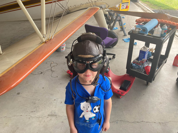
Mr. M
And that was that. Plugs went in, and we were ready, but broke for lunch, first. Mr M deserved his hot dog.
... back from lunch. Plane out. Wheels chocked. Brakes tested. Fire watch ready and instructed.
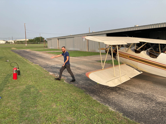
Final prep
... damn, that old Concord battery removed from the Cheetah years ago is weak and barely pulling thru.
... second try: no primer, so I have to pump the throttle a bit.
... she's alive!!!!!
I let the temps go up just a bit, and called N. He confirmed everything seemed to have been fine. We shut down, and went over every fluid fitting. All good.
Started her back up - I wanted to warm the oil to a reasonable temp and let her circulate for a bit, maybe 30 minutes - to get the juice flowing again.
On the second run, I revved her harder, and smelled something. Smelled like... burnt wiring? N. went around the engine, all wires, and everything he could see or think was close to being to a hot surface, or an electrical doodad. No signs of trouble.
We decided to proceed.
She ran just fine. I think we ran for about a total of 30 minutes. Shut her down, dragged her in. Went over the wires again - all of them. Nothing, all clean. There were no bad indications on any of the electrical instrumentation, either. So at that time, we left that as a mystery to be solved.
... and with that, we went home. We were tired.
Flying is better than walking. Walking is better than running. Running is better than crawling. All of these however, are better than extraction by a Med-Evac helicopter, even if this is technically a form of flying.
Up ↑
Wiring - Pt III
...part three: done!
| On: | Sep 07, 2020 |
| In: | [Chickenhouse Charger] Electrical Rebuild |
| Time logged: | 16.6 |
| Tags: | 6781G, MA5 Charger, electrical, panel, instruments |
... and the only bit of wiring left was the gauges at the panel.
It was not interesting in any way - mostly, lots of tying in awkward position.
A lot of stuff had to be done thru the front hole's headrest, while standing on a wing, and trying not to get "tangled" in the flying and landing wires.
Oh well.
I realized this was another mistake. Since all the gauge wires started at their transducers or sensors (amps, fuel and oil pressures, oil temp, and the like), I ran them "backwards" as one piece, and was planning to put on the corresponding D-Sub connectors in place.
What I didn't realize was how much pain it will be if I had to work in close quarters. And unfortunately, the 3-in-1 gauge - with the fattest of the connectors - required that.
What I should've done was cut the transducer and sensor's wires and made "whips" for them with connectors while on the bench. Then, I should've spliced them somewhere on the side of the airplane - yes, I'd have to do a lot of soldering, but that would've been better than what I ended up having to do...
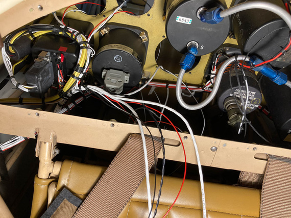
Instrument wires - and the back side of 3-in-1
You can see the DB-15 connector there - that's the 3-in-1. Sticking the wires thru the instrument hole, doing all the stripping and crimping from the panel side while sitting in the cockpit, and then tying the extra length up... maybe was possible, but seemed to me like it would be too much extra, producing ugliness and possibly rubbing on the structure nearby, so I decided to make that connector as close to the actual gauge as I could...
I tried it on the bench first, figuring out where I would put heatshrink, how much of the length is necessary for the connector, and the like.
Another interesting tidbit was that one of the connections had to feed two transducers off of the same one pin. Both wires were 22GA and I couldn't put them into the pin no matter how I tried - too much wire for one D-SUB pin's barrel. I'll show you the solution I used for that.
So, I bunched up the wires, put a round of heatshrink on, and prepped those power wires.
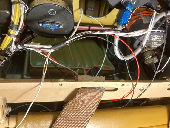
3-in-1 bundle
I bent the two power wires for transducers backwards "out" of the connector, and pigtailed a single 20ga wire to them. That looped back into the connector and hooked up to the pin.
Then, I set myself up on the wing, slouching over the front hole's combing, took my stripper, and stripped a wire... bam! 2/3ds of the strands came off...
What the..?!
I think the stripper pinched the wire when closing on it, and since I was so much out of position - practically upside down - I didn't notice...
And since I effectively just destroyed ~1/2 inch of the wire, and the wires were cut short....
I lucked out. The wire I was stripping was a standalone ground wire. Moreover, I had two more tails coming from the same source - for the other two gauges, and the unintentionally shortened tail I just made was just the right length for another gauge.
Phew. Only having to cut two knots, I re-routed the shortened wire to the other gauge, and that gauge's wire to the 3-in-1 bundle.
Tested the stripper multiple times. Yes, I think I just missed the right hole.
Making dead sure I was on this time, I tried again - phew. All worked out.
Slowly, everything got crimped.
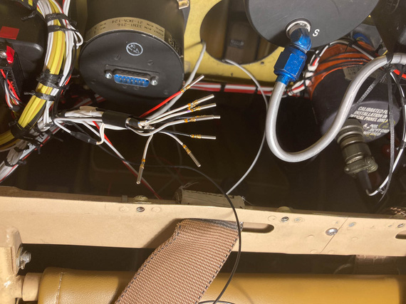
3-in-1 gauge pins
You can also see that "power loop" in the above picture.
Then, I installed the pins in the housing, and checked the 3-in-1 out. Used a plumber's gauge to pressurize pressure transducers with some appropriate amount of air and made sure the correct arrow went up on the 3-in-1, and by the right amount.
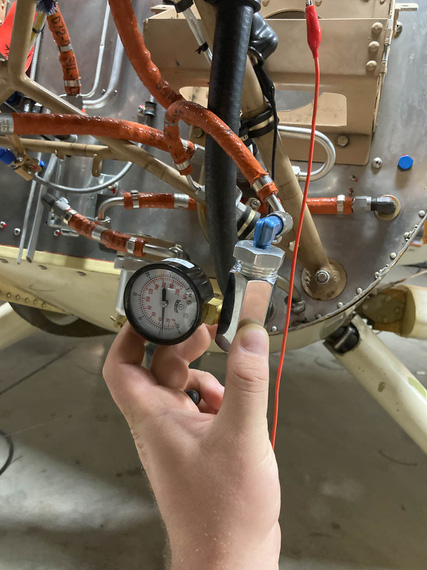
Testing pressure transducers
The other three gauges were much easier - because they were further from the 3-in-1 and tie point, for each of them I could trim and crimp the wires from the cockpit side. I had some fun times with the housing of the tach connector - a DB-9... UMA shipped me a weird sheet metal shell for it I've never seen that I think needs a special crimper to install, so I ended up replacing it with a regular cheapo plastic after spending what feels like a few hours trying to find out what the hell that shell was... Failed at that.
At any rate.
The final result? Well..
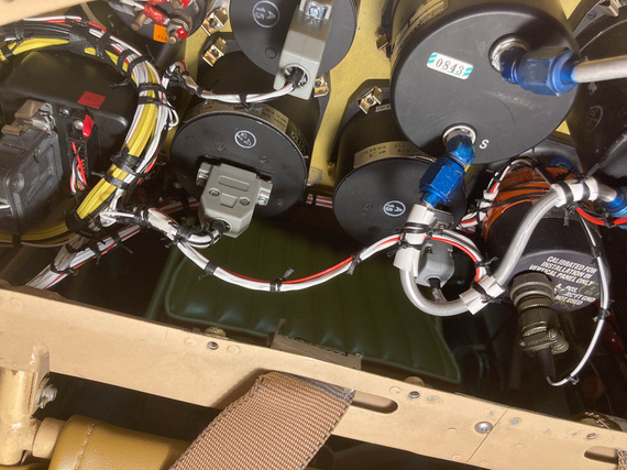
Beind the panel: done.
And with that, the re-wiring of the Charger was...
Complete!!!
"Leave five on the glide, have a nice ride, tower inside, twenty-six nine .... see ya!"
-ORD ATC
Up ↑
Wiring - Pt II
...part two
| On: | Sep 06, 2020 |
| In: | [Chickenhouse Charger] Electrical Rebuild |
| Time logged: | 18.21 |
| Tags: | 6781G, MA5 Charger, electrical, soldering, fwf, magnetoes, p-lead |
Well, we're continuing happily with wiring over here :).
Wingtips
SkyBeacon and SkySensor were to replace the existing nav lights. Yes, I know, SkySensor is probably a gimmick. But what the hell.
Remo ran nav light wires in a -4 tubing along the front wing spar, using it as kind of a "conduit", exiting the wires around the wingtip, and just soldering them to the nav lights he used. Wires were ~3 ft too long, which is a fine "service whip", but they were just laying on top of the inside of the fabric of the wingtip. There are no access holes on the wingtip, so no way to get in to tie them up.
Oh well. We work with what we have.
I was going to shorten the wires, and because the lights are on the top wing, I didn't want to solder them - I'd be doing it off of a ladder, very near if not on the wing's fabric... lots of things to go wrong.
The other thing I didn't want to happen was to have the connection points between the light's wire pigtails and wires in the wings to "rattle around" the wingtip (with no way of tying them down).
So I had this brilliant idea. The pic is post-realizing the idea was a mistake, with HST cut off....

SkySensor, and cut off HST
The lights had this plastic tube coming out thru which the wires were routed. I would shorten the pigtails as much as I could (like on the picture basically), hook'em up to the wing wires with barrel crimps, and put a long piece of my favorite glue-lined SCL tubing over them - with it glueing itself to the plastic tube and to the wires, creating one rigid "tube" coming off of the light...
Boy was that a mistake.
The tubing glued itself to the wires alright - but not to the plastic tube. So the whole thing created a rattly "lever" that would pull the wires thru that tube when vibrated - loading the soldered joints on the PCB of the SkySensor.
Not Good At All.
So that idea had to go to trash, and I had to cut the heatshrink off, carefully, with all the glue, without damaging the wires...
And ended up having to do exactly what I was trying to avoid - having rattling connections between the wing wires and the light, and to solder them. Why solder? Well, because the barrel crimps are heavy, relatively speaking, and I didn't want those heavy "bumps" bouncing around inside the wingtip, even with HST around them.
So, solder.
From the ladder, on top of the wing, covered in fabric.
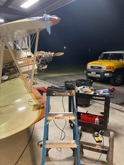
Soldering setup
You can see the heating station on top of the ladder, and the light ready on some layer of paper towels on top of the wings.
As usual, I used the Nuckolls Splice.
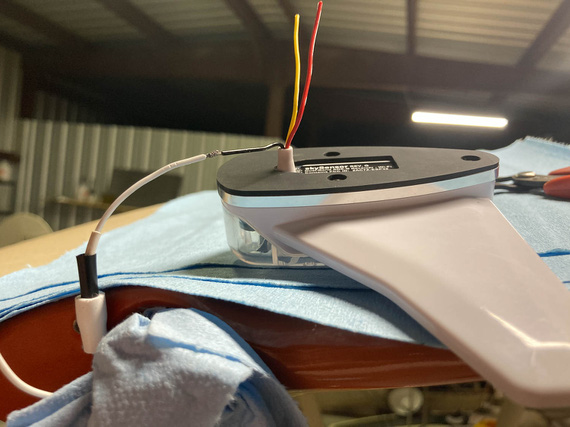
Prepped for soldering
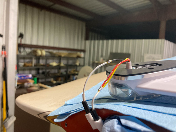
All soldered
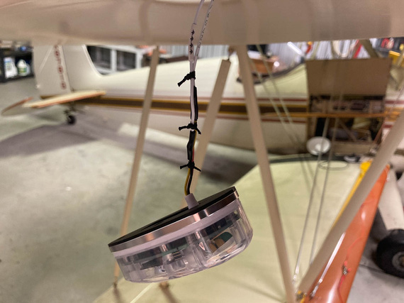
HST, and ties
The other side got the same treatment, and...
Let there be light!
The other fun part? On the left side, Remo had standard 6-32 tapped holes in whatever the backing of the light socket for the navlight was made out of. I couldn't really see - maybe a nutplate, maybe just tapped sheet metal.
But on the right side, he used sheet metal screws. Which, of course, I didn't know about till I started putting the lights on - because I took apart the left side when checking if SkyBeacon will fit, and assumed the other side would be exactly the same. As usual, rookie mistake. By now, I should know to check everything.
Well, that was a minor delay. Spruce / AN standard doesn't have screws with the right size head (#6 AN screws have heads too large to fit on the SkyBeacon and SkySensor), so McMaster-Carr had to be resorted to to get the right size and length sheet metal screws.
P-Leads
The Charger has the Bendix mags, and the P-lead connectors on those are not ring-terminated; instead, using a "screw in" type deal.

Bendix type p-lead connector - old wire
Basically, the shielded wire goes thru the outer bushing. The ferrule is a "T"-shaped sleeve, and shield get spread out over the "shank" of the T. It's squished between the outer bushing's base and the "flat" of the T of the inner ferrule.
The center wire goes thru an insulating spacer (that brown piece), and thru a washer on the other end - with a "button" of solder built on top of the washer to create a contact point.
The whole contraption gets screwed into the mag's receiving hole with the nut - ferrule rests against the mag's casing, pushing on the insulator and the solder button to contact the contact point inside the mag, while the nut pushes on the outer bushing and clamps the shield between it's base and the inner ferrule.
Now, that works with something like 16GA wire, and it's too big with my small 20GA P-leads. Also, notice how beat up the shield on that setup is? That's the old P-lead.
Folks make adapters for these to go to ring terminals, but they run something like $100 per, which is just silly, so I was determined to make this work.
Here was my idea, and what it looked like on the right mag. Note two P-lead wires - one of them goes to the front cockpit's tach.
We pigtail the shield.
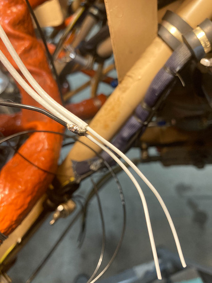
Shield pigtail
That gets heatshrunk - and the diameter is just right to go thru the ID of the ferrule.
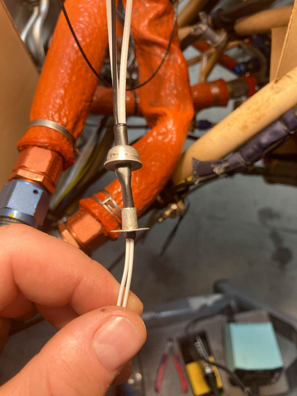
First layer of heatshrink, thru the ferrule
Then, the second layer of heatshrink goes over the ferrule, "sandwiching" it between the two layers of HST.
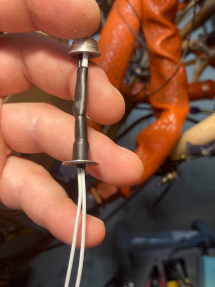
Second layer of heatshrink
And with that, the bushing would slide over the outer heatshrink... but wait. Not so fast! The hole in the bushing's too small, maybe just by .010 too small, to fit over that layer.
Damn.
After playing with various heatshrinks for the outer layer, and trying to slide the bushing on while the HST was hot, I gave up, and...
... just enlarged the hole in the bushing. Yes, I know. The bushing seems to be CAD plated, and I surely took it off (the bushing was magnetic). We'll see how it fares - if I see rust, I can always buy the adapters for silly prices.
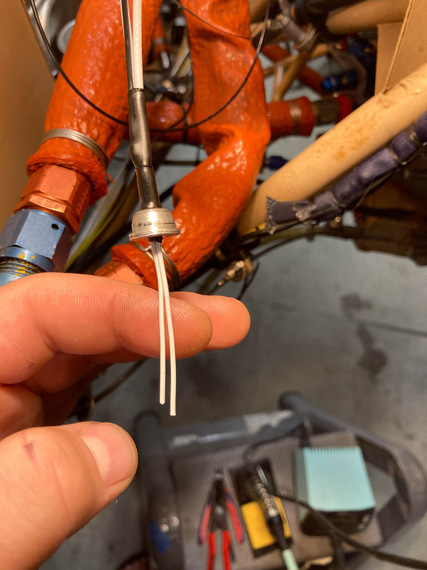
Bushing over ferrule covered in HST
And the rest is easy - fish the center wire (well, wires in this case, but same deal) thru the insulator, washer, and put the solder button on. Except that this is FWF ... hmm...
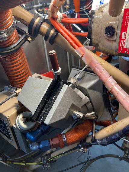
Soldering setup
Another exterme soldering setup? Well, not as much as the wingtips were...
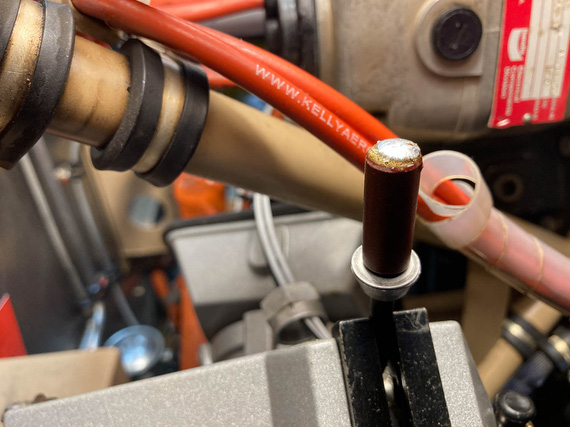
Solder button on and cooling off
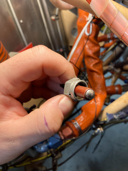
All done
And, screw the whole deal in.
P-lead attached to the mag
FWF, finishing up
And then, the rest of FWF. The only other interesting tidbit was my thinking about the Starter Warning light wire. It's one that goes off of the "I" terminal of the starter contactor - which goes "hot" when the starter contactor closes - to indicate "starter engaged" with a light. The whole shebang is probably superficial, but I convinced myself that I wanted it if for nothing else than to maintain "symmetry" of lights on my panel.
Silly.
Anyway, that wire needed a fuse - though it's an intermittent wire, and I'll admit to thinking about maybe not having a fuse on it, decided to do it, because it wouldn't harm a thing.
Used a 1A "legged" type PCB mount fuse there.
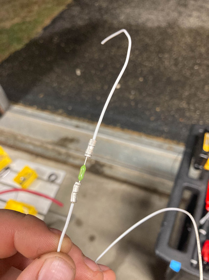
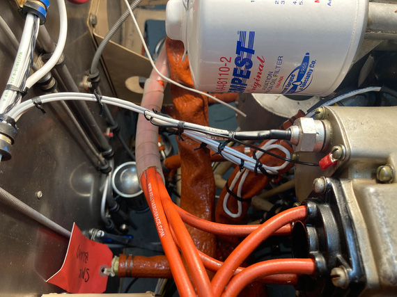
Inline fuse for the "starter warn" wire
The rest of FWF was nothing interesting to write about... Contactors, fuel pump, monitor harness, and the like. Tons of knots.
Got rid of all the remaining zipties and plastic "coils" around the ignition wires, too.
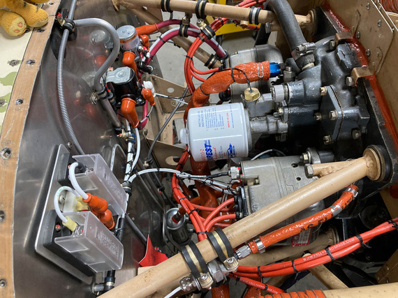
FWF - right side
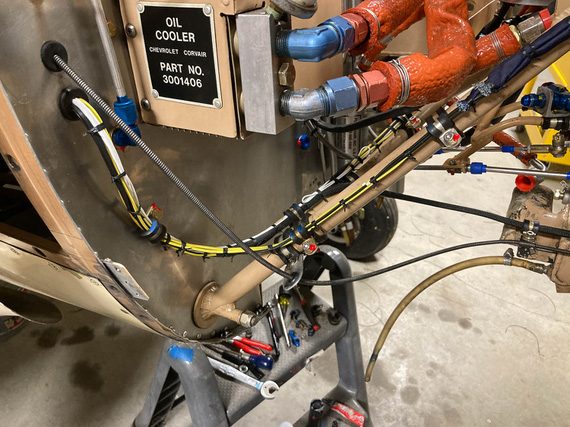
Right side - engine monitor harness
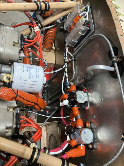
FWF - left side
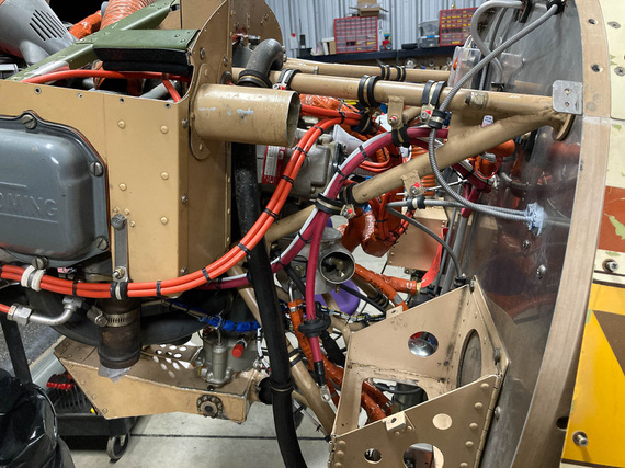
Left side - ignition harness, and battery wires
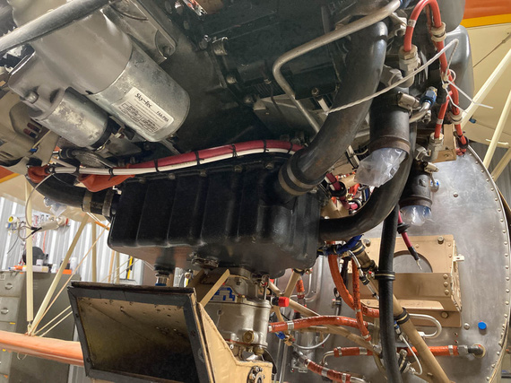
Underside - starter, and alternator wires
Flying is the second greatest thrill known to man…. Landing is the first!
Up ↑
Wiring!
...part one
| On: | Jul 26, 2020 |
| In: | [Chickenhouse Charger] Electrical Rebuild |
| Time logged: | 95.6 |
| Tags: | 6781G, MA5 Charger, electrical, soldering, fwf, panel |
Well, damn. With almost a year (no, more than a year!) of my being a caretaker of the Chickenhouse Charger, I finally was about to actually begin what I have started - which was, putting in my wires.
I decided to start at the switches, and run from the panel forward. Some wires will terminate at the fuse blocks (power feeds), and some will go forward - to the front panel, voltage regulator, and firewall forward.
Then, I was planning to run a few wires backwards - the ones that were pre-terminated on my transducers (fuel, oil pressures, oil temp, and mag pickup for the tach).
Immediately, I will admit: that was a mistake. While the harness turned out alright, it could've been much neater - if I ran in one direction. I could've made sure the whole thing is wire to wire and perfectly clean. So I should've run front to back, because my pre-terminated wires all "started" upfront.
In other words, prop to tail. Well sigh. Next time. On the other hand, this approach would've made terminating switches at the panel a nightmare. That was, initially, the reason why I wanted to start at the panel - so that I'd pre-attach wires to switches, tie them up, and then trim them at the other end.
At any rate.... Shall we?
Prep
Couple things to knock off before I started wiring was to complete the back panel. One thing that was left was the compass correction card bracket. No problem, drilled and tapped a couple holes for #2 brass screws.
Here's Mr. M. installing it:
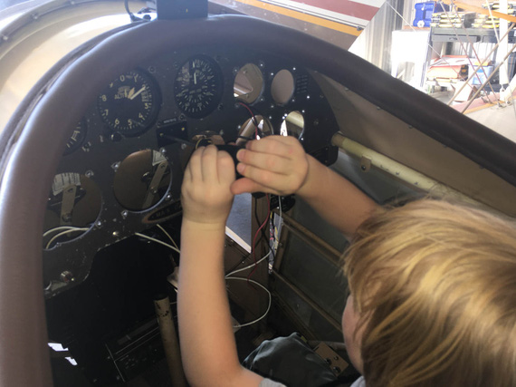
Compass Correction Card Bracket
The other one was the inertia switch for the smoke system. Glenn had it in for "safety": in the event of a shock (crash?) the switch breaks the circuit. I am.. not sure why he would have it, but he had it.
I considered not putting it back in, but what the hell.
Here's the switch:

Shock switch
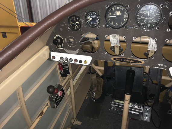
The problem was, it sat tightly between other switches in the panel. With old layout, that barely worked; but with the new layout, and Honeywell double throw switches, the connector plug was getting in the way. So I had to resort to some vandalism. :)

Removed the connector and the shroud
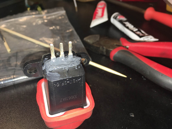
Epoxy around the tabs
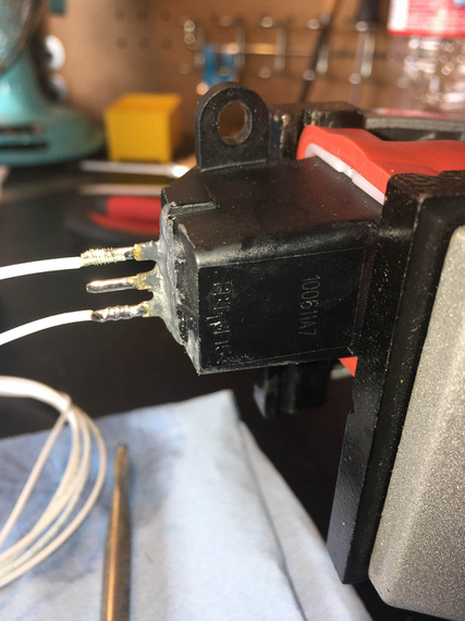
Solder!
And the switch fit nicely. Here it is, tucked between the switches. You can see how that connector would've interfered.

Shock Switch between other switches
The final prep thing was enlarging two holes for ground points to #10 and cleaning the back side up to expose nice shiny aluminum.
Panel
Now ready, I decided to install the switches first, and then wire them from the back. I needed a couple short jumpers though to connect them, and to set up some wires to be the exact length. That'd be impossible with switches installed in the panel (too little access), so I set up an old placard plate, installed switches into it, and worked on those jumpers and terminations on the bench before moving them to the airplane.

Switches on the bench mockup
Here's a couple more pictures of soldering and terminating fun pics:

Warning light socket
(that flux got cleaned off, of course).
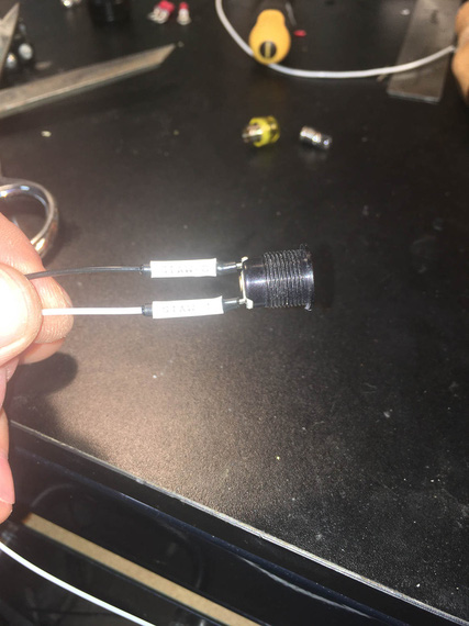
Tagged and shrunk
The heatshrink I'm using for these and in fact all my soldered joints is special strain relief kind with glue in it, specifically, Raychem SCL. It's 3:1 and it is very rigid - almost completely rigid. It definitely adds more support than the typical PIDG crimp used everywhere.
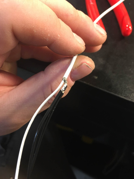
Pigtailing shielded p-lead
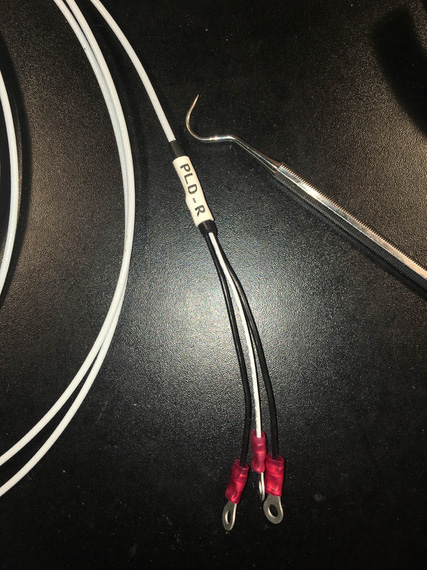
Finished with rings, HST, and tag
And then, switches went in, got tightened and straightened up, and I started running the wires.

Somewhere in the middle of running the wires
I think it happened when I was yet again sitting in the cockpit, clicking the switches and enjoying the very well done Honeywell's action.....
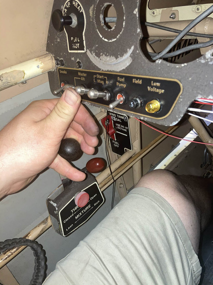
Engine starter engaged position - note that I can hit the starter and hold the throttle with the same hand
...when it dawned on me...
My three most important switches, L and R Mags, and Master, were set up with lockouts - you couldn't turn them on just by clicking them, instead, having to pull the lever first to move it to the "on" position. I mostly did that to protect from accidental too playful a kid in the cockpit.
But they weren't locked out in the "on" position!
Why is that important? Well, the Smoke and the Fuel Pump - the most operated switches on this plane - are right there. Note how their levers are shorter? If I accidentally hit the longer levered Master, or a Mag, switch, that would turn it off - with me potentially shutting down the motor. While a remote possibility, improving the situation would amount to just replacing the switches to the ones with lockouts in both on and off positions.
I don't know how I missed that when designing the original setup...
I decided to do it.
So out came the switches, I had to un-wire the terminals from the back. In went the order for three new switches with now correct lock-outs.
About a week later, I had them, and could proceed.
With left side wired up, I could tie it down. Mind you, access there is tight and from all kinds of weird angles :).
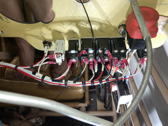
Tying left side
Some of those knots I did from the side. Some I did while sitting in the cockpit, using mirror as reference
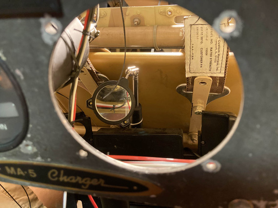
Look in the mirror!
Then, some "extreme soldering" to extend the panel lighting wires, that turned out to be a hair too short.
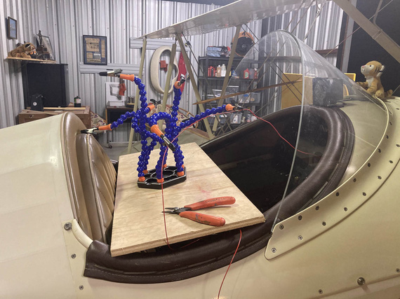
Extreme Soldering
For those lighting wires, and for the turn coordinator, routing took some fiddling with. My initial plan would've had them rubbing against the sides of the gauges, and I decided to bring them "out" and away - that's why I had to extend them, by the way.
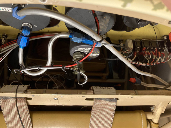
Lighting, and turn coordinator wires, test-tied
Note no padding on that pitot line: this is a temp, "sizing" pass: I am yet to finish assemble the back panel, and will add the right padding then.
The right side of the panel was much easier - it held much smaller, and simpler circuits, for lights and turn and bank.
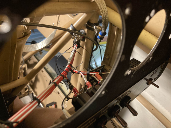
Right side
You can see the beginnings of the ground strap to bond the panel with the "side conduit", holding the fuse blocks and being one of the grounding points. In my original design, I had firewall, motor, "side conduit", and panel, as ground points - all bonded with those straps.
Here's the right side:
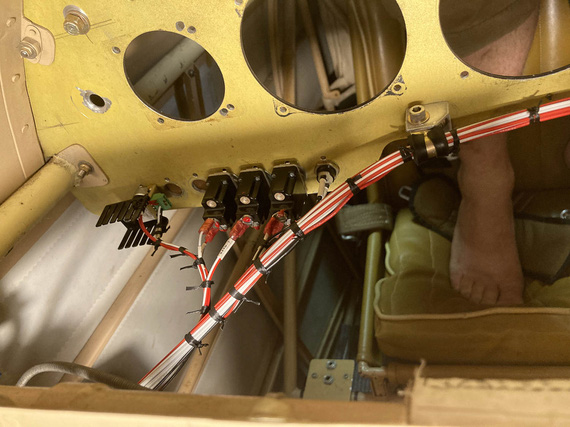
Right side
and the bonding strap
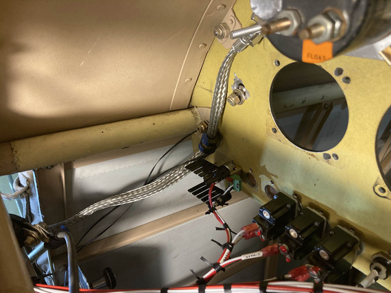
Panel bonding strap
(the bonding strap got enclosed in super flexible heatshrink just for neatness: this is a fit-up picture).
I also had some fun with ADELs right where the wires turn from the "side conduit" towards the panel. I had to clear and negotiate a couple bowdens, and the engine monitor harness was unwieldy.
I think that took a number of hours, just trying various setups, the final one that I really liked was this:
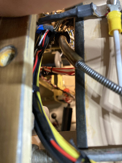
Engine monitor and carb heat bowden.
I replaced all the ugly zipties with lacing, of course :).
Meanwhile, on the outside, to keep the wires nicely separated, I spread them out in kind of a "fan" in the order they ran, back to front:
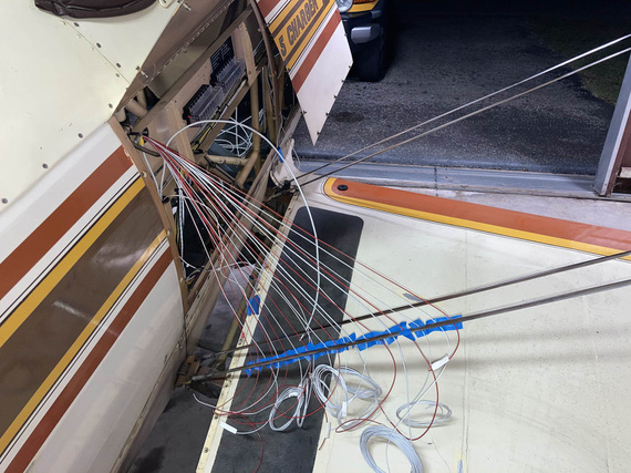
Wire fan
A day later, I replaced the tape with a comb. Yep, a cheapo $1 comb :) Worked out great.
And finally, before committing and continuing, I checked each wire for gauge, and proper circuitry.
Side Contuit, Part I
With all those wires sticking out, it was now time to start figuring out routing in the side conduit. All the wires that had to go forward had, well, to go forward.
After lots of fiddling, I ended up with this:
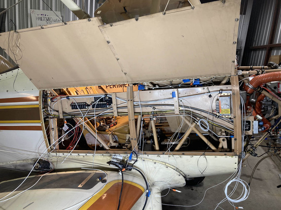
Initial stab at the side conduit routing
I had to clear all the brackets, and other sharp things. Ended up adding a couple more ADELs (and drilling holes in the conduit to accommodate). Also, reused some existing holes, made a few standoffs for ADELs and such.
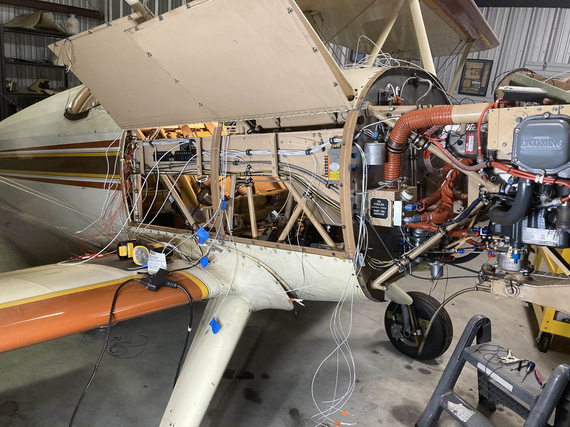
Another angle on the side conduit
And that was it for now. Now, all the other wires needed to join the main harness in the side conduit.
Front Panel
The most interesting piece in it was a Westach tach, that fed directly off of a P-Lead and required a .25A fuse. Glenn used a 1A classic glass fuse, but I decided to do it right. See, the thing is, if it fails "short circuit", that'd turn off the mag - I guess that's why the fuse is in there.
The tach would get another 20GA shielded wire, just like a p-lead, and I decided to join it to right mag's p-lead at the magneto - instead of splicing it into the p-lead running front to back in the side conduit.
But, back to the fuse. I figured, I'd build it into my connector that hooks up to the tach. Then, if blown, the connector could be rebuilt. Yep, it's more annoying than a regular replaceable fuse, but that circuit is not critical, and I had no room for a "regular" fuse block or holder.
So I got me a "legged" .25A fuse with a massive voltage rating (I forget what it was, but definitely above what a mag makes), and hooked it to a regular Molex pin.
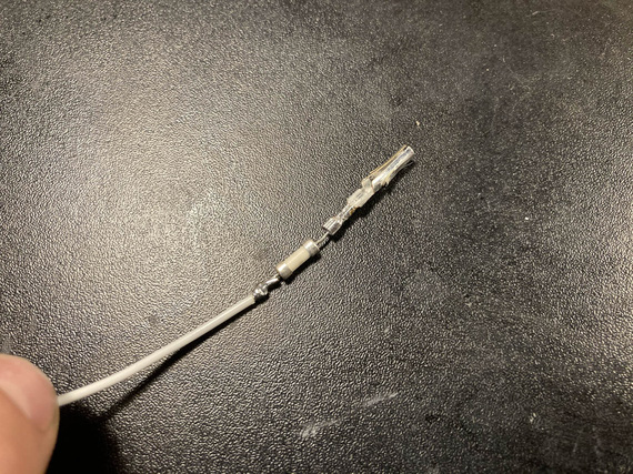
Inline fuse
Finished with SCL, it's encased in a plastic tube and is not moving anywhere. There's two layers there, actually: one around the fuse and the pin, and another around the housing and the inner layer.
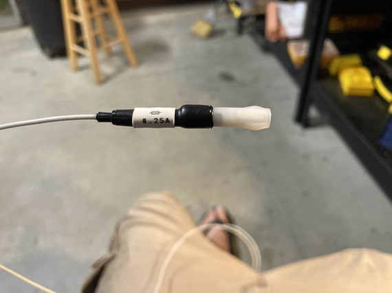
All finished
The final connector got set up like this:
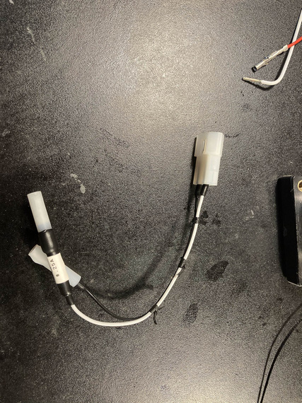
Inline fuse and connector
... and it goes on the tach like this:
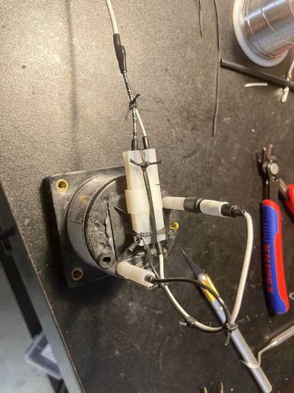
On the tach
The lead is just a regular pigtailed P-lead, of course. Notice how I like using SCL around individual Molex pins for added strain relief - that's because I can't produce good Molex crimps that I like; and I end up post-soldering them in addition to crimping. That strain relief ensures that soldered joint is firmly held immobile. Takes a bit of extra time, but I actually like that better than straight Molex crimps.
The rest of the front panel wasn't interesting, just annoying. There's only three circuits there: nav lights wires from the left wing run along the back of the panel to the right side where the conduit is, and then there's hobbs and tach, and that's it. It was just very annoying: with very little access, not being able to see things, and, being in the front hole, having to climb out and in every time I needed a tool I forgot to put close (when in the back hole, I can roll up a cart to it and have all my tools there).
Mirror was absolutely required.
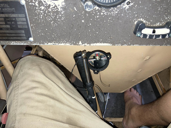
The only way to see things
I will admit to asking my dentist right around this time if he had a trick up his sleeve for this kind of mirror work. Of course, he said. Practice. Lots and lots of it.
Okay, so the front panel got done, and it's wires merged with the main harness.
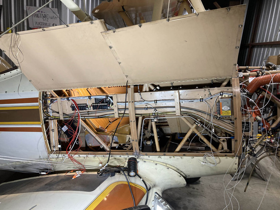
Front panel sub-harness joining the main
There, see, it's that small bundle going up and disappearing from view right in the middle of the "conduit"? That's the front panel sub-bundle.
Firewall Forward
The final set of wires to join the main harness were all the wires coming from the firewall side - mainly, transducers and other instrumentation wires, but also a couple wires for the voltage regulator.
This was precisely when I realized the mistake I talked about in the beginning - and ended up with less neat, and more tortured harness. Oh well.
I started up front, trimming and terminating my fat wires for the starter and alternator B-feed. Some more extreme soldering (to cap them), this time with a torch.
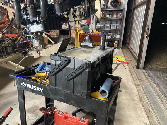
More extreme soldering
I tied up, and clamped the fat bundle to the motor: and apparently, didn't take a single picture.
Then, I had to figure out the diode for the Starter contactor - first of, it needed longer leads. There, instead of soldering, I used small barrel crimps from Molex along with heatshrink (I do use them where soldering is impractical, and I decided not to have soldered joints FWF).

Diode with leads

And all enclosed
And then, a simple ADEL to hook it up and hold it
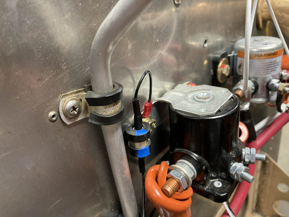
Diode all hooked up
And then, the ammeter shunt, and the sense wires. Those needed fuselinks - in liew of an in-line fuse. Simpler, and cleaner this way.
I tested them a while back, and am confident they'll work.
First, we take a wire 4 "gauge steps" thinner than the fused one (so 24GA for 20GA fused, etc). That goes into the "source" terminal.
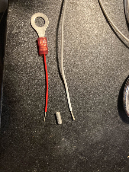
Beginning of the fuselink
Then, we hook it up.
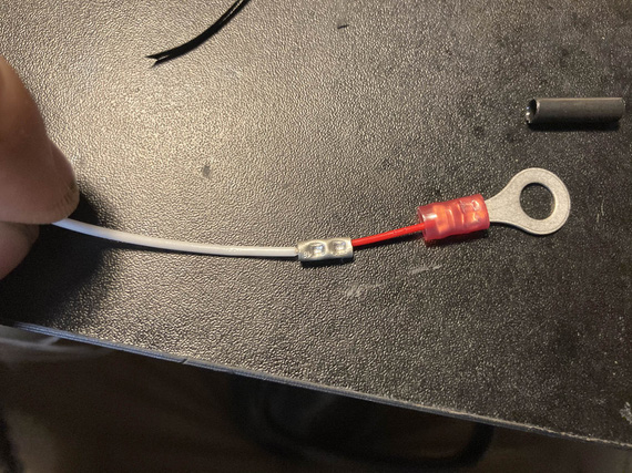
Hooked up to the protected wire
Then, some heatshrink over the splice, for strain relief.
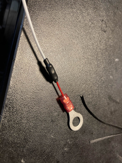
HST
Then, a bit of fiberglass sleeve to contain the "fire" when (and if) it does it's job, as in, burns thru the thinner wire that acts as a fuse in case of a short.
A bit of marking too. And a "cap"
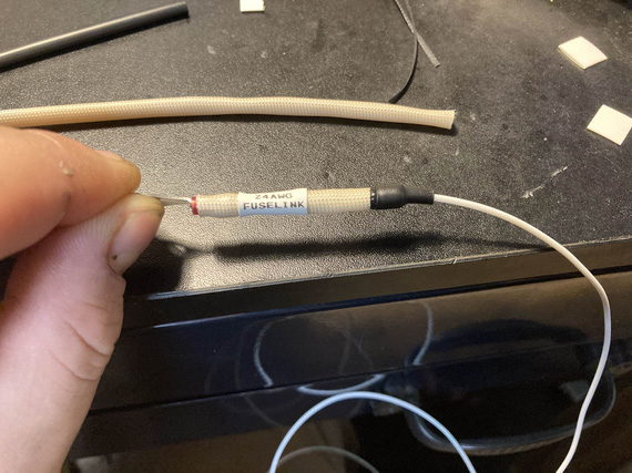
Capped and labeled
And finally, a couple knots to hold the sleeve better.
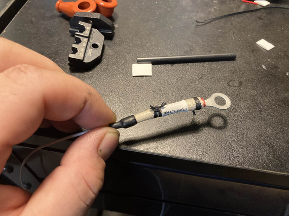
And laced
And finally, I finish installed all the engine transducers: pressures, and oil temp; and routed all their wires back into the side conduit and thru it back to the cockpit, adding them to the main harness. And that was that, for now - I plan to terminate them later.
Tail Light
I got rid of the belly strobe on the plane, because it was too heavy and too.. useless. Wingtip lights are gonna be the SkyBeacon and SkySensor from uAvionix (my ADSB mandate compliance :) ), and they have strobes: but they're not visible from the back. So I decided to replace the tail nav light with an LED nav/strobe.
Problem number one: no ground wire going to the tail light. For whatever reason, Remo decided to basically use the fact that the tail light is hooked up to the rudder with a pair of screws thru sheet metal of the rear rudder bow... I don't even want to begin to think what the ground path would be: hinges? control cables?
So, I needed a second wire.
Problem number two: it had to be one neat cable, and it had to be of a smallish diameter (Remo had an old 20GA wire, which is thicker than modern 20GA tefzel wire).
I decided to use a chunk of 20GA shielded - same ones I used for p-leads. Technically I guess you're not supposed to do that, but it's very far from all the antennas and I'm crossing my fingers that it won't create too much problems. Thickness was spot on.
So, I soldered the new piece to the old wire, and fished it thru using old wire as a pull. That part was scary - if that didn't work, I would've had to cut holes in the rudder to get a new wire thru.
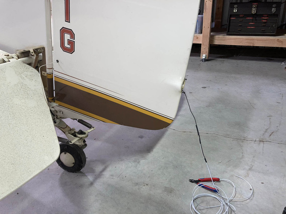
Fishing a new wire thru
The tail light shipped with a small Molex. Why not?
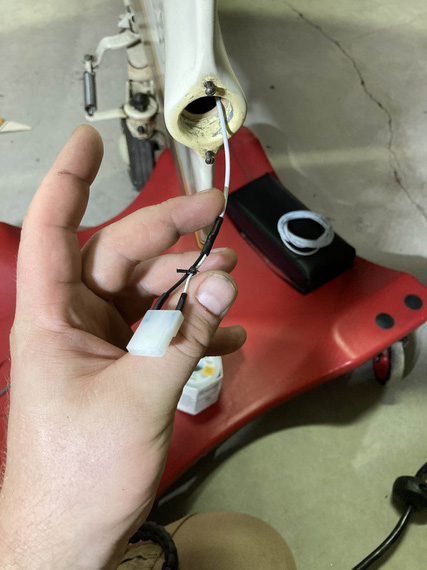
Connector terminated
The other end went onto the light, and everything got hooked up
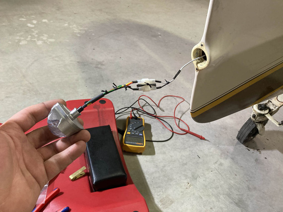
All hooked up!
On the other end (on the tail fin side) the wire went into a hole on the inspection cover, and had to join the wire coming from the front. And I had to have the ground there. You can see that area right behind the elevator on the "fishing wire thru" picture.
Problem number three: nothing to hook up the ground to in that area. The only option I figured out was to use one of the rivnuts that are attached to the tabs welded to the frame, hoping that there's no corrosion there between the aluminum rivnut and steel fuselage. I figured I'd use a way too long a screw thru one of the rivnuts when attaching that inspection cover, and then pull the ring terminal onto it, and secure it against the back side of the rivnut with a nut and a washer. Ugly? Yes; but I didn't have any more options. Really, the right way to do that would be to run two wires from the pilot panel all the way back, but.. I'd have to start cutting fabric for that.
So, I attached the positive to the wire that was already there, terminated my ground, hooked everything up, hooked up some power, and...
Nothing.
A bit of debugging showed that... ground was the problem. Damn! I picked the wrong rivnut, I guess - it had corrosion. The one right on the other side though showed the right voltage when measured against the positive lead, so I just moved everything to the other side, and...
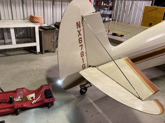
Let there be light!
Side Conduit, Part II
At this point, the main harness looked something like this:

Main harness: complete, but not terminated
Now was the time to go thru it, cockpit to firewall, and terminate all the fuseblocks, and tie and zip everything up.
First, conduit, cockpit side. Lots of crossing things, lots of padding for bowdens where they cross the wires (I used the right sized vinyl tubing from my local friendly Aerospace Depot, and lacing to tie it).
Engine monitor harness got covered in tube for quite a distance - there was no way to keep it off and not rubbing on the conduit.
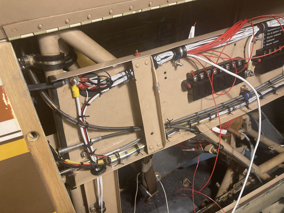
Cockpid side conduit
Fuse blocks got their placards. No, Mr. D., I am not doing brass placards again!
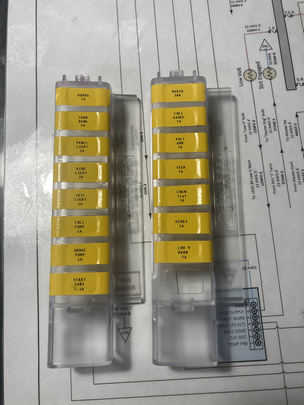
Fuse block covers placards
And then, slowly, methodically, every power wire got it's ring terminal. I added a bit of a "service loop" and used a ruler to try to keep each next wire exactly the necessary amount longer to reach the next terminal screw... Didn't work out too well, but close enough.
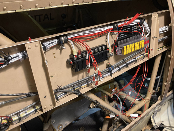
Rings!
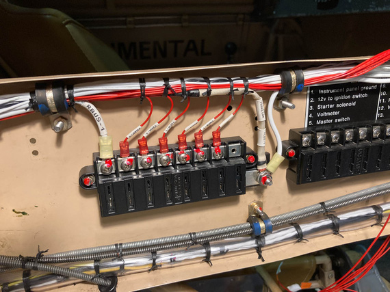
Tied up and hooked up
Another side got the same treatment, and then...
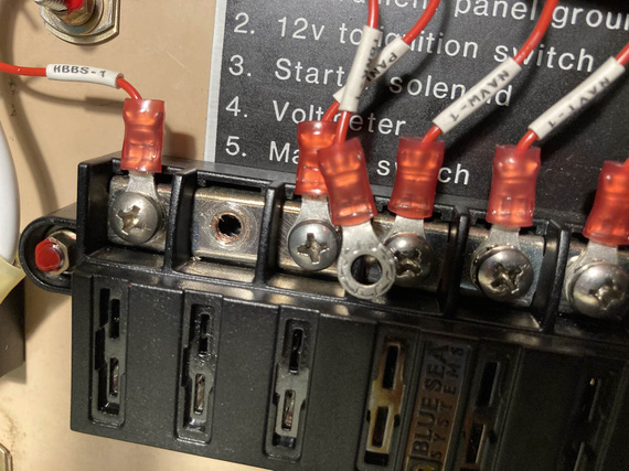
?!?!?!
Did I just strip a terminal block hole?? Yep. I did. I blamed a bad block and definitely, positively, absolutely not my overtorquing the screw. Nope. No overtorquing. For sure!
So, had to get a new block. They're $35 so I figured I won't try to repair this hole to use an upsized screw....I'd spend more money on shipping small-headed #10 screws (the screws in the terminals are #8 but with small "oval" rather than "pan" aviation style head, so I'd have to get me some decent screws from McMaster.. by the time I'd be done, it'd be close to those $35).
So, fuseblocks. From there, it was just turning everything pretty.
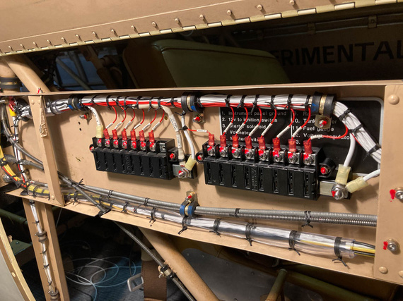
Both fuseblocks done and tied
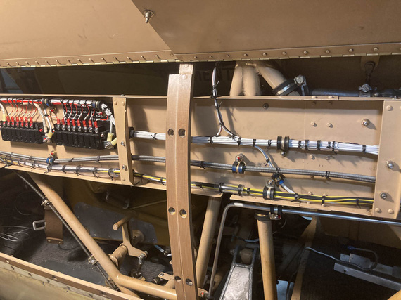
Mid section
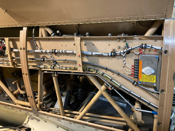
Voltage regulator
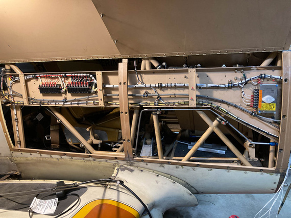
The whole thing
Sorry, couldn't resist doing a "before" picture.
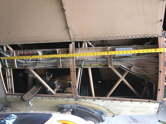
Before
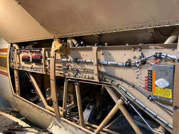
Jack likes this!
It at first you don't succeed, well, so much for skydiving.
Up ↑
Engine Monitor Wires
... firewall forward
| On: | May 01, 2020 |
| In: | [Chickenhouse Charger] Electrical Rebuild |
| Time logged: | 7.6 |
| Tags: | 6781G, MA5 Charger, electrical, fwf, engine monitor |
This was a small project to wrap up everything I could do firewall forward before moving on to the panel and main wiring.
I wanted to clean up the engine monitor probes harness. When Glenn installed it, he used zipties everywhere (and actually everything on the plane was ziptied). Nothing wrong with that, except where zipties were used around motor mount and the like without any cushioning.
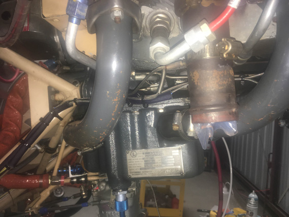
Probe wires with zipties
But last I checked, zipties weren't used in the 1930s. No, in the 1930s grass was greener, trees taller, water wetter, and Real Men used wire lacing to tie their wiring harnesses together.
And using adel clamps on round tube is just good karma.
So, I re-did one side first.
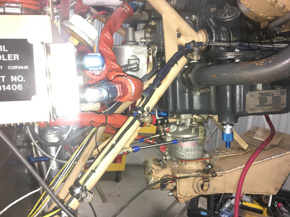
Properly laced and mounted
Much better isn't it? Those wing nuts are temporary - I will replace them all with real ones when finishing up FWF much later.
I did the other side, though didn't tie it up yet - there will be more wires joining that branch later, and I had to wait until they were done. But, I did set up all the adel clamps - about 4 pairs of them total.
Next, came the carb temp probe. I had to extend it's wire, and hook it back into the main harness. I repositioned it a long time ago because I ditched the Rotec TBI, and the old wire was just a touch too short.
I spent quite a bit of time making sure that it's a thermocouple, and that I can reliably extend it - with same material and type thermocouple wire. I did some basic tests with extending it and making sure it shows reasonable numbers. It did.
I thought a couple times about ditching it; but decided to keep it if I could, and my tests showed that I could do that.
Mounting and routing ended up looking something like this:
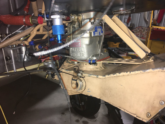
Carb temp probe wire
From there, it'd go straight to the motor mount (towards the firewall), and join the engine monitor harness.
When extending the thermocouple, the easiest thing to do is make sure that the joining thermocouple wires mesh together - this way, you're not introducing a section of a dissimilar metal between two segments.
To do that, I used simple Molex "barrel" butt splices that allow you to put one wire on top of another and crimp around. You then heatshrink the joint. In fact, I'm starting to like them, and am thinking about using them instead of the usual AMP butt splices with nylon insulation. They are much cleaner and compact, and heatshrink I use here (SCL) provides ample strain relief (it shrinks to hard plastic, and glues itself to the wire).
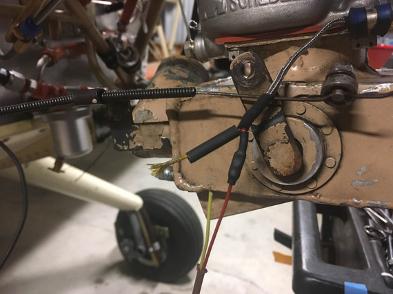
Extension being put on
I shrunk each crimp individually, and then another chunk around the whole thing. The whole thing was set up to be held by a second clamp (you'll see it in the picture a bit further down).
Back when I installed the CGR-30 on the Cheetah, I encapsulated all the probe wires into fiberglass sleeve, and here it'd fit perfect - to support the lonely wire spanning about a foot to the motor mount.
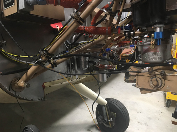
Fiberglass sleeve
I also used CGR's "barrel connectors" to hook up to the harness end. They have the wires "mesh" together, and fix them with a grubscrew, making the whole thing removable. Not sure when I'd want to do that, but I wanted to have an option.
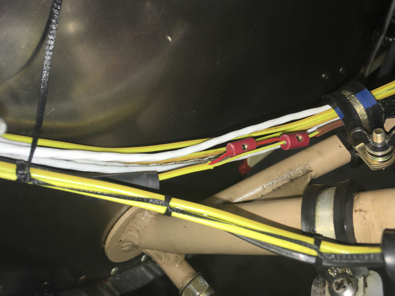
Barrel connectors hooking up to the main lead
Before closing it up, I tested everything. The probe had to be in the carb, so the best I could figure was to check if the ambient reading was good, and then heat it up and make sure that was reflected.
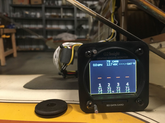
Testing
That was good enough for the test.
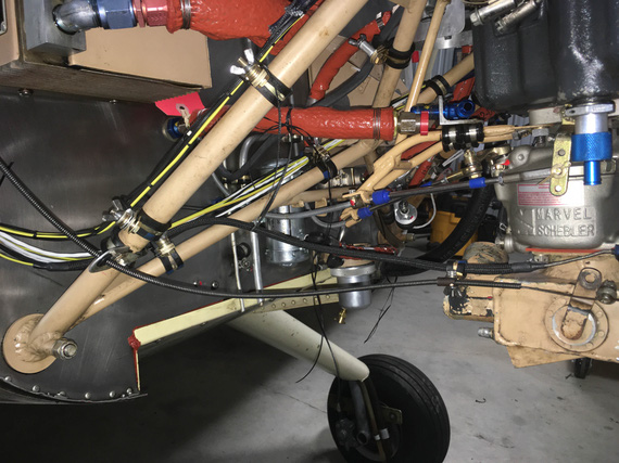
All closed up
Turned out pretty nice methinks - and I didn't have to lose the probe. The joint between the extension wire and the probe wire is very close to the adel clamp holding the fiberglass sleeve to the airbox, on the right side - and remember, it's in hard plastic that the heatshrink that's under the fiberglass sleeve turned into - so I'm not concerned about the joint failing there.
When a forecaster talks about yesterday's weather, he's an historian; when he talks about tomorrow's, he's reading tea leaves.
Up ↑
Fat Wires Firewall Forward
basic setup
| On: | Apr 30, 2020 |
| In: | [Chickenhouse Charger] Electrical Rebuild |
| Time logged: | 29.4 |
| Tags: | 6781G, MA5 Charger, electrical, alternator, starter, contactors, fwf |
Fat wires firewall forward. Battery leads, shunts, alternator, contactors, and the like.
I was doing them along with the fuel hoses mostly, in between waiting for shipments to arrive.
Mounting the Current Limiters and the Shunt
They were to take place of the old voltage regulator, onto the same mounting pads. I needed a backplate...
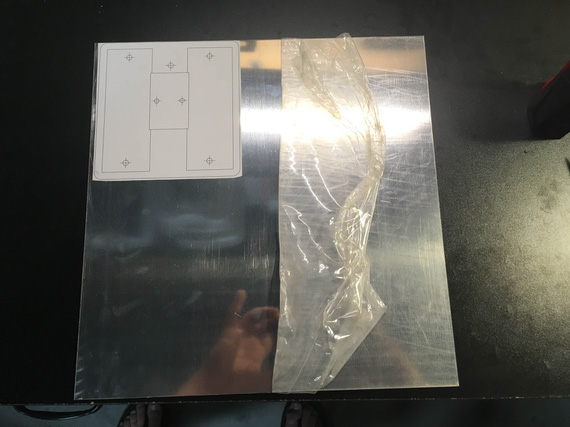
Pattern
...and a very basic one at that. Basically, a "hole pattern adapter".
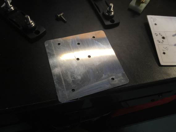
Cut
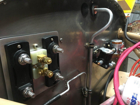
Mounted
I also needed to plug the nearby hole left by the removed mechanical tach cable. That one needed a large plug, and, as before, I decided to use a pipe plug with straight threads. It's nice, light, and aluminum.
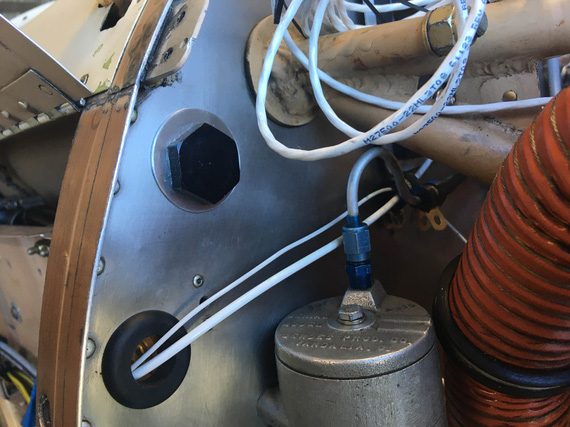
Tach cable hole plug
There, the black one. Above the grommet with a couple wires.
That washer took a couple tries to make BTW. First one was functional, but too ugly.
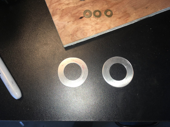
The washers
Plugging the Holes
There were some more holes left after removing some old things. They were for #6 or #8 screws; and I could barely access the other side (fuel tank that's right behind the firewall makes it super hard).
Instead of attempting to maneuver nuts back there, I wanted to try something along a rivnut.. but a bit better. Steel.
Spruce sells these steel "nutserts", which seemed to fit the bill. Got a set, with install tooling.
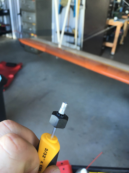
A nutsert with an installation nut
I had to enlarge the holes on the firewall a bit to fit even the smallest nutserts; and used #4 screws to "plug" them.
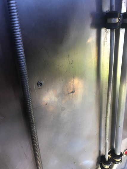
Nutsert installed
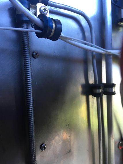
Nutserts with screws
Fat Wires
The contactors got mounted and torque sealed (of course I forgot to add a diode jumper to the starter contactor, will have to add later). Next, came figuring out the alternator wire and battery contactor -> shunt jumper (main buss feeder from the battery basically).
Initially, I thought I could route the alternator wire on the right side of the motor; keeping the starter on the left (remember, the firewall layout on this plane is reversed of sorts - with battery and oil cooler having their locations swapped and producing all sorts of grief due to that).
While not bad, holding the alternator wire on the firewall would've required more holes, and it'd go straight down, at 90 degrees to the main harness on the firewall (going left to right), kinda "crossing" it under. So I gave that idea up pretty quick, instead deciding to run it along that main harness - neatness and 1 less hole/clamp instead of a shorter by about a foot run.
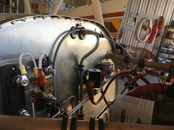
Initial alternator and starter hookups
Alternator wire is the white one going into the ANL current limiter, and starter wire is the red one joining it after coming off of the starter contactor (black) there.
And then, I needed the battery -> starter jumper. That was the spot to hook up the buss feeder too, with other end on the shunt.
I made this fancy thing...
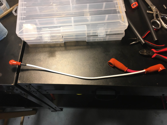
Contactor jumper and buss feeder
... and of course, a mandatory pile of shame...
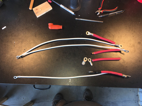
The Pile of Shame
Clocking of terminals is critical on these fat wires. If you're doing two wires, relative position of them in the terminal is critical too. You lose concentration for one moment and clock them wrong; and you're redoing the lead.
The first one I didn't like the crimps on.
The second one I messed up the clocking on.
The third one (bottom one) is the good one.
Mr. Max made a comment that it's the music that's distracting me (he was busy building his "water system" out of the old fuel system hoses and fittings I took out at the time).
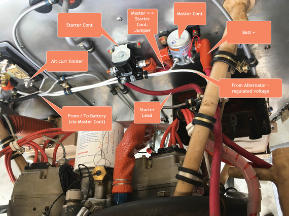
The initial setup
I did not like this. See how tight that Master <-> Starter contactor jumper is? It was very tight. The rigid alternator wire hooked into the ring on the master contactor side was too tight too (that adel clamp that I needed to hold stuff under the starter contactor had to be there - there will be other wires bundled there later). It was so tight that it bent the ring when I attempted to set it up.
No, that wasn't good at all.... hmmm..
Aha! I did a similar trick with the gascolator! Reverse the flow.
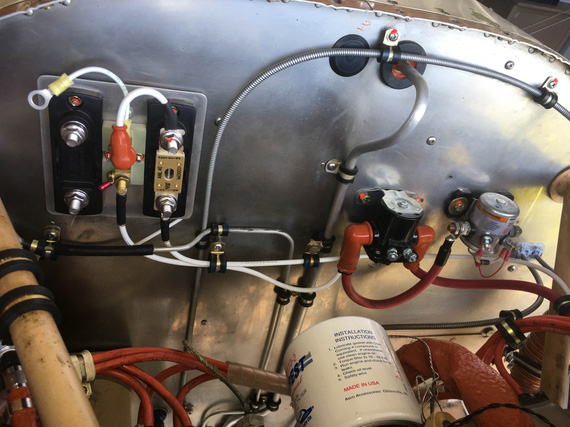
Flow reversed starter contactor
Much better! All I did was swapped the jumper from the Master contactor, and the starter lead on the starter contactor; and, while that made the fat red wire jumper much longer, it made the whole setup much, much cleaner. It made the buss feed wire a bit less pretty, arguably, with that weird "dip", but there's no avoiding it. I'll live with that.
The pile of shame grew.
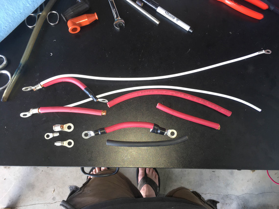
Growing Pile of Shame
By the way, here's how a crimped end looks up close.
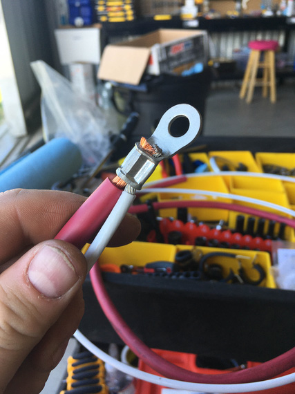
Crimped ring
Even with heatshrink, I had these thoughts of water weeping in between the strands on the ring end, and staying there, and slowly eating up the wire. Probably a non-issue; but it didn't sit well with me. So I used that as an excuse to whip out my small soldering torch, and add "solder caps".
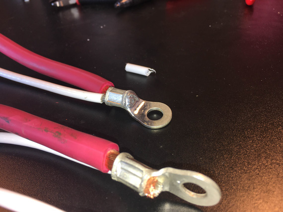
Solder cap
Much better and neater, don't you think? Solder here acts as a filler between the strands and to "tin" the bare copper wire of the welding cable I'm using for those fat red wires. Much; much cleaner and prettier this way.
Ground Strap
This plane didn't have any. The battery was grounded to the motor (good - the biggest current demand is from the starter). The motor wasn't grounded to anything else at all, making the current flow thru probably the control cables and fuel hoses to the rest of the plane. Not good.
So, one was needed. That took more thinking and fiddling. I had a plan initially to ground the battery to the motor and the motor mount (Grummans do something similar - battery to firewall; and motor mount to motor) - but I wasn't sure about how good a connection there is between the motor mount and the firewall. So I decided to jump the motor to the firewall - a very common setup.
Simple braid will suffice.
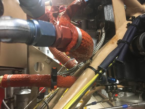
Braid - one end
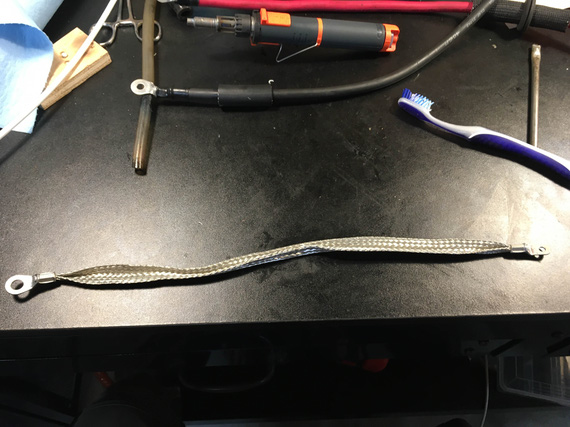
Braid done
I used a super flexible Raychem SFTW tubing and heatshrunk it. Doesn't affect the flexibility, but protects the strands a bit.
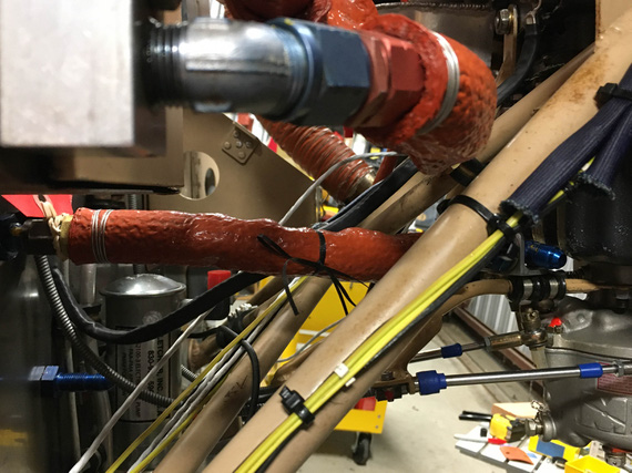
Braid installed
Battery Box
Battery leads were easy to make. Had to fiddle a bit with grommets (holes in the box are much larger than wires, and I had to use a "hose section around a wire in the grommet" trick to keep the wire tight and nice.
The battery box was another matter though.
Glenn had replaced the original large ("standard") battery with a small Odyssey - and took out the space with a bunch of chunks of random foam...
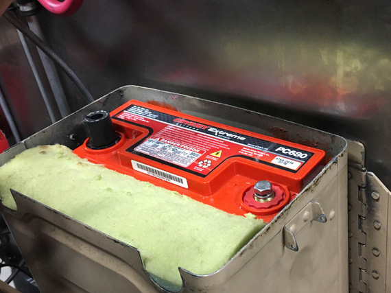
Foam
The box had "dimples" for the battery to stand on, lifted off the bottom (the bottom was made into a funnel of sorts that ended in a drain - setup for an old school battery that could leak acid). Those dimples were sized for a full size battery, so Odyssey couldn't stand on them.
So, .. ahem.. the solution was?
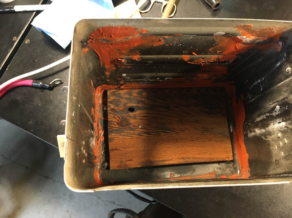
Bottom
Yyyyeah. No. Come on now.
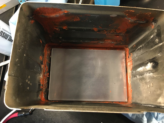
Proper bottom
And that chunk of whatever it was? Belongs here:
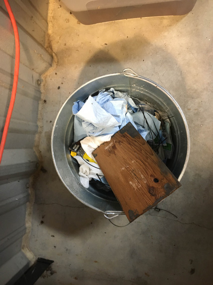
Right there
Now, the checks...
I hooked up the leads, routed them out of the box, and closed it up, only to realize that the battery was loose in the "up and down" direction. Not good at all, but the solution was simple.
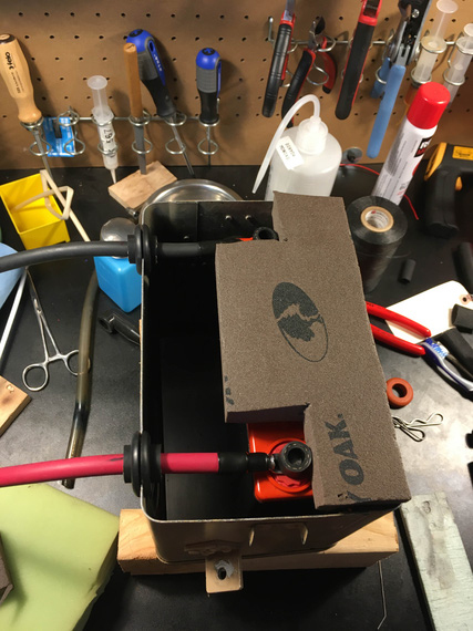
Mock up
I mocked up something quick out of some foam I had around, and closed the lid. Much nicer! No more bouncing. See, I didn't want the battery to hit the top and be bouncing if the airplane all of a sudden went to <0G (in turbulence, trivially possible - and it is aerobatic after all!)
Ordered some foam from McMaster, and padded the top of the box, and the battery sides.
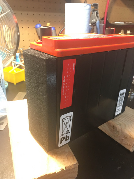
Battery sides padded
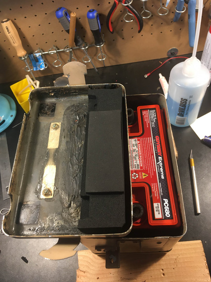
Box top padded
Now, the battery was sitting solid. No more bouncing.
And with that, I moved on. The main layout was done - the rest of tightening, tying, and strapping has to be done when all the wires are in, close to the end of this rebuild.
"N07K you look like you're established on the localizer and I don't know the names of any of the fixes, you're cleared for the ILS approach. Call the tower."
-ORD ATC
Up ↑
Tying Loose Ends
...fuse blocks, and oil cooler bowden
| On: | Feb 16, 2020 |
| In: | [Chickenhouse Charger] Electrical Rebuild |
| Time logged: | 3.7 |
| Tags: | 6781G, MA5 Charger, electrical, cables |
A couple things have been always on the back burner - fuse blocks, and finishing up the oil cooler bowden hookup.
In between waiting for completion of The Thing I Am Yet To Write About, finally, checked those off the list.
Fuse Blocks
Location was figured out a long time ago, and I just clamped them in place, center punched the holes, and drilled them.
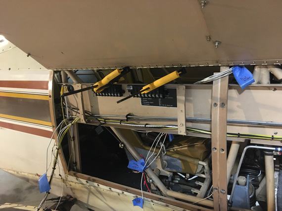
Clamped in place for hole marking
One little bit was to figure out the exact fastener lengths and washer stacks, because the right one had it's right (forward most) end riding on top of a reasonably thick aluminum placard you will see much better in the following picture.
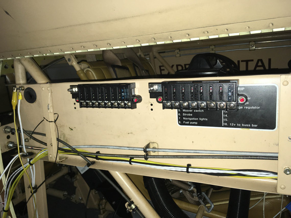
Fuse blocks: mounted
Done! Done?
You are forgetting, my Dear Reader. We here are in the misery business. Look carefully at the curvature of the fuselage. Imagine the side panel, open on the pictures, closed over our "conduit", on which the fuse blocks are installed. Do you see how the available "depth" will be bigger in the middle of the conduit as compared to the top?
Yep.
Of course, the panel won't close. With fuses installed, they would rub on the side panel. Not Good.
But relocating them down? What's the problem? Bowden cables, of course! I'd be too close to them, and I wanted very much to isolate my wire bundle and my bowdens; but even if I didn't, I still won't have enough room there for a terminal, and a nice 90 degree "turn" for the wire to go sideways (either towards the panel, or towards the firewall).
Solution?
Well.. there weren't any good ones, so I ended up taking the best of the crappy ones.
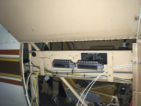
Final fuseblock mount locations
Not ideal, because they're flipped over - so technically, condensation can run down and into the fuse socket. Not a good situation to be in, but I can't do anything here. I guess, inspecting this area for corrosion is going to be on my Regular Maintenance List.
Oh, and I ended up with four extra perfectly drilled and deburred holes, right in the passenger's cockpit. That's what is on the other side of that "conduit".
I guess, I will attach a placard to them stating that those are "hole samples" or something (my friend Dick Gossen placarded a missing screw in his instrument panel once, so I figure I am allowed as well).
Oil Cooler Bowden
When headscratching about, and later installing the voltage regulator, Oil Cooler Air Shutoff Valve bowden was relocated (and because of that, I had to use a longer Bowden, which, gladly, I had an extra of after removing the Rotec's Throttle Body Injector).
All that was left was cut it to size, and install it into the valve's pivot arm.
Cutting bowdens? I don't know, I think it's easy. Pull out the actual control wire, and use bolt cutters. Push the wire back in, and trim to desired length.
Done.
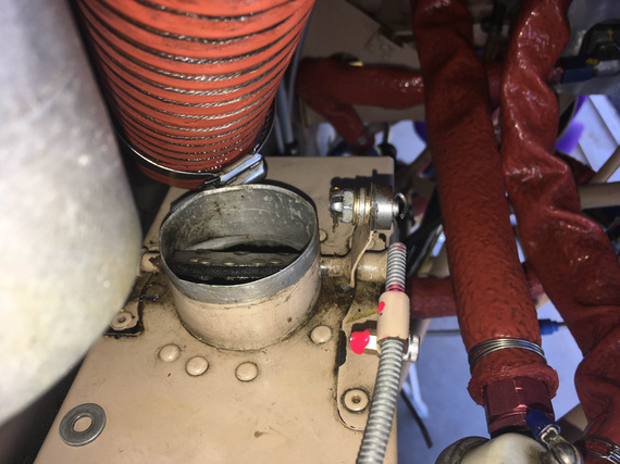
Here's the pivot arm.
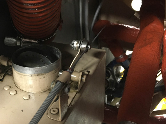
Oil Cooler Air Valve Pivot Arm
Notice the gap between the washer and the arm? Yep, the arm's too thin for the little bushing that's used here.
This guy:
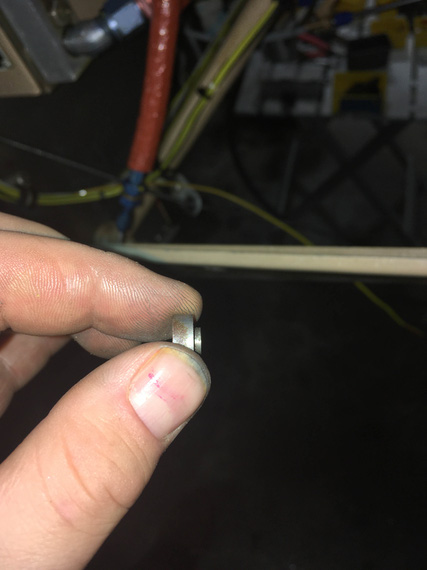
Pivot Arm Wire Bushing
No worries, we can file that shoulder down....
The other minor problem? The hole that clamps the "eye" that holds the bowden's outer housing in place was drilled too close to the place where the eye begins. Result? Flat washer was too big to lay flat.
Oh well.
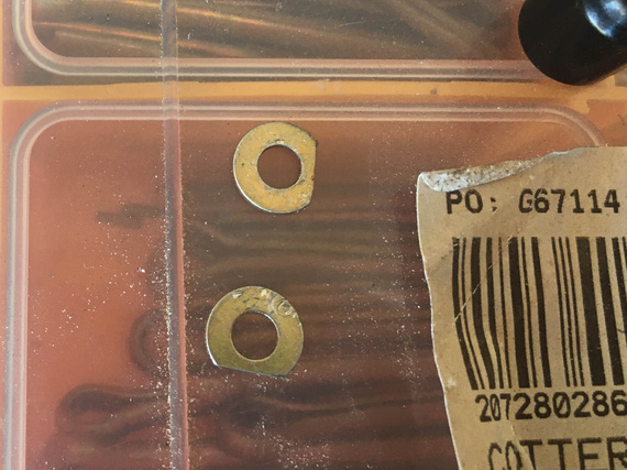
Custom washers
Put everything together, a bit of TorqSeal, a cotter pin, and we're done! (TorqSeal applied by a steady hand of a four year old, so please easy on your judgements, gentlemen!)
Done.
By the way, beats me why that oil cooler would need a shutoff.. It's way too small to begin with; and the SCAT feeding it is the whole 2 inches. I feel that I will excitingly find out how hot my oil gets in a Texas summer very soon....
Flying is not dangerous; crashing is dangerous.
Up ↑
Finishing Panel Prep
...placards and switches
| On: | Feb 04, 2020 |
| In: | [Chickenhouse Charger] Electrical Rebuild |
| Time logged: | 5.0 |
| Tags: | 6781G, MA5 Charger, electrical |
Since all my tools were already in the vicinity of the back hole, decided to finish doing everything around the panel in preparation for actually running the wires (which will come at the very end).
Placards
They were done quite some time ago. I center punched the holes in the panel for the #2 attach screws when test-fitting the placards, and left them at that.
Well, 't was the time!

Tappy-tap-tap!
That is a #2 tap, mind you! Tiny! I used a ratchet adapter; and didn't even need a ratchet - was just rotating it with my fingers. 1/2 turn in, 1/4 turn back. Slooooowly.

Done!
..and the placard went on nicely, too.

Placard set up.
Switches will be coming out one by one one last time later, to get wires attached to them, and to get all the hardware locked with washers/Loctite.
Harness Brackets
In the original setup, switches and fuses were on opposites sides of the panel (now both sides are occupied with switches), and the harness ran kinda loosely in between those sides.
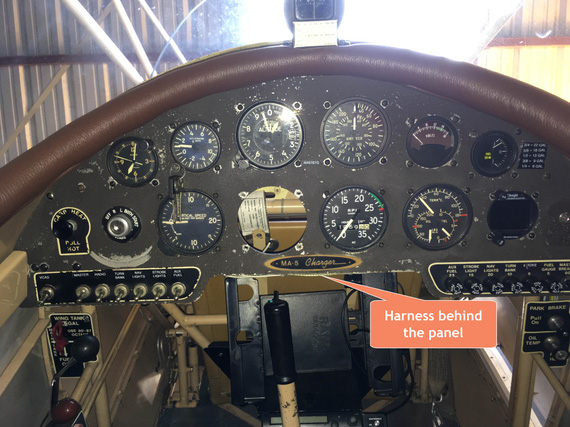
Old harness
I didn't like that bunch of wires not having any kind of support, and wanted to add something.
Having all those gauges clustered right above the harness, I wouldn't have had any room for the "raw" clamps attached to the panel in any reasonable way.. but, if I put together some kind of "standoff".. kinda like...
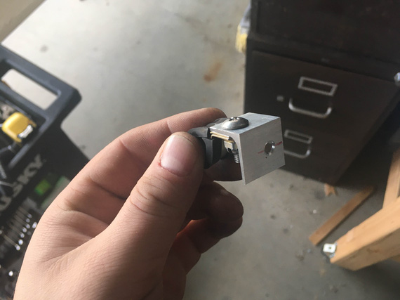
Clamp on the bracket
that! (This bracket courtesy of my Polish friend Mr. Wojciech.)
I made another one, and took some weight reduction measures, too.
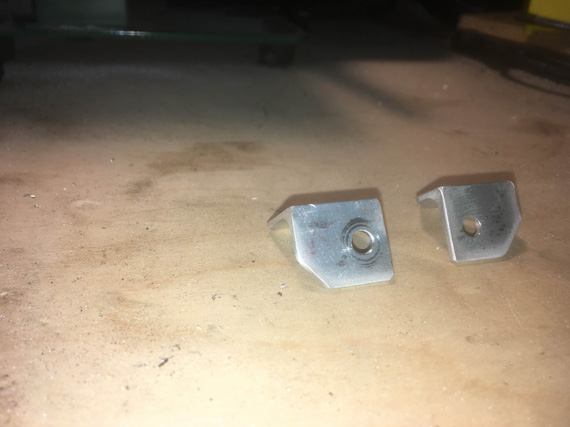
Brackets - cleaned up
Then, located and drilled the holes in the panel for them.

Using tape to mark out the holes
And, here they are. Notice how harness will end up below the gauges, not interfering with them.
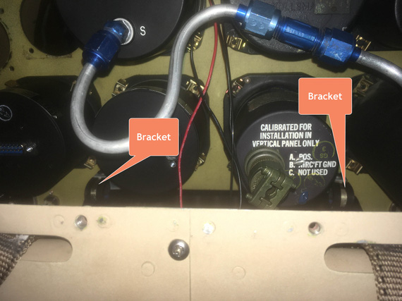
Brackets test installed
Here is how they look from the back, with some "test wires" run from the switches thru the ADELs.

Test installed with wires.
Nice, short, concise, and almost no misery this time!
Keep looking around; there's always something you’ve missed.
Up ↑
Light and Compass
...panel work
| On: | Jan 29, 2020 |
| In: | [Chickenhouse Charger] Electrical Rebuild |
| Time logged: | 10.5 |
| Tags: | 6781G, MA5 Charger, electrical |
While waiting for someone else to get back to me to help me finish <the thing that took last month and a half and is yet to be written about>, I decided to work on the panel a bit.
Lighting strip seemed like a nice place to start.
It's a simple LED strip that I planned to glue right behind coaming on the underside of the eyebrow. This way, it'd be invisible from pretty much any angle.
But, the wires! The wires in front of the panel, that have to go to the behinds.. No worries I thought, I'd make a small hole / slit in the top of the panel, also invisible - and fish the wires thru there.
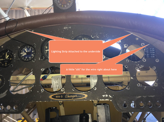
The Plan
That was the plan.
Reality, of course, decided to disagree.
The plan was to take out all the screws that went around the top of the panel, and tilt it "down" - so that I could use a drill comfortably to make the little slit for the wires.
Couple screws came out nice.
I think the third one came out like...
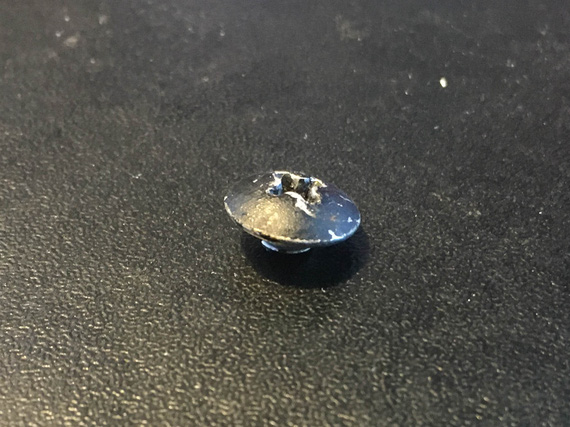
?!
Did I just bust a screw? I looked into the hole. Empty?!
Upon further examination, I found... glue? What? The screw head was... glued into the hole? That's a first.
After taking the rest of the screws out, I realized what happened.
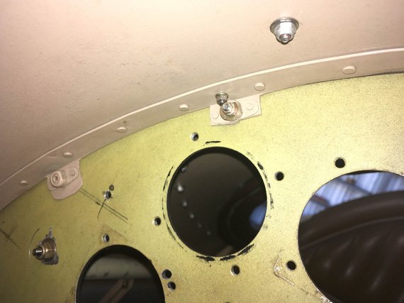
Backside of the panel
This is the back side of the panel. The panel is attached thru those little tabs and nutplates.
Notice the nutplates using rigid (not floating) style nuts? A slight misdrilling of the holes in the panel, and screws won't go in at all.
So, there were two "screws" that were just heads glued in - yep - and two more that used #6 screw in a #8 nut - the TPI on those is the same, and the holes were drilled sufficiently close enough to let a #6 screw pass thru; but not a #8. Le.. Sigh.
To top it all off, the panel won't fold down for me to get access to where I wanted to be, and to fish it out I'd have to take out the carb heat bowden cable that was attached to it. Too much trouble if I can avoid it (that carb heat cable would've been a 3-4 hour affair just by itself).
Plan B solidified; but first the panel had to be put back.
I ended up putting #6 screws into all the misdrilled holes (sorry, but glueing heads into holes is.. not my thing :)); but I installed nuts on them on the back. Effectively, set up like this the nutplates don't do anything - just add weight. See the picture above - it has the nut over that nutplate. That nut, by the way, was a pain to get in - see how close another nut is to it?
I think all the fiddling with the panel, screws, nuts, washers (losing a few of them and going on fishing expedition to pull them out of the guts of the plane included, of course), and trying to get it back in right took what.. around 6 hours?
The plan B, now executable after the panel was back in, was to route the wire under the eyebrow, and fish it thru behind the coaming to the "top" side right in the middle, where the compass was to be. It then would join the compass light wire, and go to behind the panel land.
So, the strip was glued, and the wire attached to under the eyebrow with HVAC duct sealing tape, ahem, aircraft grade glue backed aluminum sheeting from the local friendly Aerospace Depot.
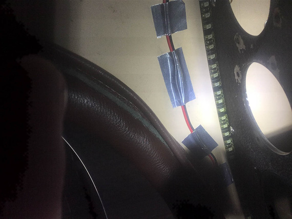
Strip glued - looking up
That picture's taken "from under, looking up". Ugly? Well, not too easy to make it pretty doing it basically blind with an inspection mirror the only view. Like this:
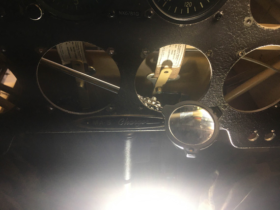
The only way to see it
The wire was fished thru to the "top side", and it was time to test.
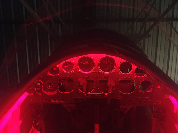
Lights on!
Pretty, huh? :)
Since I was working on that area, I decided to finish it off. Compass was prepped...
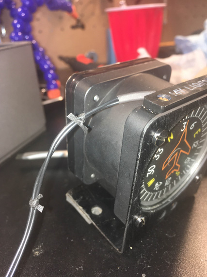
Screw those zipties!
... and installed.
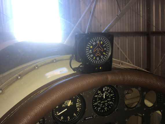
Compass installed
The compass bracket is pinning the compas lighting wires there, and ...
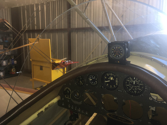
Other side (see the red wire)?
... the fished thru wire for the panel lighting strip (see the little red wire? that's it).
Done, and done.
"The first officer says he's got you in sight."
"Roger, the first officer's cleared for a visual approach runway 27 Right...you continue on that 180 heading and descend to three thousand."
-ORD ATC
Up ↑
Placards for Switches
...the biplane way
| On: | Nov 23, 2019 |
| In: | [Chickenhouse Charger] Electrical Rebuild |
| Time logged: | 20.7 |
| Tags: | 6781G, MA5 Charger, electrical, placards, etching, SWX |
This is all your fault, you know who!
...
Way back, when working on the new layout for switches on the panel, I was thinking about how to re-label them.
I had a nice Brady label maker, and was thinking about just printing and sticking some tags over existing, painted, lettering, on the switch placards.
One of the nights, when I was tired enough to do anything useful, I was playing with the stickers, and posted this picture here:
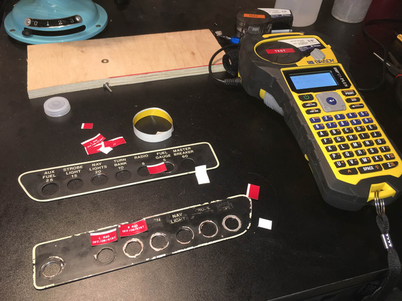
Playing with placards
The you-know-who-you-are, of course, wasn't happy (this gentleman is an actual friend of mine, not a silly voice in my head). "They will fall off", he said. "Can't you do something a bit more professional"? "Can't you draw them up, and order them to be custom made"?
Order?
Ha!
No. This whole exercise in airplane handling is to put yourself thru as much misery as possible. So the placards had to be made, not ordered. I mean, I could've ordered my electrical redone too, right? :)
I recalled that I read somewhere on Vintage Machinery that someone figured out a neat way to restore old data plates on old lathes and such. Looking it up, I remembered.
Etching!
The idea is basic - make a mask, transfer it to a piece of metal, soak it in acid, paint, sand - your recessed (etched) areas will keep paint, while the elevated (masked out) areas will sand out. This way, you get metal-on-paint look, and it's nice and pretty.
So, it has been decided - I will etch out my switch placards!
First, though, I had to figure out...
The Process
Obviously, SolidWorks would be instrumental in making the actual pattern. I wanted to make the placards out of brass, so that lettering would be yellow, and I'd paint them black, for the yellow on black final result.
First, the mask.
Searching around, it seemed that the most reasonable way to go about it would be to use Toner Transfer technique. Laser printer toner (at least on a good subset of laser printers) is basically powdered plastic. Printer warms it up, which makes it sticky - and toner then fuses itself to paper. It can be re-softened (and made sticky again) by a normal household iron or a laminator. I had both - an iron, obviously; but we also had a great "office grade" laminator in the office.
A lot of folks had success with glossy paper (glossy paper doesn't absorb melted toner, it sticks, but stays on top), but I, looking around, found a lot of good reviews of the PCB Fab in a Box system.
Not only the guy makes a very nice toner transfer paper which "releases" the toner when soaked in water (it works just like your model decals in plastic models, you soak the paper, and the top layer comes off), he also seems to have researched and cleaned up the process to minutia. For example, the toner itself is porous (indeed!) so he uses an extra layer of plastic to "fuse" the micro-gaps between toner granulas as transferred with another layer called "TRF Foil". He also did a lot of research into printers, toners, application techniques and such - and published a great handbook. Just for that alone, I wanted him to have my money.
So, I ordered the transfer paper (the one you print your mask on), and tried the first step - transferring it to a small strip of brass in a laminator.

Laminator with envelope with the workpiece

Transferred!
What's wrong with that picture? Riiight! I forgot to mirror the pattern :). Damn.
I messed around quite a bit with density, too. Just default settings were crap, obviously. Bumping up the density to max didn't help much. I installed a new toner cartridge, and that improved the density dramatically - while not perfect, it would've been workable, hopefully, with the addition of the TRF foil (and, if I saw any obvious holes, I could fill them with a sharpie).
Okay. But the basic test worked! The pattern transferred nicely.
Second time, I threw together another test mask with a couple of different fonts about the size I'd want on the placards - I was gonna transfer those to a small chunk of brass bar stock, and try etching.

Second pattern
With the help of child labor, patterns were cut out, and transferred successfully to the brass bar stock. I then applied the green TRF foil (that stuff that fuses the pores between toner's grains) to it.
Side note: the process manual from PCB Fab in a Box notes explicitly that Brother printers have a kind of toner that requires much higher than usual laminator's temps to melt. I have a Brother printer, but since I was able to do my first transfer successfully, I kinda decided to not bother - it worked, so I must be the lucky one right? Though I admit, I did entertain an idea of a new printer... ;)
On one of the evenings, I had a block of a few hours, and the weather was nice. I had all my chemicals (ferric chloride PCB etching solution and boxes of baking soda to neutralize it afterwards), so I decided to try the actual etching process.
I hooked up the test plate to a piece of closed cell foam (to float it on top of acid)...

Brass with mask hooked up
...set up a small plastic table outside the hangar...

The setup
...and went to town.
The idea was to try to get the ferric chloride to about 100 degrees F to speed up the process, so I did a hot water tub (hence, the little camp stove in my setup).
I'd have a large tub with hot water, and a small tub with etching solution in it, with the workpiece floating on top, hooked up to the foam.

Etch, etch away!
It took about 40-50 minutes, I think, till I was comfortable with the depth of etching. Every 10ish minutes I'd pull the piece out, and brush it with etchant to clear the debris that, I thought, would collect in small nooks and crannies (I saw a guy do that on one of the videos I watched).
After a decent etching depth was achieved, I pulled it out, and dunked it in soda to neutralize the acid.

Neutralizing
Then, lots of rinsing, while catching water into a tub. Acid, even neutralized, will contain dissolved copper, and just dumping it is not good. I was planning to keep the tub and let water evaporate, at which point I could just wipe off the powdery residue.

All cleaned up
After that, a rag with acetone wipes off the mask, and...
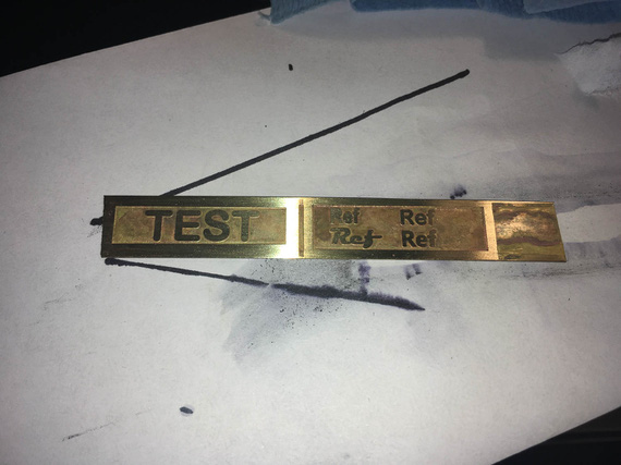
Etched!
The edges on the letters (basically, the edges of the mask) are very rough there. On these test ones, I started with a maroon pad, but quickly went to a 120 grit non-woven deburring wheel, which cleaned it up nice (and of course, messed up the letters - well, lesson learned, I won't use that aggressive a method on the real thing).
Later, when painting, I noticed that the mask was still porous, letting some acid in (I had some tiny "cavities" in random spots). It looked pretty good when applied. This would become obvious later, when I started adding color. I suspected the old drum, and decided to get a new drum for the printer - though in hindsight, I think this is, after all, the problem of me having the Brother printer (read on ;) ). Meanwhile, I ordered a new drum and a new cartridge.
And then, the paint.
I wanted "golden" letters on "black" background. I wanted to make the whole piece black, and then sand it on a flat surface - everything that was masked would have the black sanded off, and the rest would keep it, achieving the effect.
I wanted to try a couple different "make it black" approaches. One would be forced oxidation with something like a gun blueing acid, and the other would be plain paint. I had two test areas, which would allow be to try both at the same time.
So I blued one side....
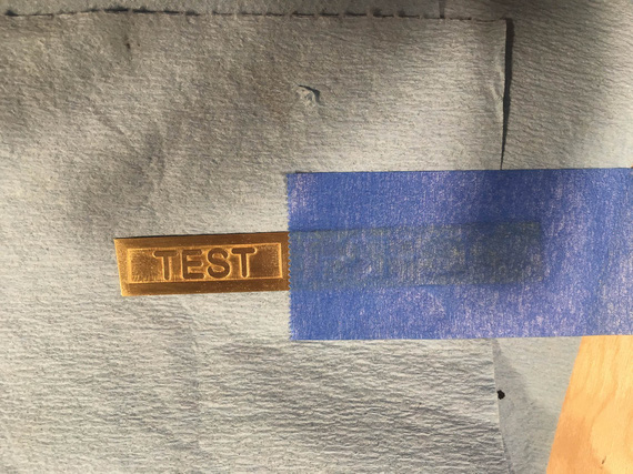
Masked
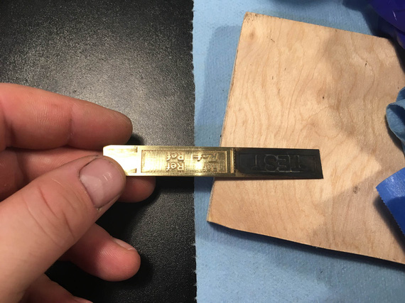
Blued with Brownell Oxpho-Blue
... and sanded it down.
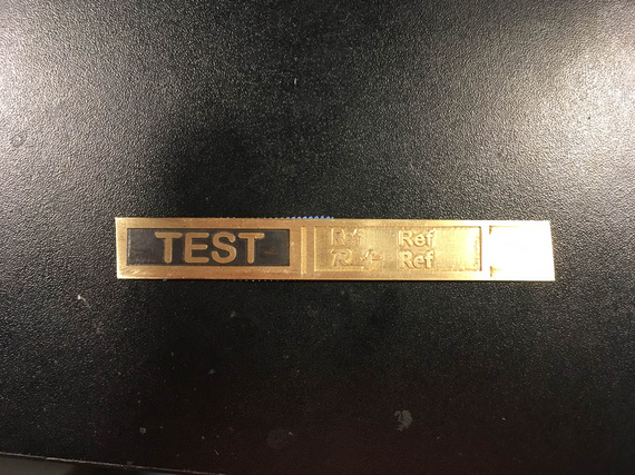
Sanded down
Couple notes on blueing. I tried Brownells Oxpho-Blue, and then later Birchwood Casey Brass Black. Both produce a layer of black oxide on the brass. There are a couple of problems, though.
First of, the etched surface is not perfect - and those imperfections are not really hidden by oxidizing, obviously. Second, and bigger, problem, is that that oxide is powdery, and can be rubbed off easily with even a paper towel, given enough elbow grease. I was afraid I'd have adhesion problems with the top coat (I was gonna coat the whole thing in clear to prevent tarnishing of letters), so I decided against it.
The other side I decided to put just your basic schedule of Rustoleum - primer, and flat black.
My kick-ass paint booth
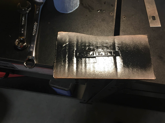
All done.
I waited for about a week with the Rustoleum side, and then sanded it down.
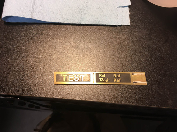
Rustoleum sanded down
I liked that side much better. However, the primer, being white, would show in between the paint and the letters, being noticeable. I decided to find some black primer - and meanwhile, coated the whole thing in lacquer, which I decided to use as a top coat.
Mistake! A few weeks later, lacquer started flaking off. Yeah, I learned the "no lacquer on top of enamel" rule. But it was flaking off on plain brass too, so.. lacquer was no way to go.
Just typing that, in hindsight, maybe there was some acid residue after blueing... but acid was dried, and I used acetone to clean up the blued side. But again, clear brass had lacquer coming off as well.
Worse part is, the enamel lifted and was coming off in pieces.
So instead, I did something that in hindsight I think was a mistake. I decided to look for a better paint solution, and very quickly arrived at epoxy, specifically, Klass Kote. It seems to be used by a lot of RC builders very successfully, I saw successful reports of brushing it, and talked to them, too. I was sold. Again, in hindsight... I think this was a mistake. But, read on. :)
The Actual Mask
To make the actual mask for the actual plates, I used my scan-and-draw-around-it Solidworks trick. I scanned the old placards, and sketched around them.
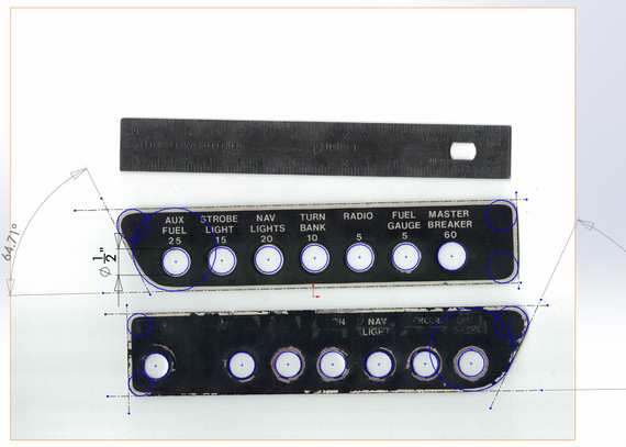
Sketch
I very quickly discovered that on one of them, the sides were not parallel; and the holes were all not on one line, and not evenly spaced! :). So, I made two versions - one all nice and even, and the other just like the old placards.
Using a bit of cardstock, I tried each of them on to make sure the holes are okay and such...
Trying on the pattern
Guess which ones fit better? Yep, the crooked ones! Straightening them out made holes not line up with holes in the panel, and one of them would interfere with some screws on the panel. Oh well.
Then, came quite some hours (that I didn't log to be honest) fiddling with the font and the layout. I decided to use "Magneto", the kick ass italic font out of the four I tried on my test etch.
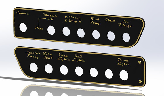
Plates with the cool font
But, the same gentleman who made me undertake this endeavor, argued that while these would look grand on a Cadillac, they have no place in an airplane. "Use standardized fonts!" he said. He did have a point. If it was not me in the back hole, and it was an emergency, readability, not style, is a prime factor. So, I had to remake them.

Plate with the boring font
Before actually committing to etching them, I wanted to do the final size and looks check with actual metal. So, I printed the things on regular paper, spray glued that paper to some scrap aluminum, cut them out, and drilled the holes.
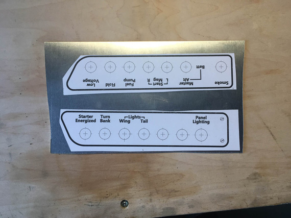
Test pieces
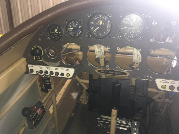
Left side
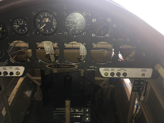
Right side
One thing became readily apparent - the lettering was too high up and rows were too close. Well, that was an easy fix on the model, I just moved the bottom row a bit down.
The hour X was quick approaching. I now had the twice tested model that fits, and all the kinks were worked out.
Applying the Final Mask
For material, I picked up a sheet of brushed "Marine-Grade" 464 .032" thick brass from McMaster (remember this, "brushed" - one side is brushed, the other is not).
On the final drawing for the mask, I replaced hole outlines with little "donuts" - thinking that those will make nice initial "center punch" marks for the holes.
When printing it, the toner flaked off the transfer paper immediately. "Bad sheet of paper", I thought. I also found the "Improve Toner Adhesion" setting, and enabled it. That made a nice print-out.
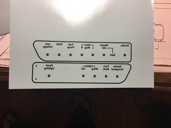
The final mask
Prepped my brass with good clean and acetone wash...
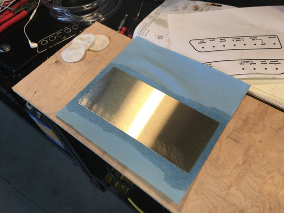
Prepping the brass
..made a nice pouch for feeding it thru the laminator..
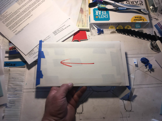
Pouch
..drove to the office, and started feeding the laminator with it.

Food for the laminator
On my test piece, I did 10 passes, so I did the same here. Pulled off the pouch, and...
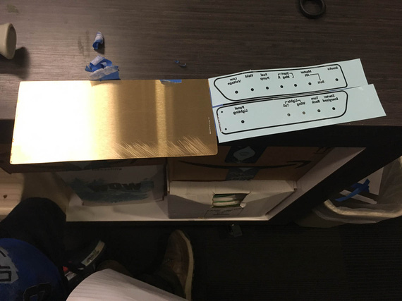
!??!??!?!?
What?! It worked before! A bunch of thoughts went rushing thru my head - more metal? Not getting it hot enough (but it was hot!)? Bad toner? Wait! YES! This time I used a completely new toner cartridge and new drum unit - to make sure my pattern has as little of those pinholes as possible (remember, I ordered a new drum and toner after my initial test etch?)
I went home, and compared the serial numbers on the toner I had success with with the new toner. The first few letters were different, as well as the few digits in the tail, which made me think it was a different brew of toner, and toner problem. So, I printed the mask again with the toner that worked before.
I also started thinking that the "Improve Toner Adhesion" setting I used might've caused mayhem. I also read a bit about that setting, and it seems that Brother recommended using it if the toner flakes off and if setting the paper type properly (ie, "plain", "card-stock", "thick", etc) does not help. So to prevent flaking off, I set the paper thickness to "thick", removed the "Improve Toner Adhesion" setting, printed it again using the toner cartridge that worked before, and went back to the office...
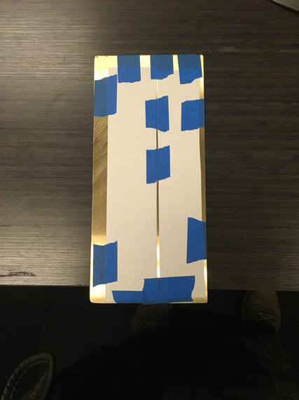
Second attempt
This time I didn't use the "pouch" of paper I typically wrapped around to protect the brass and help the laminator pull it thru (the laminator I was using had a problem with feeding first 2-3 inches of brass - it wouldn't pick it up - so I used paper as the "carrier", which alleviated the problem). I thought that maybe paper was preventing some heat from being transferred well, and got rid of it this time.
Same problem!
What the hell?
I took the laminator home, determined to run a bunch of tests (it was Sunday ;) ).
I had a couple of old masks left (I printed double the amount then, in case first try didn't work - so that would cover the toner/drum combo that I know have worked). I printed a couple of new ones - new drum/old toner, and new drum/new toner.
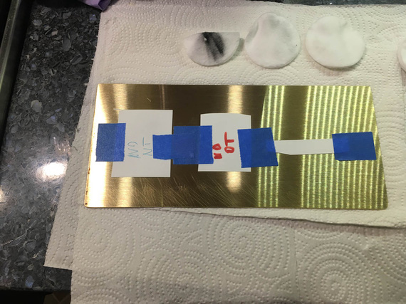
Test pieces
I also changed the settings again, for the two new prints I made.
As I mentioned before, when first printing the final mask (the one that didn't transfer), I had it's toner literally flake off the paper in some spots. "Hmm, I thought", and re-printed it, using the "Improve Toner Adhesion" setting enabled. That made the paper go thru the printer much slower, it came out much hotter than usual, and the toner adhered well.
On the second try (the one that didn't transfer either), I read a bit about the "Improve Toner Adhesion" setting, and decided to instead try to change the paper type to a more appropriate one - so blaming whatever "Improve Toner Adhesion" did for not transferring of toner, and blaming "thick" not being set on the first try causing toner to flake off, I set "thick" for paper type - which, again, caused the same effect - slow feed, hot paper, good adhesion.
And then, when finally doing a systematic attempt to figure out what's wrong, I remembered that on the very first test masks (the ones on the test piece of brass buss bar stock), I didn't tweak any paper settings at all.
"Slow Feed", "Hot", vs "Fast Feed", "Colder". This time, I started guessing that maybe, higher temp did something to the toner that would then prevent it from being re-melted when fed thru the laminator. I decided to try my luck with "plain" paper type (fast, cold feed), and count on my luck in the toner adhesion department.
I lucked out - test pieces came out fine, and, with three test masks, thru the laminator we went again.. And again... 10 times total, as before.
This time, things definitely changed! First of, all three transferred equally, but they transferred equally... crappy.
So, we knew that we were onto something with the feed/temp settings of the printer affected by the "Improve Toner Adhesion" and paper thickness settings.
But, transfer was still crap.
And then, I realized one more thing.
I was transferring to the "brushed" (remember, I had a "brushed" brass sheet?) side of brass? Those "brush marks" are noticeably deep when you drag your fingernail across them. I suspected that, effectively, whichever pieces of the mask were above the marks, wouldn't touch any of the metal, and therefore won't stick.
OKay, but I can use the other side! It was cruddy, but a bit of the deburring wheel...
Wait. Go to the airport to polish the other side? Ugh.
Found a piece of steel wool we use to scrub dishes. Phew. That, under water, made the other side of brass nice and clean on short order.
OK, the moment of truth. Printed the pattern again, using the new toner/drum, now, when we know that toner/drum aren't causing my transfer problems, but rather, the temp and the feed rate of the printer are.
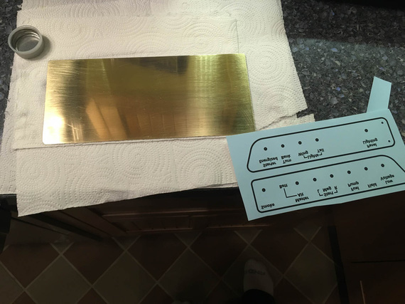
Will this be final?
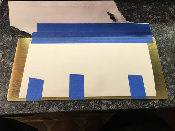
Attached to brass
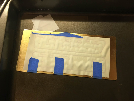
Soak after the laminator to remove the transfer paper
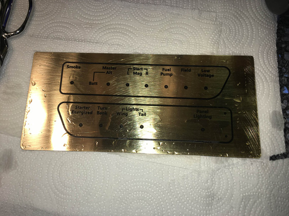
Transferred!
Phew. Okay. So, I guess, after all, Brother toner is finicky, just like the Fab-in-a-Box guys tell you, and mine is not special. I don't know why fast feed / low temp would even keep it transferable.. but... Well, the lesson I take from this is that I will be carefully considering the toner type when buying a new printer, when that time comes.
And then, the foil. I'll admit, I did a couple attempts with the foil. Yeah, and when I didn't like what happened on the first attempt, I had to re-do the mask (toner transfer, that is) yet again!
My laminator has serious feed issues. The foil is very finicky, and keeping it straight requires laminator to feed nice, smooth, even, and straight. My laminator needs to be "helped" sometimes with pressure pushing the plate "in".
Oh, well. After the second attempt, I realized that I probably won't achieve ideal results on such a big piece, and instead, used Sharpie to fix as much holes in the foil as I could find.
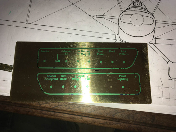
Final mask, and lots of Sharpie.
So, bottom line. If I want to make perfect, non-porous etches, I need to get me a good printer that will do what I need, and a good laminator that actually feeds things nicely. Later, later :).
I was planning to etch the following morning.
The Etch
The weather was great, and I relocated to the airport, setting up my "camping setup" outside the hangar...
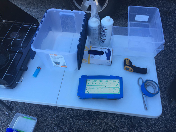
The setup
..put the plate attached to the foam into the tub, and went counting my 10 minute chunks..
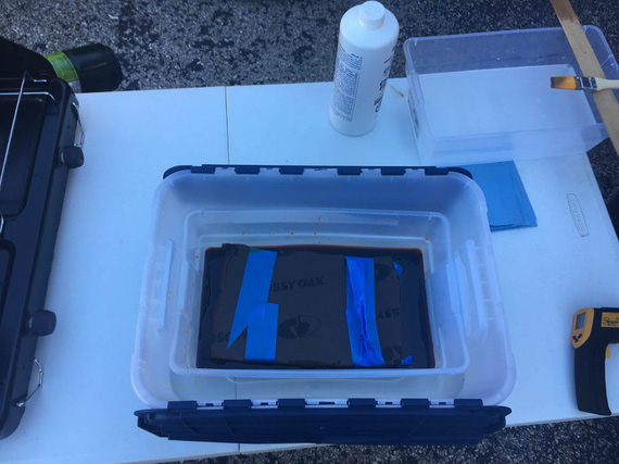
Plate in the tub of etchant
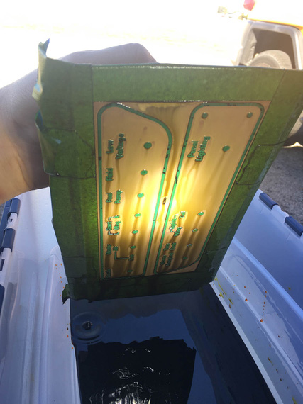
Etching is visible here
..it took about 90 minutes at 100F etchant temp to get about .010 depth.
To neutralize, this time I used soda with water, to make it get into all nooks and crannies better.
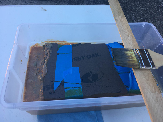
Neutralizing
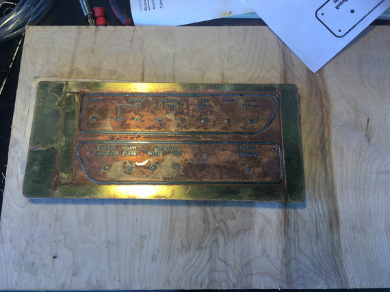
Pulled out
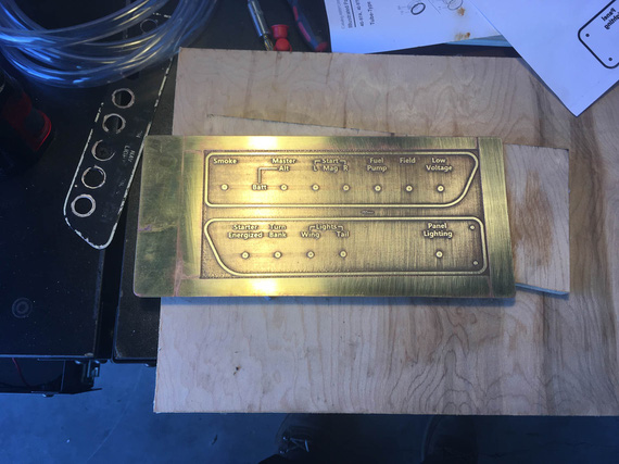
And cleaned up!
Nice! I liked it! The etched sections ended up a bit too thin, but workable still. I cleaned them up with maroon scotch brite by hand this time.
Next day, I cut them out, drilled the holes, and tried them on.
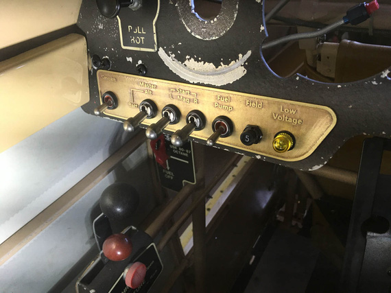
Left
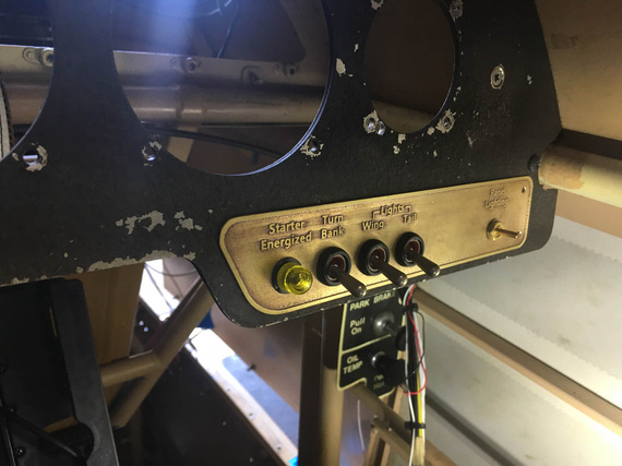
Right
I liked them! The only step left was the paint. But first,
Paint
I touched on the subject a bit already.
I was afraid of Rustoleum now, even learning that I messed it up myself with lacquer - it peeling off the base in sheets didn't give me confidence. Rustoleum has clear enamel; but my reasoning was that if it peeled off with primer, clear enamel without primer on relatively sharp edges of lettering will just come off almost immediately, given that my hands will always be around the switches when operating them.
I settled on epoxy. It made sense. Klass Kote had good reviews from RC guys, and folks reported it brushable.
I completely stripped my old sample with brass wire brush and acetone. Wire brush cleaned it out nicely and smoothed some roughness still left, so I wire brushed the new plates too. It helped, and seemingly worked better than the maroon pad! Noted.
And then, I set up in the kitchen.
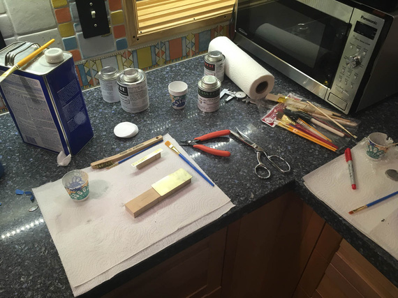
Set up for painting.
Klass Kote needs to be mixed, and reacted for at least 30 minutes prior to application. My plan (approved by Klass Kote) was to do base in black, then bake it after initial flash off for 30 minutes at about 100 degrees Celsius. That will cure it enough to make it sandable, after which I'd sand down the letters, and clear coat it. I won't need to bake the clear, 'cause I'm then done for the night, and it can take it's sweet time curing.
Klass Kote is really thick when mixed!
Trying it straight on my test coupons left horrible brush marks.
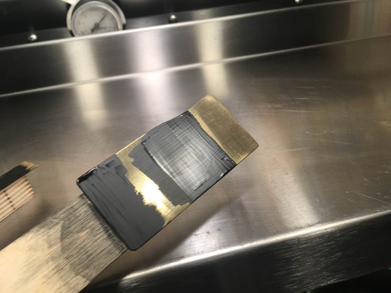
Straight Klass Kote black
I tried it on my test plate as well - just to play with the baking process.
Meanwhile, mixed up a new batch and wanted to try it reduced with a lot of reducer to see if that would make it flow better.
Nope. That left the same brush marks, but just watered down, if you will. Multiple coats just made it uglier.
Hmm... Meanwhile, I had a batch of clear mixed too, and tried to see how the clear would look over my test plate that was now baked and ready to be sanded down. Maybe, the brush marks would get better / a bit more hidden with extra brush marks of clear?
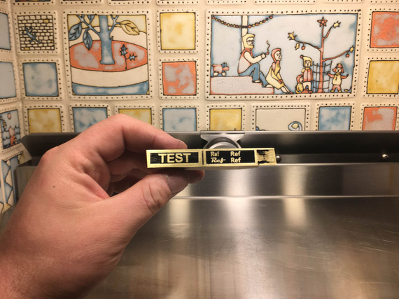
Test plate
Not bad, right? Well, you're not looking at it right.
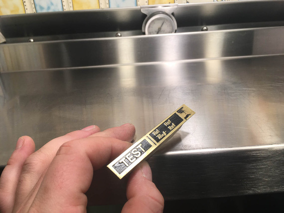
With light
See?
That's horrible.
Frustrated, I dumped my thinned batch of black into the tray I was using for garbage, and sat down thinking. My eye fell on a foam brush I had in the set of brushes I bought. I mindlessly picked it up, and started smudging the dumped paint around the tray.
It flowed! Very nicely!
I then remembered how much I hate brushes in general. I was never able to get anything remotely approaching good with brushes. When I built my kitchen cabs, I used cotton pads over foam brushes and achieved very smooth, mark-less results.
I think, this random act might've just worked!
I cleaned up my other, flat, coupon (the one that wasn't baked, so the epoxy would still come off with some wiping with the reducer).
I was now planning to mix the final batch of black I'd reduce. I'd try it on the coupon first, and then, if I liked the results, on the actual pieces...
...it went on smooth, but fish-eyed a bit. I thought that that was due to some crud on the coupon (I wasn't cleaning the coupon too good).
So, I put it on the actual plates.
It fisheyed! A lot of eyes flowed together, but some big ones stayed. I quickly dabbed them out with the corner of the brush with some paint on it - too late, damn it! It didn't flow out. The whole thing was also rough-ish... thinned paint was flowing around imperfections of the etched surface, as well as my dabs were messing with it, probably. There were also areas that had visible marks of me lifting the brush.
At this point, I should've stopped, dunked it into the reducer, washed the whole thing off, and called it a nite.
But, I was too focused on getting there.
I thought, I might be able to get a uniform "rough" look.
Solvent was flashing off, and paint was getting thicker.
More paint, but this time gently, not to rub old paint off. Then, dab-dabbidy-dab the foam in and out.
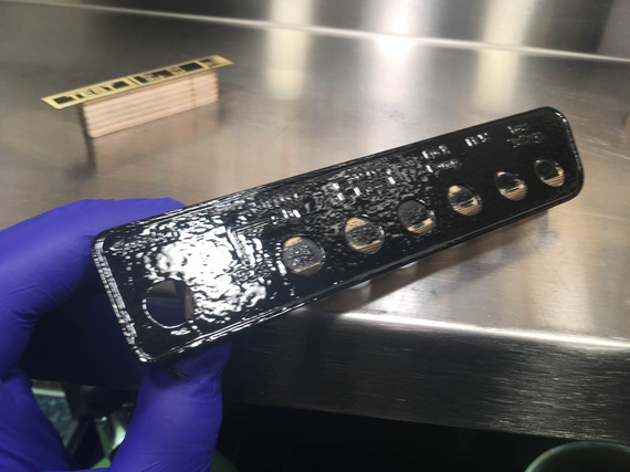
Rough look
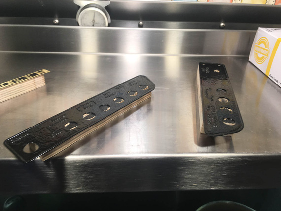
..on both
That looked acceptable, and I decided to let it flash off the solvent. Meanwhile, went to Walmart for more foam brushes (I only had two in the set).
Got back, mixed a batch of clear and left it off to react. It was looking good, with "rough look", and I was thinking I might just be able to pull it off.
After the paint stopped being tacky, put the whole thing into my oven.
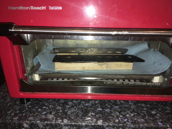
What's for lunch, ma?
Yep, that's my toaster, repurposed as epoxy bake oven, and calibrated at 100 degrees Celsius :).
I forgot about solvent pop.
See, when you have too thick a layer of paint (which I did, when doing my "rough look" pass), and the top of it skins off, some solvent might get trapped under it. What happens then is the trapped solvent tries to evaporate, and can't: pressure builds, and it "pops" the paint, making a tiny little pinhole.
So after 30 minutes, I pulled the plates out of the oven. Yep, I got the pop a-plenty. Some areas of paint that were especially thick got a ton of them.
I decided to stop then. Screw it. Rustoleum it is, as much as I hate the idea. This epoxy stuff is great (no, really, it is); but I need to spray it. So, I took a rag, wetted it with the solvent, and tried to rub the paint off.
Nope! It cured enough to no longer rub off with the reducer! Crap. Now, the only way to get it off is with Methylene Chloride stripper... :(
Oh well. What's the best second option for a frustrated guy who failed at a paintjob at around 2 in the morning? Stop? Go to bed? Strip and start anew?
Nope! I thought, "well, I had a batch of clear right here. I can see if I can rub out the worst uglies with something, and try to clear it to see if it'll hide the rest".
Admittedly, it did hide pretty neat.
I rubbed out the worst popped parts with maroon scotch brite, and sanded down the lettering.
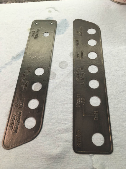
Left's not rubbed, right's rubbed
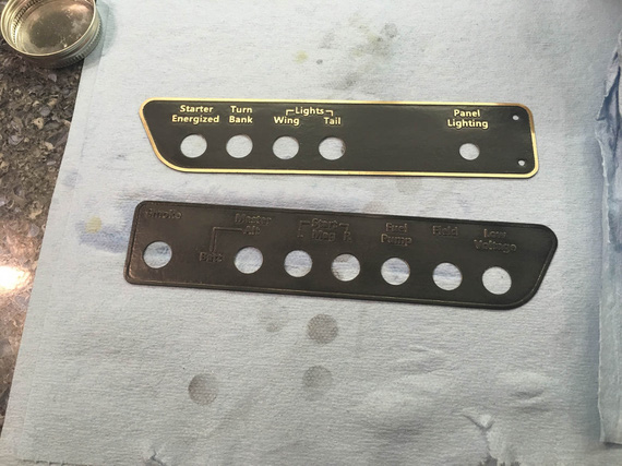
Bottom's rubbed, top's rubbed and sanded
And then, I clear coated them with two coats, cleaned up, and went to bed.
So, did they come out okay?
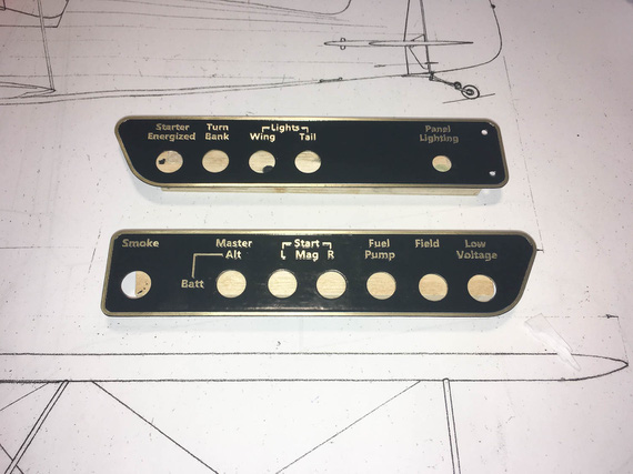
Finished
They look okay if looked at like that. I don't know. They're ugly, if looked at in the right light.
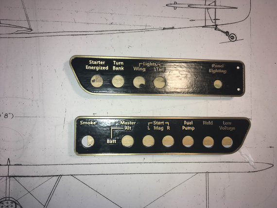
With the right light
On the other hand, it matches the "rough style" of the old school plates. I really don't know.
What I should've done from the get go is either used Rustoleum, or got myself an airbrush. With an airbrush, it would've worked much nicer.
Maybe, I will strip them and re-do the paint. Maybe not - that kind of light is unusual in a cockpit. Maybe I will file this under the "don't be an idiot / don't rush a paintjob / use the right tools" section, and keep them as a reminder - until I have to make another set.
I don't know. We'll see.
Meanwhile, the Chairman says, "Come Fly With Me!"
Good judgment comes from experience and experience comes from bad judgment.
© Copyright "79FT". All rights reserved. Feel free to cite, but link back to the pages cited.
This website only shows how I did things in my various projects. These pages are for information and personal entertainment only and not to be construed as the only way, or even the perceived correct way of doing things. You are responsible for your own safety and techniques.
