[79FT]: Building Things |
 |
Done
...but now, a new beginning - flying!
| On: | Jun 15, 2021 |
| In: | [Chickenhouse Charger] Electrical Rebuild |
| Time logged: | 38.6 |
| Tags: | 6781G, MA5 Charger, w&b, fwf |
Well, this was quite a hiatus. I was at a point where I needed my IA to look at everything, make sure I didn't screw up too badly, and start closing her back up.
That took quite a while, with Mr. S. being super extra busy, and my venture away from snowstorms of Texas to real snowstorms of Idaho.
But finally, we got together.
'Run the trim all the way forward,' - said S. 'Okay, now run it back. How does it feel'?
'A bit crunchy,' - I said. 'Yep. You gotta lube the jackscrews. And clean that rust off of tubes and paint over it, over there at AutoZone they can mix you up any color'.
Phew. The motor checked out, compressions were good, sounded all normal and all. Not a bad start!
I also had to weigh her, with all the changes that I made.
Paint
That turned to be quite a disaster. I did get rid of lots of corrosion, but painting tubes hunched over, or using some other way to get to the point I tried to paint was abysmal. I will admit to trying to spray, making a hell of a mess, and giving up on that very quickly. I'd have to mask literally everything - the kind of paint they gave me floated and didn't dry up anywhere near quick enough to be reasonable.
Ended up removing a couple tubes (happened to have been ruder pedal connecting rods) that I could remove and painting them outside - that was pleasant, compared to the rest of the affair.
Didn't even take a single picture.
Closing Up
Well. First of, instead of using nutplates, everywhere where the back side was deemed reachable, Remo decided to just leave a hole and put a regular nut on the finish screw that was deemed accessible from the back. Lots, and lots, of grief.
Just wing intersection fairings took 3 evenings to put on.
Then, I discovered that fabric was torn around one of the inspection plates, and it's couple nutplates were missing. I basically had two large holes in fabric.
Pondered this a bit, and made up this little monstrosity:
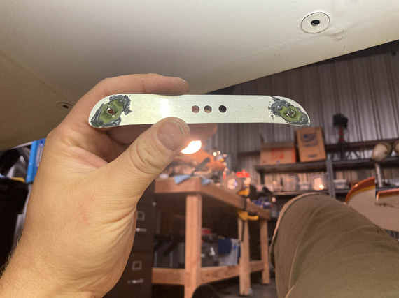
Backer plate
The idea is that this thing goes on the back, and fabric gets sandwiched between it and the inspection plate. I had to use #6 screws, and the only nutplates I had were for sheet metal screws. Well, that just adds to ugliness. And no, I didn't have riveting equipment to properly rivet them on - but JB-Weld works just as well; and is only there to prevent plates turning under torque anyway.
Here it is, this monster "nutplate", peeking thru the hole in the fabric.
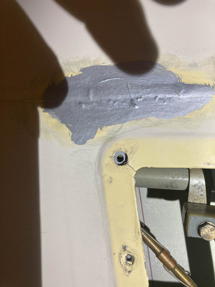
Peeking
Used 3M FireBlock to patch up all the holes in the firewall with gaps around them.
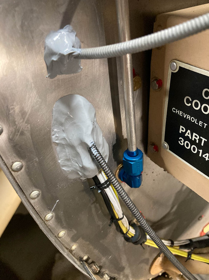
FireBlock
It's a fancy sealant, consistency of your usual RTV silicone. I shaped the "mounds" with my finger constantly wetted in mineral spirits - that prevented wet sealant from sticking to it, and allowed me to work it reasonably well.
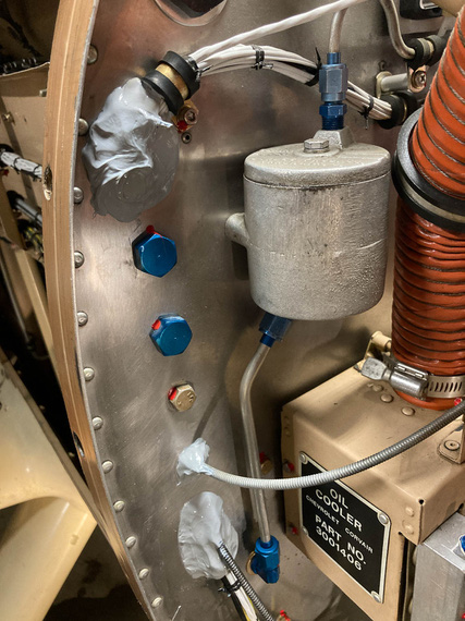
More FireBlock
Safety wired the prop. Momentous occasion!!!
I suck at safetying. I shouldn't, but I completely suck at it :(
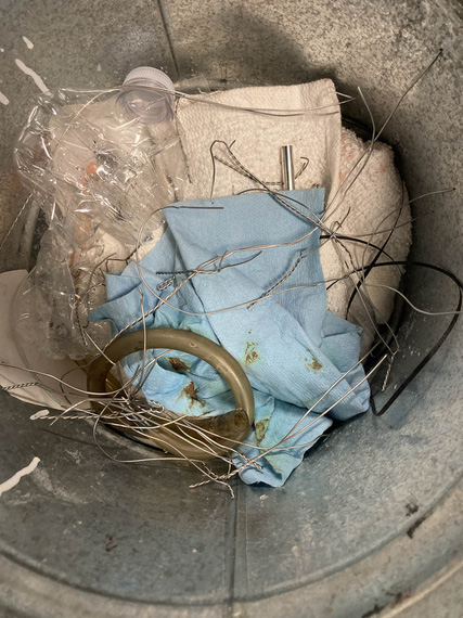
Many many attempts
Well, and then the rest of it. Plates, plates, plates. Oh, this guy made a home around one of my aileron hinges:
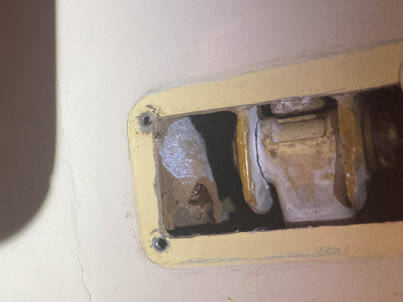
An un-invited guest made his house here
You do know stories of these guys bringing down large planes, yes?
... and more fairings, and more cussing about the nuts instead of nutplates.
But eventually, all of those were on, and the last thing left was...
Weight and Balance
This one was fun actually. Fun, and sketchy. Sketchy as ...
I had to raise the tail pretty high. Felt like about 4 feet high.
So it basically is a game of "ladders", with dynamics of Jenga blocks.
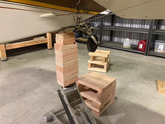
Up
You raise it as high as it'll go, stick something under the tail wheel, add an "extension" to the jack, raise it higher...
After the first "extension" on that car jack I quickly realized that was too sketchy, and switched to a bottle jack. That was a lot more uneventful, but went much slower (bottle jack has something like 10 inches extension, and needs a second "ladder" for itself as well).
Oh, all those boards are screwed together. It's not a high-stakes Jenga, after all :).
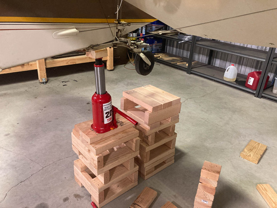
With bottle jack
Here's the final setup, on scales. Airplane level and with all the "flair" attached to it. Well, can you find the pieces not yet permanently attached; but at least in the right spots?
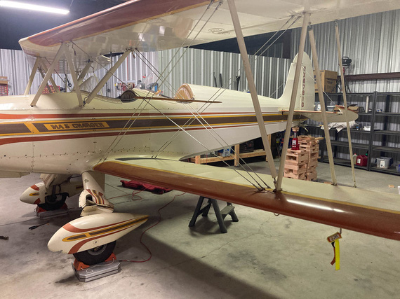
On scales
So how did we do?
I lost 11 pounds! Makes sense, too: with smaller and lighter alternator, much less (and much thinner - appropriate for amperage!), wires, removed mechanical engine instruments, etc etc etc. CG moved back just a hair, too: which indicates loss of weight closer to the front of the airplane. Again, makes sense!
"Georgetown Ground, Yellow FJ..."
And so, we were done. Anti-climactic, really. Felt that way at the very least. She was dry (had to be for weighing) - very conveniently, too, I managed to just burn off the last gas I had in her, so didn't need to drain anything. But I needed new gas - to, well, get gas - so that I had enough to taxi to the pumps.
Hmmm.
Called the tower, they were okay with the idea, so ahead I went.
Pulled up in my car to the movement area threshold with the gas can in the back.
"Georgetown Ground, Yellow FJ Cruiser, at Trinity, taxi to the pumps" "Yellow FJ, proceed on A-1" "Proceed on A-1, yellow FJ"
That was a first.
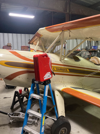
?!
That is not sketchy. No sir. Not at all. I decided to put gas in the wing tank, so that I would know exactly what my main tank capacity is - measured myself.
Came out to 26.1 gallons - with .1 non-useable that I drained, that was right on the mark.
And then, the next day, took Mr. M to the airport. We climbed in, donned our headsets on, taxied up to the pumps, filled her up, and went back and forth on the long taxiway a few times - so that I could remember my footwork and break in new brake linings , and he could just have some fun.
Felt good. Really good.
Fighter pilots make movies, attack pilots make history.
Up ↑
Baffle Seals
...are baffling!
| On: | Mar 13, 2021 |
| In: | [Chickenhouse Charger] Electrical Rebuild |
| Time logged: | 20.5 |
| Tags: | 6781G, MA5 Charger, FWF, baffles, engine |
One last thing identifiable as a "sub-project" left! Also, the most annoying thing probably.
Baffle seals.
The old ones were cruddy, petrified, and worn. In fact, baffles were what I was working on when I discovered that I needed to rebuild the electrical.
So I guess it made sense to finish where I started.
I pulled the old ones out of their bag, looked thru my notes of what goes where, and put them back up.
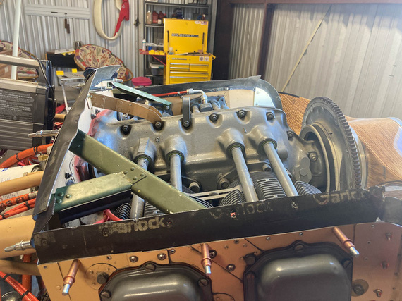
Old baffle seals back on
And then, duplicating and tweaking.
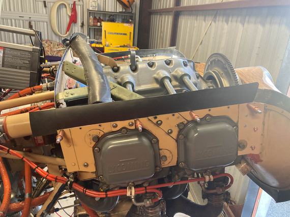
New seal fitting
Weirdness number one - or rather, unusualness? - was how Remo hooked up the nosebowl. On most airplanes (and on the plans as well!) the nosebowl is just held by the rest of the cowling.
On this Charger, Remo decided to hold it on four U-channels bent out of aluminum going from the firewall to the nosebowl. Those U-channels would also act as cowl stiffeners.
Here's one of them, on top of the engine baffle.
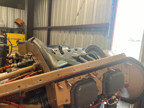
Hosebowl support C-channel
I even think I know why. He probably attached the nosebowl to the flywheel with some kind of a jig, lined everything up the way he liked, and made those.. stringers? I'll call them stringers. In place. That held the nosebowl, and he could build the rest of the cowling around them.
Problem?
Well, the two on the top have to go "thru" the "airbox" that's created between the motor and the top cowl, making two nice holes in it - and allowing air to escape thru them rather than be forced down thru the cylinders.
Here you are looking towards the firewall thru one of those hose.
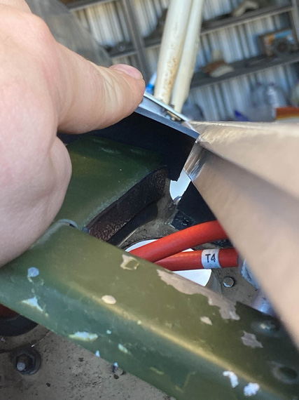
Hole
I pondered this for a while, asking Mr. D. if on his Eagle he built he had anything like that. He said no; his cowling was "normal". No "stringers". I thought about making some small strips and attaching them to the "stringers" to plug these holes. I thought about maybe filling them with RTV (making those stringers' removal a fun affair).
At the end, decided that for now, I am going to ignore it. There are much larger "takeoff" holes right there - for the oil cooler on one side, and for the fuel pump on the other. So, there.
The other problem was that instead of using standard 1/8" large-head pop rivets almost everyone uses to attach the seals, Remo decided to be "frugal" (weight savings?) and used 3/32" rivets on the back baffle. He used 1/8 rivets on the side baffles alright; but instead of using large-heads, he drilled the holes too close to the edge and used a "retaining strip" - basically, a narrow piece of aluminum on the "rubber side" that acted as one long washer.
That's all good, but of course they were old, torn to pieces due to vibration, and basically all broke up when I removed the old baffles.
I toyed with the idea of using large head rivets or emulating them with washers.
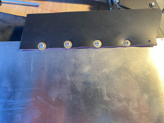
Large head rivets emulated with washers.
Talking to Mr. J.F., one of the IAs on the field, he seemed fine with that. Mr. D of that Eagle fame said it was a good idea too. Mr. J.F. said, "baffles are baffling", by which unwillingly contributed to the subtitle of this rant.
In the end, I ended up remaking the retaining strips.
Why?
Because the holes were too close to the edge. A larger diameter rivet or washer will "poke in" to the seal when it bends down, and quickly cut a slot in it. The seal will tear up, and.. well, that's the end of that seal.
So, the strips.
Using old ones as templates to replicate was out of the question - they were too beat up. So, the second best option? Make them in place.
First, the holes.
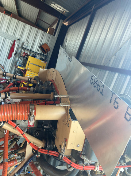
Drilling holes to match
Then, I would draw the edge onto the metal and take it off...
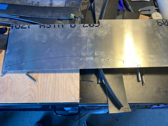
Top edge duplicated
... cut it, and put it back on to make sure the edges would match up
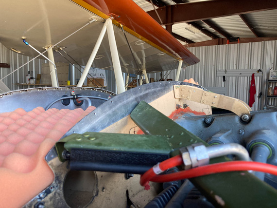
Test fit
The bottom edge would be duplicated off of the top edge using a compass, and - voila:
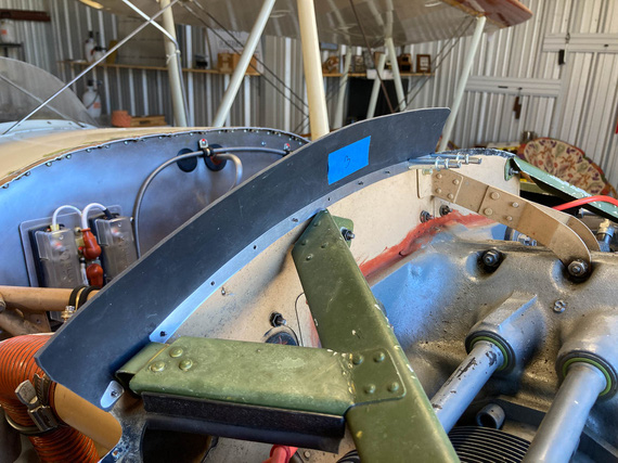
The new strip
The strip would be done.
And that, all around.
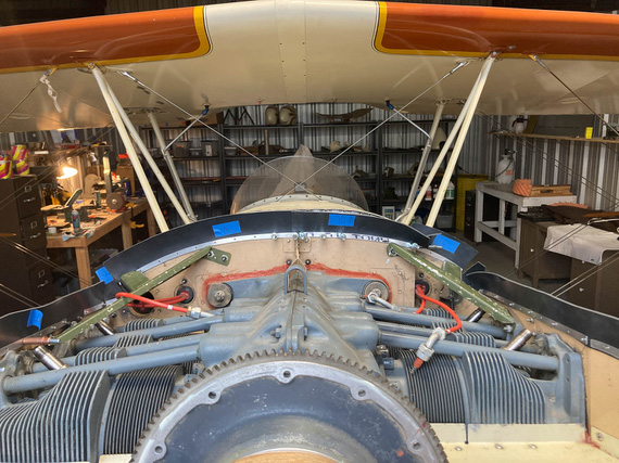
New retaining strips
Final test would be making sure it fit with the cowling - didn't pinch anything anywhere...
Except that...
Funny story. The top piece of the cowling was standing upright (grave mistake!) on the top of a shelf in the back of the hangar. For a year, or probably even more.
And then, one day, it did catch a particular gust of wind that so rudely entered the premises, couldn't stand the offense, and fell down.
WHACK! I heard.
First thought: "Please, not on the airplane!". No, it didn't fall on the airplane.
But it did mess itself up.
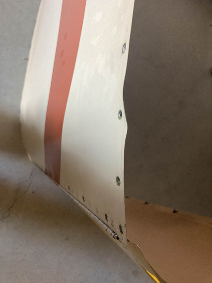
Bent cowl
So I guess I learned my lesson at not to steep a price.
Mr. M, the same Mr. M that welded my exhaust tailpipe back on made quick work of it with his very fancy shrinker.
The cowling went on, and I confirmed that everything would fit - because next, the seals would be riveted permanently.
Then, Mr. M decided to join me. He'd pull a Cleco, and I'd pop a rivet...
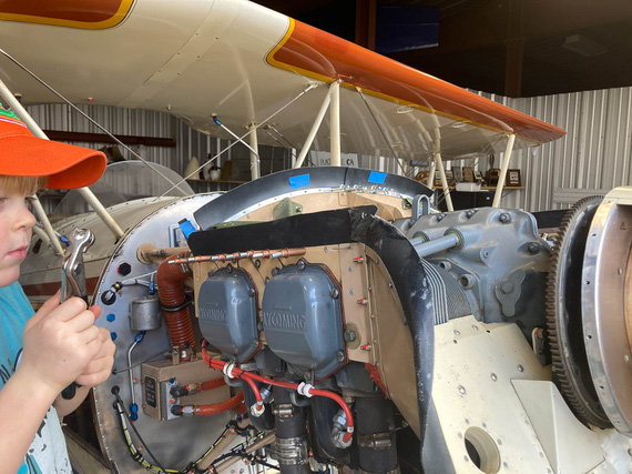
Riveting
...and, we were all done!
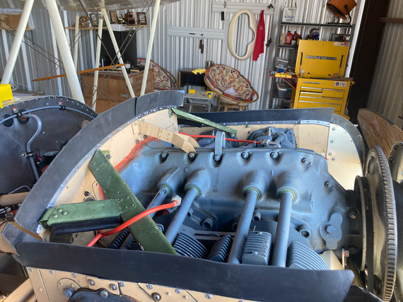
Done
Some final passes with RTV to patch up some holes between the metal and the motor, and I call this good to go.
CAUTION: Aviation may be hazardous to your wealth.
Up ↑
Oil Cooler and Hoses
...mainly, fiddling
| On: | Mar 12, 2021 |
| In: | [Chickenhouse Charger] Electrical Rebuild |
| Time logged: | 6.9 |
| Tags: | 6781G, MA5 Charger, FWF, engine |
After my first run, one of the things that I quickly discovered was that the oil cooler hoses leaked from behind the hose ends.
Of course; the only two engine hoses I have not replaced must leak. That's just Murphy's law.
And of course, since I was messing with it, I had to tweak it to my liking, and I am glad I did.
I wanted to replace these two fittings.
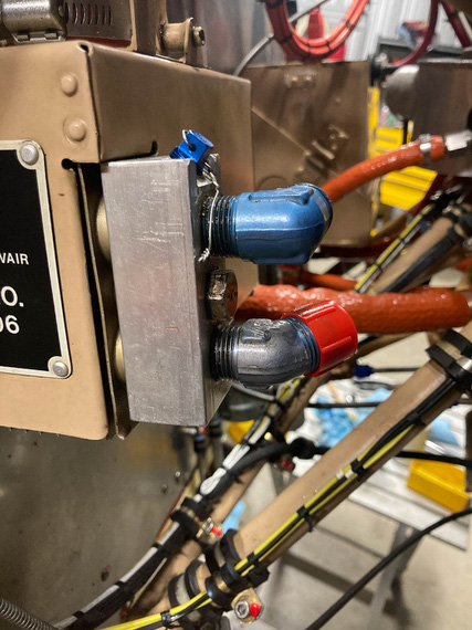
Oil cooler inlet and outlet
They were both aluminum, and one of them was scratched - I didn't like that; and I like steel fittings on thinks like this. Plus, the hoses are long and heavy. I'd feel better.
So the oil cooler had to come off, so that I could take off that aluminum.. "manifold"? block off of it, stick it into a vice, and undo the fittings.
Ha!
To do that, I had to remove the shroud... attached with screws, some of which I very conveniently blocked access to with my new brake line I relocated.
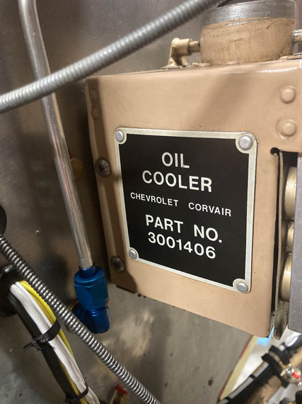
Oil cooler fastners: blocked off
Well, shucks.
Custom ground and shortened Phillips bit was in order, and that helped me undo the screws.
Then, the manifold block came off.
You can see in the first picture above that the block is held to the cooler with a large bolt - going thru the cooler, with it's nut on the other side. There must be some kind of sealing between the cooler and the block, right?
Well,
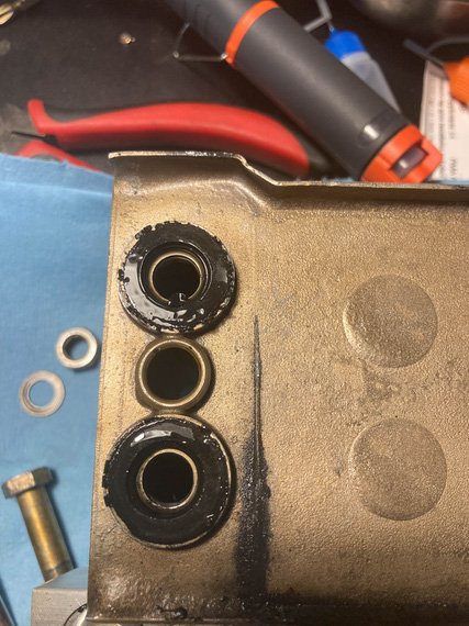
Seals that were
Yeah.
Now, this is a Corvair cooler - and I learned that they interface to the motor on the original car using these rubber donuts - but these seals looked nothing like Corvair's. They instead were these weird step-washers - one side interfacing to the surface of the oil cooler, and the other - to the grooves machined in the manifold block
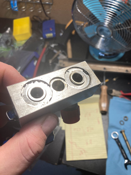
Seals interface on the manifold
What probably happened is Remo, or whomever installed this cooler, had some seals lying around, machined the block to fit them, and called it a day.
Trying to find these yielded no results - but I got an idea.
O-Rings. If I found the o-rings of just the right size and thickness such that they would be just a bit bigger than the distance between sealing surfaces, screwing the manifold block back to the oil cooler would squish them tight, and they will hold the pressure just fine.
Here's the idea.
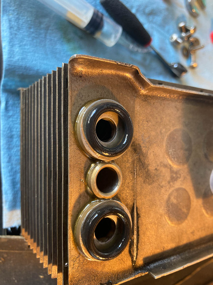
O-rings as seals
These were a bit too big, but the next size smaller worked out. I wrote it down for the future (but I do have a bag of like a hundred of them, too). Made sure the temp spec on them was in the range, too, and that they were okay to use with engine oil.
Meanwhile, also cleaned up all the ragged edges, cleaned up the threads inside the manifold, got a couple of new steel fittings, and a couple hoses from Tim at TS FlightLines.
The rest of putting the thing together was a non-event. Oh, and I ended up using hex-head screws for the side where access was blocked off by that brake line - so that they could be tightened with an open end wrench.
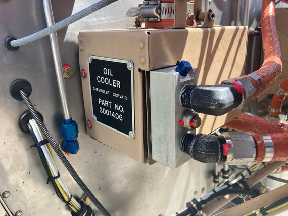
All done
Test run, no leaks found.
Jet noise: The sound of freedom.
Up ↑
Chips and Dings
...Cleetus-Style
| On: | Mar 11, 2021 |
| In: | [Chickenhouse Charger] Electrical Rebuild |
| Time logged: | 22.5 |
| Tags: | 6781G, MA5 Charger, paint, fabric, polyfiber |
The end in sight; fixing up all the chipping off paint was one of the remaining little things to fix on the Charger before she could take back to the air.
Regardless of history, I knew that she was painted with Polyfiber and Polytone (MEK test proved that).
Back in 2019, when I just got her, this was one of the things I have discussed with a couple of fabric folks, and a few folks from Polyfiber during Oshkosh. With variations, this approach is what seems to be the common theme unless one wants to do a drastic restore - either rejuvenate, or recover.
But first, she needed a bath after almost 2 years in the hangar :).
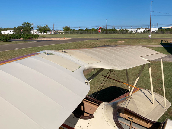
One wing donw, one to go
What a difference, eh?
I had a bunch of areas like this:
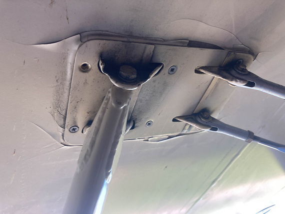
Chips and cracks
Large and small, mostly in the prop wash area where things drum the most.
The approach is not much to talk about. I called it Cleetus-style: a perfect redneck fix for chips in fabric that's purely functional and ugly as hell, and even has the perfect color of duct-tape.
First, I would chip out all the flaking paint, while not being too aggressive: one of the guys I talked to said that if you get to excited with chipping and peeling, you can peel the whole plane if the coatings are starting to lift.
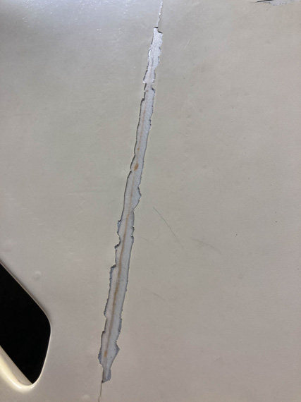
Chipped
Then, I would take a rag wet with MEK, and work those edges of remaining paint to melt and blend them in, creating somewhat of a "slope"...
Feathered edges
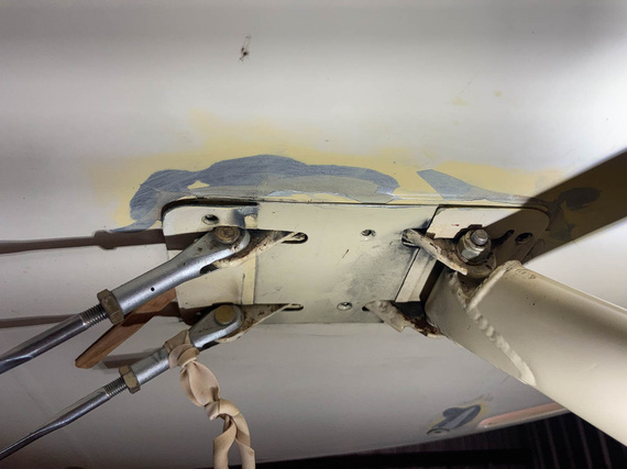
And then, I would layer silver (Polyspray) on top of pink (Polybrush) until it was just the perfect level of ugly, and I would feel that I have enough Polyspray to prevent UV attacking the fabric... Doing a 60 watt bulb test to see if any light's coming thru was not really adequately possible for these cracks really, and I opted for layering silver thick enough to be sure I'll have a sufficient amount.
The result?
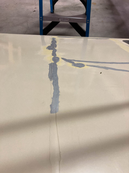
Perfect ugliness
Perfect ugliness! "You're giving your plane leprosy", remarked my old buddy Jimmy C., accidentally bumping into me in my hangar when he was at the airport. "Yep", I said. Indeed.
Interestingly enough, roughly at the same time someone with a similar problem was soliciting advice on the Biplane Forum. I offered making him a short video about my process, and it turned out to be a much better illustration than what I got above.
The probability of survival is equal to the angle of arrival.
Up ↑
Exhaust Clamps
...shucks!
| On: | Oct 16, 2020 |
| In: | [Chickenhouse Charger] Electrical Rebuild |
| Time logged: | 9.0 |
| Tags: | 6781G, MA5 Charger, FWF, engine, exhaust |
About a week after engine start (yep, I took a break), back at the airport, and looking over the motor again, trying to figure out what the hell was that electrical type smell...
One theory formed...
You see, I hung the exhaust with copious amounts of anti-seize. I do have either a Grumman or a Cessna style exhaust, with 4 "stubs" (aka risers) coming off of the motor, and a "spider" looking setup hooking to them, joining all cylinders into a muffler under the front of the motor.
Risers go inside the main exhaust, and are held by clamps, engaging "beads" on the pipes.
So I thought, I'd hang the whole thing "loosely", so that individual cylinders will move, and use high-temp anti-seize to make sure it, well, doesn't seize up.
The working theory was that that anti-seize was "cooking" and produced a smell. I saw a lot of it blown out from around the clamps.
Another working theory was that maybe there was an insect or few stuck around the baffles or cylinders somewhere. There was one big wasp in there that I saw after the engine start - and smoldering insect carcasses sometimes smells just like burning wiring.
I know that last bit, because I spent insane amount of time, and got aggravated to no end, when I got this weird electrical burning smell in my old house. I was convinced I hit a wire when hanging some stuff to the studs just a few days before, and I literally drilled holes along every place where I hung things with a hole saw to make sure there were no wires.
There was one, but it wasn't pinched or damaged.
And all that was finally traced to a roach that died inside my air conditioner heat exchanger, right on a heat strip - heating season just started, the roach was dead and smoldering, and the AC was blowing that lovely smell all over the house. I later read a lot of fire department stories about similar situations of people freaking out and thinking their houses were on fire.
At any rate. My theory was either the wasp, or the anti-seize.
And my anti-seize blew out of the joints real well (ha!) - sooo.. I guess, the loose hanging exhaust idea was a no go.
And, by the way.
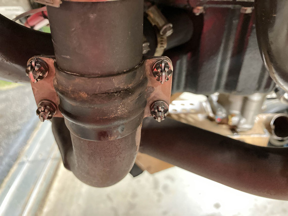
Crack!
Damn.
So the exhaust was taken off, again.
After quite some researching, here's what I found.
I had 1 3/4 risers.
Those clamps are ubiquitous Cessna clamps. Part number irrelevant - because...
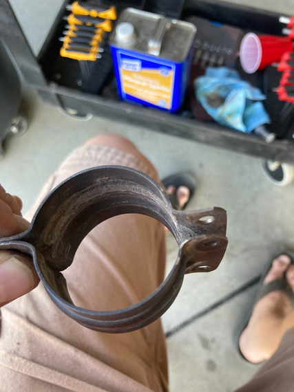
Cessna clamps
Grumman also has 1 3/4 risers.
I was convinced I had a Grumman exhaust, because hey, what'd you take: a Cessna or a Grumman? :)
Those clamps are impossible to make to not leak. Forums confirmed by the way. Mr. John F. confirmed, too. Just think about them for a second - they will leak.
Grumman clamps are a bit different - they have this "liner" that is supposed to act as a gasket.
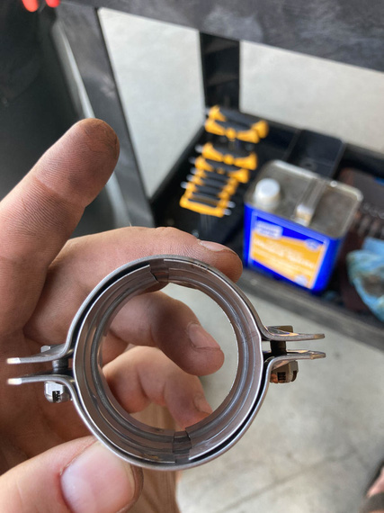
Grumman clamp
Yep, you guessed. I went Grumman. I don't have any Cessna friends. I have a ton of Grumman friends. You know where my heart lies.
Grumman book does not state anything about hanging the exhaust "loosely". It states to use Walker AcoustiSeal <part number here that doesn't exist anymore> (of course).
Mr. David Fletcher of Fletchair by the way confirmed that the exhaust needs to be tightened down, and that it's not a usual problem with it cracking due to differential movement of cylinder heads. Or rather, of course it will crack. But not all the time - it's perfectly fine.
We spent quite some time with Ben, figuring out the clamps (I was initially reluctant to fully close them because of the liner deforming too much), and AcoustiSeal. He helped find a catalogue AcoustiSeal with a different part number - 35959 - that is definitely within the temp range. I decided to use that instead of anti-seize. Researching a bit, it seems to "burn up" and "ash out" forming a fluffy, powdery type seal.
Cleaned every pipe, put on the new clamps with AcoustiSeal, and tightened them down. That was bad. Really bad. Torque was definitely excessive to close them, but I had to close them. It's obvious why, too - the OD of the pipe is 1 3/4; the ID of the clamp is 1 3/4, but the thickness of the steel liner is about 1/64 - so yeah. And my pipes aren't perfectly round, or smooth, either.
But they did close, and they did fine in the end.
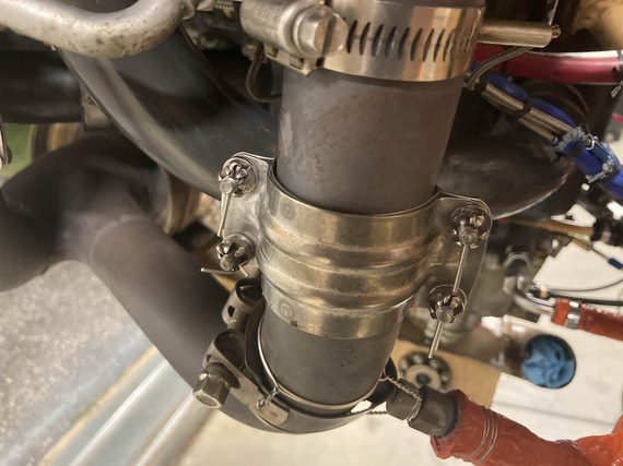
New clamps
I decided to try them. Worst case, I'd go back to Cessna style.
Also, cleaned up around the smoke oil injectors, and put AcoustiSeal there too. You can see one on the picture above. Re-safetied them a bit better too - the idea Glenn had was that if the main worm clamp failed, the safety wire will at least hold them in place.
And then, the other question came up that we spent quite a bit of time arguing over with Ben.
What's the torque on the Lycoming exhaust nuts?
It's not listed. Stud driving torque is listed. It's listed for vertical and geared motors in relevant sections of SSP-1776 at 160-180. Grumman book lists them at .. 110-140 if I recall correctly. The "by the book" application of "default torque unless otherwise noted" section of the "Direct Drive Engine" part would put it at 204-228. All inch pounds. So the range, depending on the source, would be 110-228 - a 100% difference. !!!
A lot of folks on the internet use the "default" - 204-228. A few were told to do so by Lycoming. When I torqued them, it felt... somewhat excessive, given that there's a gasket in play there too. There's no straight answer, really.
I settled on 180. Why? Grumman's book assumes "beaded" - not "no-blow" - gaskets. 180 is much closer to 204. 12% difference - within margin of error of a crappy typical torque wrench. And if mine is reading "high", I'll still be in the range listed for geared and vertical motors - which have the same cylinders as far as I know.
Yep, convoluted.
Anyway, second run yielded a very different smell - this time, of the regular "burning oil" sensation (which is typical for a motor that slowly weeps oil and throws it everywhere when shaking - that's the built in feature of spray lubrication and corrosion protection of your motor compartment! What? You weren't aware of that?!).
Much better. No blowouts of sealant anymore. No exhaust leaks I could discern.
... and, an oily fitting that I thought was oily after the first run because we used it to pour oil into the oil pump - but no, I confirmed a hose leak around the fitting of the only two hoses (oil cooler supply and return) I did not change.
Le sigh.
"Listen up gentlemen, or something's gonna happen that none of us wants to see. Besides that, you're (tickin') me off!"
-ORD ATC
Up ↑
Motor Start
...:)
| On: | Oct 15, 2020 |
| In: | [Chickenhouse Charger] Electrical Rebuild |
| Time logged: | 23.0 |
| Tags: | 6781G, MA5 Charger, FWF, electrical, engine, exhaust, alternator, fabrication |
And so, we're onto the race to the first motor run. I am writing this about a month later - according to the log, the motor was started up September 19, 2020.
But first...
Upfront
Finish mounting the starter was no problem: clean up the threads, clean up the studs, torque, done. Then, the alternator.
Belt tensioning... too annoying by hand, but it took me a while to stop trying and become sensible.
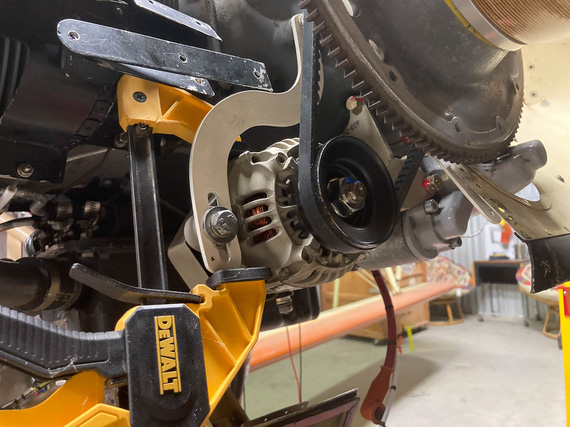
Belt Tensioning
You gotta safety two bolts over there, and I decided to make it nice: for the bottom (pivot) bolt, drilled a tiny hole in the bracket lower than where the alternator would be, and for the top bolt attaching the bracket to the motor... hmmm...
Somewhere on VansAirforce someone used a cherry rivet as a "hookup" point for the safety wire. I thought to one-up that, and use a short #8 screw - drilling it's head.
Frankly, I didn't think it'd work out.
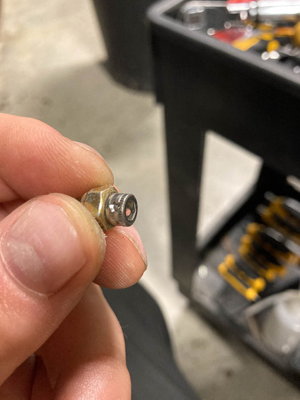
Drilled cap head
...but as you can see, it did.
So then, to the hole in the bracket. I needed a #8-32 tap.
Side, fun, story: quite a while ago I ended up bidding in a machine shop liquidation auction. Got quite a few nice things, including a very heavy duty bandsaw - and, accidentally, a massive cabinet full of tooling. Anything you could imagine: inserts, drills, taps, slitting saws, you name it. In all shapes and sizes. When we moved the cabinet, we emptied it into about 10 boxes, so ... I did have a #8-32 tap. In fact, probably about 20 of them. Question was, which one of the boxes were they in.
... apparently, in the one on the top. Hmm. This kind of luck is unusual.
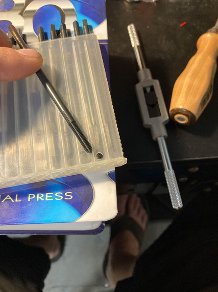
Tap
Look at it carefully. Does it look like a regular tap we are all used to?
Didn't to me either.
So to researching we went.
Aha! "Threadforming" tap. AKA "Cold Rolling". So that's how they're done. Rolled threads are formed into the metal rather than cut; giving them superior strength. Basically, the tap shapes the metal, displacing it in the valleys and raising peaks.
Company that made these taps was advertising them for CNC milling. Well, what's a human if not a bio-CNC machine?!
Okay, problem number 2. I was pretty sure normal tap and drill chart values for hole diameters won't work; making too small a hole. Hmm...
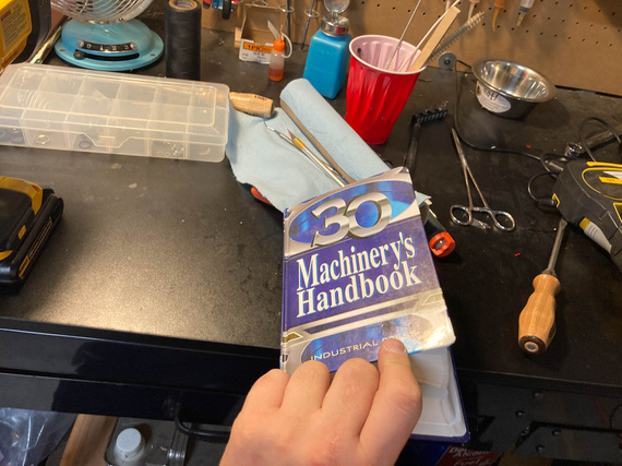
The Bible
Aha! "Ideal Theoretical Hole", and closest drill available charts are just what's needed.
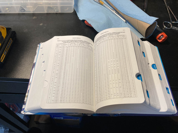
The Word
And with that, the affair was a non-event.
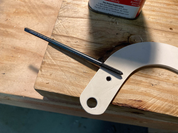
The Hole
Actually safetying was annoying - I had to try twice, because I had to use a hand-twister and you had to get the length just right.
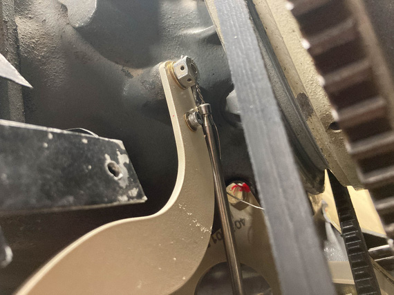
Hand Twister
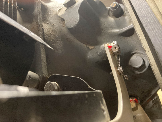
Safetied!
Airbox
That thing needed to be put back on, and carb final torqued with a new gasket. Cleaned it all up inside as much as I could, and had to cut a couple of special gaskets that I can't for the love of me figure out where to get (carb's base is different size from the top - and this is an "airframe" problem - read, "no standard part from Marvel or Lycoming I could find reasonably"). No problem. Used the same material Lycoming used for their gaskets, ordered from McMaster, and made me a couple.
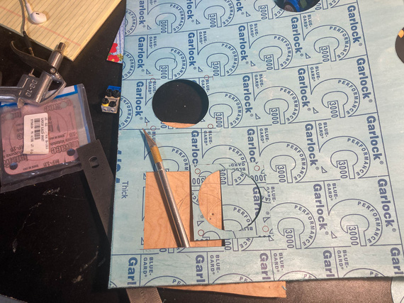
Cutting gaskets
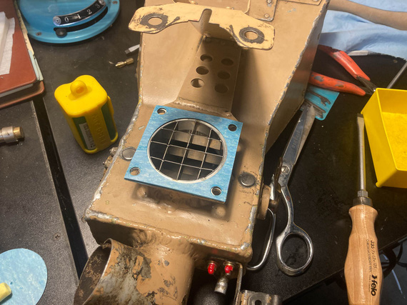
Where they go
Perceptive will see the "airflow straightener". Glenn had it on when he put on the Rotec TBI, and in the times of my research of TBIs, I have discovered that some folks claimed they helped on carbureted motors as well. Well, it definitely won't hurt - aside from my having to do two gaskets instead of one. No biggie.
Carb
One interesting thing that happened. I had to drain the carb bowl of all the preservative oil, and flush it, so I took off the plug, drained it, and started putting it back in. Plug's an NPT thread with torque listed by Lycoming in SSP-1776 at 144 inch pounds.
Hmmm.. I noticed it was going in way deeper than it was in before, and way "harder" than when I took it out.
Hmmm.. Well, it's Lycoming, they know what the hell they're talking about. So in it went, at 144 inch/lbs.
But this bugged me. I think some other day I pulled out the Marvel's manual. 25-30 inch/lbs?! WHAT?!
Back to Lycoming. 144. Marvel (the makers of the carb)? 25-30. Damn it. Forums? Nothing interesting.
I finally figured it out. In SSP-1776, in the table for special torques, Lycoming lists the plug to have 3/4 pipe threads. Mine were 1/8 NPT. Lycoming's torque for those is 40-44 inch/lbs. Still higher than Marvel, but much closer now.
So, I undid the plug, that cut a bit of the tapered thread "deeper", of course. And put it back in, with the right torque this time.
Other Stuff
And then, minor stuff here and there. Cleaned and prepped spark plugs. Put the exhaust back on. Tightened things that had to be tightened. Charged batteries. Tied up everything hanging loose. Gave the plane a good look all over.
We were ready for the final day. There were a number of things I needed two sets of hands for, and I had just the man lined up.
Day X - or, September 19, to be Precise.
My buddy Mr. N. agreed to help, and be my observer and fireman (just in case). Mr. M. was extremely inquisitive about how we're gonna be putting out a burning airplane, and I had to explain a number of times that the goal of an exercise of starting a motor that's been idle for a year is not to have it go ablaze, and having a fire watch nearby is a part of prudence, not expectations. He seemed to have been disappointed. I would be too, if I was 5.
So, on a nice Saturday, we went to the airport.
First, drained all the pickling oil. Took off the prop (because we'd have to spin the motor to pressurize the oil lines). Put the fuel pump back on. Tightened all new fuel lines, and leak checked them. Mr. M. used my fancy "button with alligator clips" to turn it on. Put new oil in, primed the oil cooler and pump (and this is fun in this airplane, because there's no oil filler neck on the motor). Checked control cable travel, and final cotter pinned them. Checked brakes again (though we bled them when I finished fixing them up).
Then, came the pressurization, and purging of oil lines, time. Mr. M insisted that he wants to "press the button" - which would put +12V onto the starter contactor; bypassing my normal starting circuit (latter would make the left mag hot, and I didn't want that).
I told him to press the button and hold it and not let go till I told him to.
Now, starters with a motor with removed spark plugs are fast, loud, and annoyingly sounding. Mr. M. pressed the button. Jumped a bit. Grimaced a bit. He clearly didn't expect it. I didn't see it, Nick told me afterwards - I was watching the oil line. I yelled "Stop" when I saw the oil come out, and looked at Mr. M - who, at that point, was shaking and at the point of breaking down in tears. But! He didn't let go of the damn button. Man.
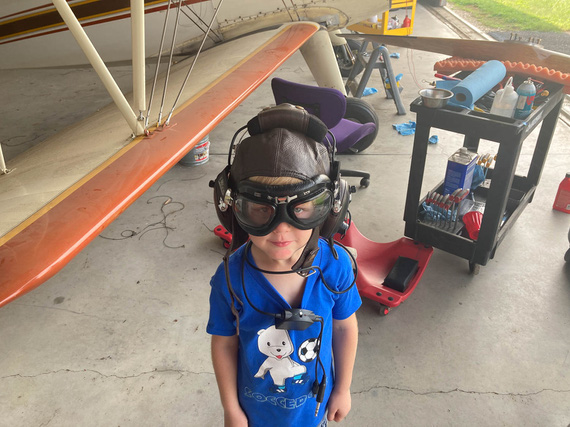
Mr. M
And that was that. Plugs went in, and we were ready, but broke for lunch, first. Mr M deserved his hot dog.
... back from lunch. Plane out. Wheels chocked. Brakes tested. Fire watch ready and instructed.
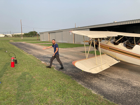
Final prep
... damn, that old Concord battery removed from the Cheetah years ago is weak and barely pulling thru.
... second try: no primer, so I have to pump the throttle a bit.
... she's alive!!!!!
I let the temps go up just a bit, and called N. He confirmed everything seemed to have been fine. We shut down, and went over every fluid fitting. All good.
Started her back up - I wanted to warm the oil to a reasonable temp and let her circulate for a bit, maybe 30 minutes - to get the juice flowing again.
On the second run, I revved her harder, and smelled something. Smelled like... burnt wiring? N. went around the engine, all wires, and everything he could see or think was close to being to a hot surface, or an electrical doodad. No signs of trouble.
We decided to proceed.
She ran just fine. I think we ran for about a total of 30 minutes. Shut her down, dragged her in. Went over the wires again - all of them. Nothing, all clean. There were no bad indications on any of the electrical instrumentation, either. So at that time, we left that as a mystery to be solved.
... and with that, we went home. We were tired.
Flying is better than walking. Walking is better than running. Running is better than crawling. All of these however, are better than extraction by a Med-Evac helicopter, even if this is technically a form of flying.
Up ↑
Wiring - Pt III
...part three: done!
| On: | Sep 07, 2020 |
| In: | [Chickenhouse Charger] Electrical Rebuild |
| Time logged: | 16.6 |
| Tags: | 6781G, MA5 Charger, electrical, panel, instruments |
... and the only bit of wiring left was the gauges at the panel.
It was not interesting in any way - mostly, lots of tying in awkward position.
A lot of stuff had to be done thru the front hole's headrest, while standing on a wing, and trying not to get "tangled" in the flying and landing wires.
Oh well.
I realized this was another mistake. Since all the gauge wires started at their transducers or sensors (amps, fuel and oil pressures, oil temp, and the like), I ran them "backwards" as one piece, and was planning to put on the corresponding D-Sub connectors in place.
What I didn't realize was how much pain it will be if I had to work in close quarters. And unfortunately, the 3-in-1 gauge - with the fattest of the connectors - required that.
What I should've done was cut the transducer and sensor's wires and made "whips" for them with connectors while on the bench. Then, I should've spliced them somewhere on the side of the airplane - yes, I'd have to do a lot of soldering, but that would've been better than what I ended up having to do...
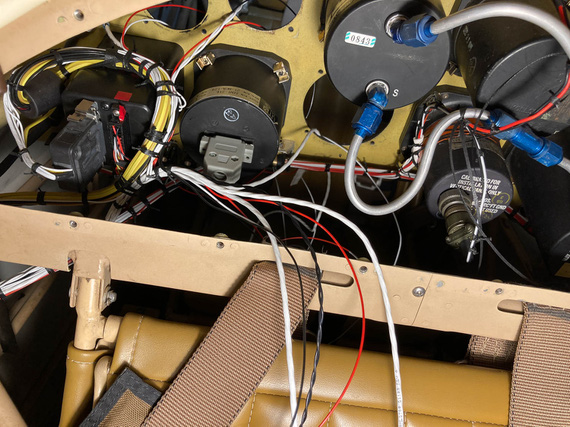
Instrument wires - and the back side of 3-in-1
You can see the DB-15 connector there - that's the 3-in-1. Sticking the wires thru the instrument hole, doing all the stripping and crimping from the panel side while sitting in the cockpit, and then tying the extra length up... maybe was possible, but seemed to me like it would be too much extra, producing ugliness and possibly rubbing on the structure nearby, so I decided to make that connector as close to the actual gauge as I could...
I tried it on the bench first, figuring out where I would put heatshrink, how much of the length is necessary for the connector, and the like.
Another interesting tidbit was that one of the connections had to feed two transducers off of the same one pin. Both wires were 22GA and I couldn't put them into the pin no matter how I tried - too much wire for one D-SUB pin's barrel. I'll show you the solution I used for that.
So, I bunched up the wires, put a round of heatshrink on, and prepped those power wires.
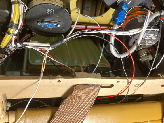
3-in-1 bundle
I bent the two power wires for transducers backwards "out" of the connector, and pigtailed a single 20ga wire to them. That looped back into the connector and hooked up to the pin.
Then, I set myself up on the wing, slouching over the front hole's combing, took my stripper, and stripped a wire... bam! 2/3ds of the strands came off...
What the..?!
I think the stripper pinched the wire when closing on it, and since I was so much out of position - practically upside down - I didn't notice...
And since I effectively just destroyed ~1/2 inch of the wire, and the wires were cut short....
I lucked out. The wire I was stripping was a standalone ground wire. Moreover, I had two more tails coming from the same source - for the other two gauges, and the unintentionally shortened tail I just made was just the right length for another gauge.
Phew. Only having to cut two knots, I re-routed the shortened wire to the other gauge, and that gauge's wire to the 3-in-1 bundle.
Tested the stripper multiple times. Yes, I think I just missed the right hole.
Making dead sure I was on this time, I tried again - phew. All worked out.
Slowly, everything got crimped.
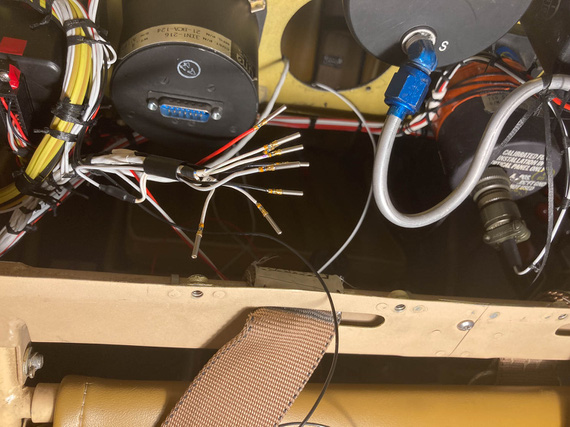
3-in-1 gauge pins
You can also see that "power loop" in the above picture.
Then, I installed the pins in the housing, and checked the 3-in-1 out. Used a plumber's gauge to pressurize pressure transducers with some appropriate amount of air and made sure the correct arrow went up on the 3-in-1, and by the right amount.
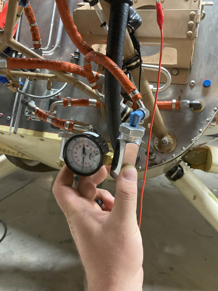
Testing pressure transducers
The other three gauges were much easier - because they were further from the 3-in-1 and tie point, for each of them I could trim and crimp the wires from the cockpit side. I had some fun times with the housing of the tach connector - a DB-9... UMA shipped me a weird sheet metal shell for it I've never seen that I think needs a special crimper to install, so I ended up replacing it with a regular cheapo plastic after spending what feels like a few hours trying to find out what the hell that shell was... Failed at that.
At any rate.
The final result? Well..
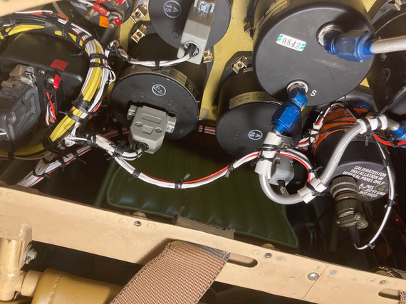
Beind the panel: done.
And with that, the re-wiring of the Charger was...
Complete!!!
"Leave five on the glide, have a nice ride, tower inside, twenty-six nine .... see ya!"
-ORD ATC
Up ↑
Wiring - Pt II
...part two
| On: | Sep 06, 2020 |
| In: | [Chickenhouse Charger] Electrical Rebuild |
| Time logged: | 18.21 |
| Tags: | 6781G, MA5 Charger, electrical, soldering, fwf, magnetoes, p-lead |
Well, we're continuing happily with wiring over here :).
Wingtips
SkyBeacon and SkySensor were to replace the existing nav lights. Yes, I know, SkySensor is probably a gimmick. But what the hell.
Remo ran nav light wires in a -4 tubing along the front wing spar, using it as kind of a "conduit", exiting the wires around the wingtip, and just soldering them to the nav lights he used. Wires were ~3 ft too long, which is a fine "service whip", but they were just laying on top of the inside of the fabric of the wingtip. There are no access holes on the wingtip, so no way to get in to tie them up.
Oh well. We work with what we have.
I was going to shorten the wires, and because the lights are on the top wing, I didn't want to solder them - I'd be doing it off of a ladder, very near if not on the wing's fabric... lots of things to go wrong.
The other thing I didn't want to happen was to have the connection points between the light's wire pigtails and wires in the wings to "rattle around" the wingtip (with no way of tying them down).
So I had this brilliant idea. The pic is post-realizing the idea was a mistake, with HST cut off....

SkySensor, and cut off HST
The lights had this plastic tube coming out thru which the wires were routed. I would shorten the pigtails as much as I could (like on the picture basically), hook'em up to the wing wires with barrel crimps, and put a long piece of my favorite glue-lined SCL tubing over them - with it glueing itself to the plastic tube and to the wires, creating one rigid "tube" coming off of the light...
Boy was that a mistake.
The tubing glued itself to the wires alright - but not to the plastic tube. So the whole thing created a rattly "lever" that would pull the wires thru that tube when vibrated - loading the soldered joints on the PCB of the SkySensor.
Not Good At All.
So that idea had to go to trash, and I had to cut the heatshrink off, carefully, with all the glue, without damaging the wires...
And ended up having to do exactly what I was trying to avoid - having rattling connections between the wing wires and the light, and to solder them. Why solder? Well, because the barrel crimps are heavy, relatively speaking, and I didn't want those heavy "bumps" bouncing around inside the wingtip, even with HST around them.
So, solder.
From the ladder, on top of the wing, covered in fabric.
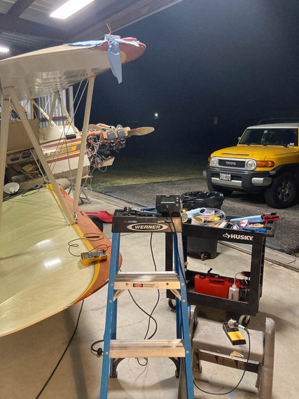
Soldering setup
You can see the heating station on top of the ladder, and the light ready on some layer of paper towels on top of the wings.
As usual, I used the Nuckolls Splice.
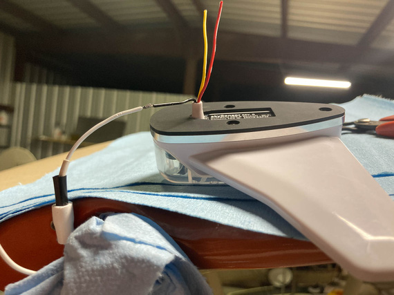
Prepped for soldering
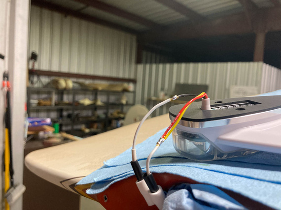
All soldered
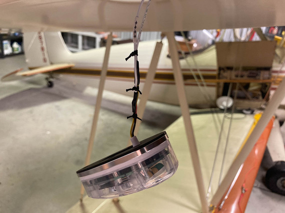
HST, and ties
The other side got the same treatment, and...
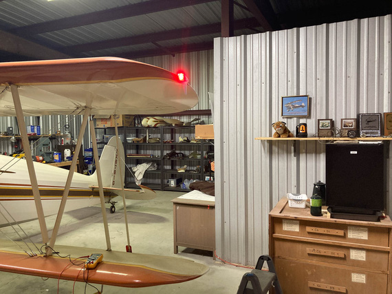
Let there be light!
The other fun part? On the left side, Remo had standard 6-32 tapped holes in whatever the backing of the light socket for the navlight was made out of. I couldn't really see - maybe a nutplate, maybe just tapped sheet metal.
But on the right side, he used sheet metal screws. Which, of course, I didn't know about till I started putting the lights on - because I took apart the left side when checking if SkyBeacon will fit, and assumed the other side would be exactly the same. As usual, rookie mistake. By now, I should know to check everything.
Well, that was a minor delay. Spruce / AN standard doesn't have screws with the right size head (#6 AN screws have heads too large to fit on the SkyBeacon and SkySensor), so McMaster-Carr had to be resorted to to get the right size and length sheet metal screws.
P-Leads
The Charger has the Bendix mags, and the P-lead connectors on those are not ring-terminated; instead, using a "screw in" type deal.

Bendix type p-lead connector - old wire
Basically, the shielded wire goes thru the outer bushing. The ferrule is a "T"-shaped sleeve, and shield get spread out over the "shank" of the T. It's squished between the outer bushing's base and the "flat" of the T of the inner ferrule.
The center wire goes thru an insulating spacer (that brown piece), and thru a washer on the other end - with a "button" of solder built on top of the washer to create a contact point.
The whole contraption gets screwed into the mag's receiving hole with the nut - ferrule rests against the mag's casing, pushing on the insulator and the solder button to contact the contact point inside the mag, while the nut pushes on the outer bushing and clamps the shield between it's base and the inner ferrule.
Now, that works with something like 16GA wire, and it's too big with my small 20GA P-leads. Also, notice how beat up the shield on that setup is? That's the old P-lead.
Folks make adapters for these to go to ring terminals, but they run something like $100 per, which is just silly, so I was determined to make this work.
Here was my idea, and what it looked like on the right mag. Note two P-lead wires - one of them goes to the front cockpit's tach.
We pigtail the shield.
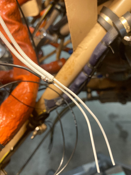
Shield pigtail
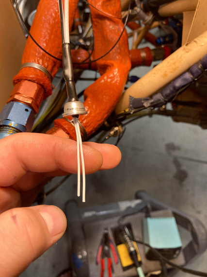
That gets heatshrunk - and the diameter is just right to go thru the ID of the ferrule.
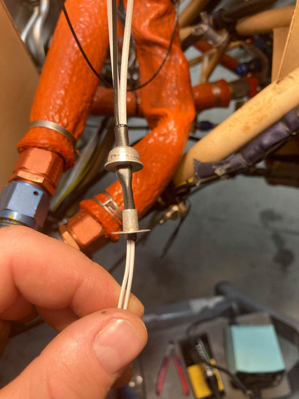
First layer of heatshrink, thru the ferrule
Then, the second layer of heatshrink goes over the ferrule, "sandwiching" it between the two layers of HST.
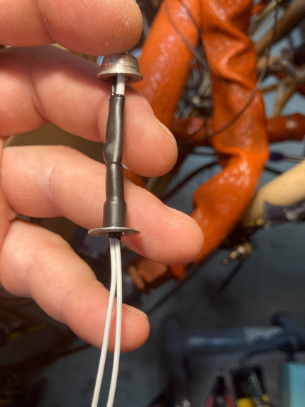
Second layer of heatshrink
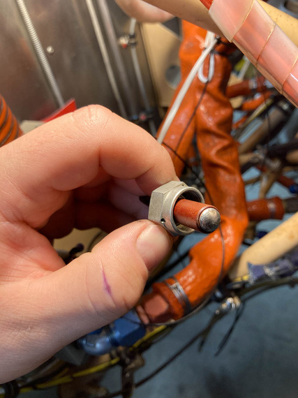
And with that, the bushing would slide over the outer heatshrink... but wait. Not so fast! The hole in the bushing's too small, maybe just by .010 too small, to fit over that layer.
Damn.
After playing with various heatshrinks for the outer layer, and trying to slide the bushing on while the HST was hot, I gave up, and...
... just enlarged the hole in the bushing. Yes, I know. The bushing seems to be CAD plated, and I surely took it off (the bushing was magnetic). We'll see how it fares - if I see rust, I can always buy the adapters for silly prices.
Bushing over ferrule covered in HST
And the rest is easy - fish the center wire (well, wires in this case, but same deal) thru the insulator, washer, and put the solder button on. Except that this is FWF ... hmm...
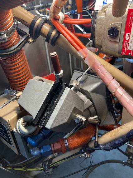
Soldering setup
Another exterme soldering setup? Well, not as much as the wingtips were...
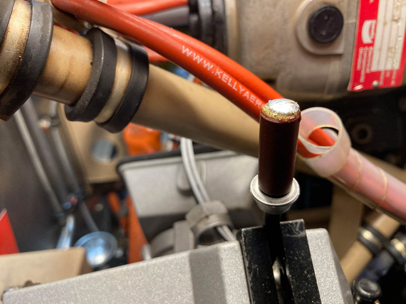
Solder button on and cooling off
All done
And, screw the whole deal in.
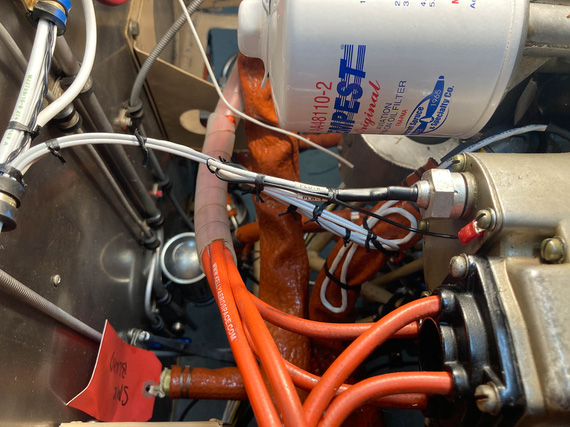
P-lead attached to the mag
FWF, finishing up
And then, the rest of FWF. The only other interesting tidbit was my thinking about the Starter Warning light wire. It's one that goes off of the "I" terminal of the starter contactor - which goes "hot" when the starter contactor closes - to indicate "starter engaged" with a light. The whole shebang is probably superficial, but I convinced myself that I wanted it if for nothing else than to maintain "symmetry" of lights on my panel.
Silly.
Anyway, that wire needed a fuse - though it's an intermittent wire, and I'll admit to thinking about maybe not having a fuse on it, decided to do it, because it wouldn't harm a thing.
Used a 1A "legged" type PCB mount fuse there.
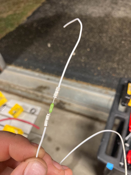
Inline fuse for the "starter warn" wire
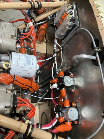
The rest of FWF was nothing interesting to write about... Contactors, fuel pump, monitor harness, and the like. Tons of knots.
Got rid of all the remaining zipties and plastic "coils" around the ignition wires, too.
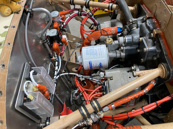
FWF - right side
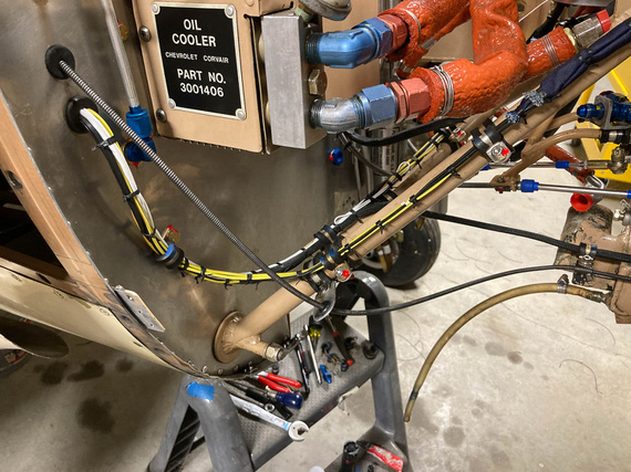
Right side - engine monitor harness
FWF - left side
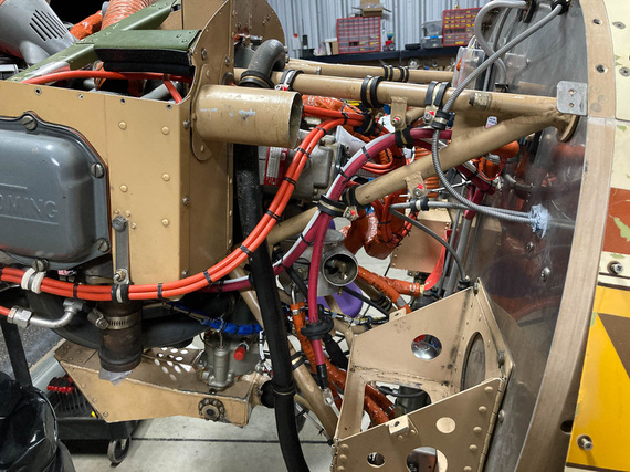
Left side - ignition harness, and battery wires
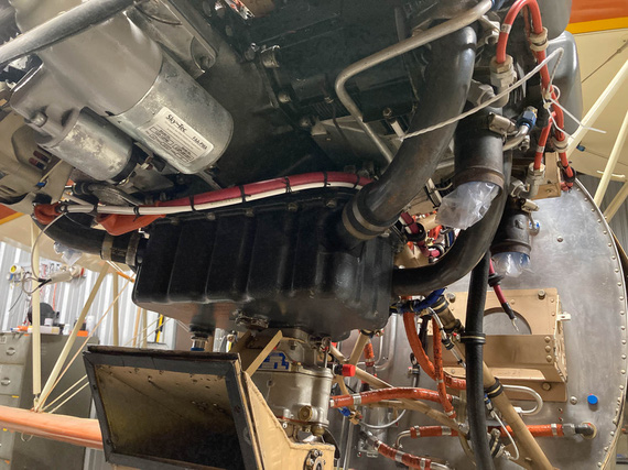
Underside - starter, and alternator wires
Flying is the second greatest thrill known to man…. Landing is the first!
Up ↑
Wiring!
...part one
| On: | Jul 26, 2020 |
| In: | [Chickenhouse Charger] Electrical Rebuild |
| Time logged: | 95.6 |
| Tags: | 6781G, MA5 Charger, electrical, soldering, fwf, panel |
Well, damn. With almost a year (no, more than a year!) of my being a caretaker of the Chickenhouse Charger, I finally was about to actually begin what I have started - which was, putting in my wires.
I decided to start at the switches, and run from the panel forward. Some wires will terminate at the fuse blocks (power feeds), and some will go forward - to the front panel, voltage regulator, and firewall forward.
Then, I was planning to run a few wires backwards - the ones that were pre-terminated on my transducers (fuel, oil pressures, oil temp, and mag pickup for the tach).
Immediately, I will admit: that was a mistake. While the harness turned out alright, it could've been much neater - if I ran in one direction. I could've made sure the whole thing is wire to wire and perfectly clean. So I should've run front to back, because my pre-terminated wires all "started" upfront.
In other words, prop to tail. Well sigh. Next time. On the other hand, this approach would've made terminating switches at the panel a nightmare. That was, initially, the reason why I wanted to start at the panel - so that I'd pre-attach wires to switches, tie them up, and then trim them at the other end.
At any rate.... Shall we?
Prep
Couple things to knock off before I started wiring was to complete the back panel. One thing that was left was the compass correction card bracket. No problem, drilled and tapped a couple holes for #2 brass screws.
Here's Mr. M. installing it:
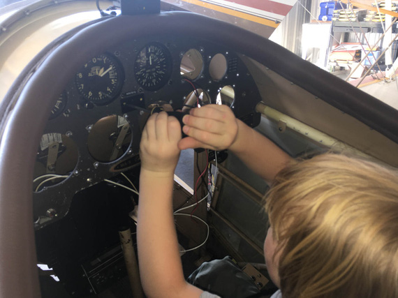
Compass Correction Card Bracket
The other one was the inertia switch for the smoke system. Glenn had it in for "safety": in the event of a shock (crash?) the switch breaks the circuit. I am.. not sure why he would have it, but he had it.
I considered not putting it back in, but what the hell.
Here's the switch:

Shock switch
The problem was, it sat tightly between other switches in the panel. With old layout, that barely worked; but with the new layout, and Honeywell double throw switches, the connector plug was getting in the way. So I had to resort to some vandalism. :)

Removed the connector and the shroud
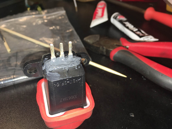
Epoxy around the tabs
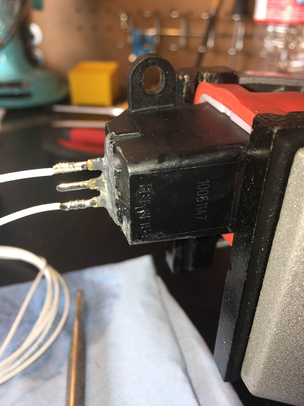
Solder!
And the switch fit nicely. Here it is, tucked between the switches. You can see how that connector would've interfered.

Shock Switch between other switches
The final prep thing was enlarging two holes for ground points to #10 and cleaning the back side up to expose nice shiny aluminum.
Panel
Now ready, I decided to install the switches first, and then wire them from the back. I needed a couple short jumpers though to connect them, and to set up some wires to be the exact length. That'd be impossible with switches installed in the panel (too little access), so I set up an old placard plate, installed switches into it, and worked on those jumpers and terminations on the bench before moving them to the airplane.

Switches on the bench mockup
Here's a couple more pictures of soldering and terminating fun pics:

Warning light socket
(that flux got cleaned off, of course).
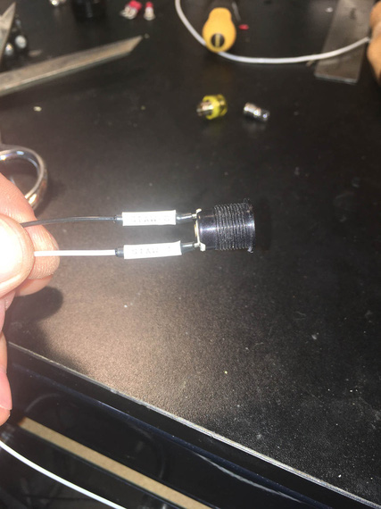
Tagged and shrunk
The heatshrink I'm using for these and in fact all my soldered joints is special strain relief kind with glue in it, specifically, Raychem SCL. It's 3:1 and it is very rigid - almost completely rigid. It definitely adds more support than the typical PIDG crimp used everywhere.
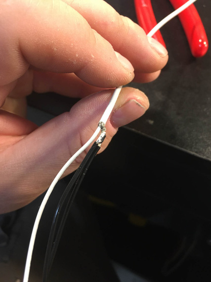
Pigtailing shielded p-lead
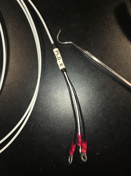
Finished with rings, HST, and tag
And then, switches went in, got tightened and straightened up, and I started running the wires.

Somewhere in the middle of running the wires
I think it happened when I was yet again sitting in the cockpit, clicking the switches and enjoying the very well done Honeywell's action.....
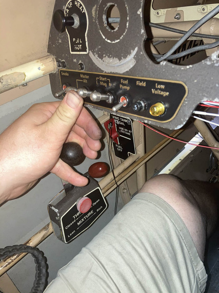
Engine starter engaged position - note that I can hit the starter and hold the throttle with the same hand
...when it dawned on me...
My three most important switches, L and R Mags, and Master, were set up with lockouts - you couldn't turn them on just by clicking them, instead, having to pull the lever first to move it to the "on" position. I mostly did that to protect from accidental too playful a kid in the cockpit.
But they weren't locked out in the "on" position!
Why is that important? Well, the Smoke and the Fuel Pump - the most operated switches on this plane - are right there. Note how their levers are shorter? If I accidentally hit the longer levered Master, or a Mag, switch, that would turn it off - with me potentially shutting down the motor. While a remote possibility, improving the situation would amount to just replacing the switches to the ones with lockouts in both on and off positions.
I don't know how I missed that when designing the original setup...
I decided to do it.
So out came the switches, I had to un-wire the terminals from the back. In went the order for three new switches with now correct lock-outs.
About a week later, I had them, and could proceed.
With left side wired up, I could tie it down. Mind you, access there is tight and from all kinds of weird angles :).
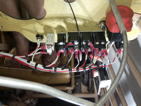
Tying left side
Some of those knots I did from the side. Some I did while sitting in the cockpit, using mirror as reference
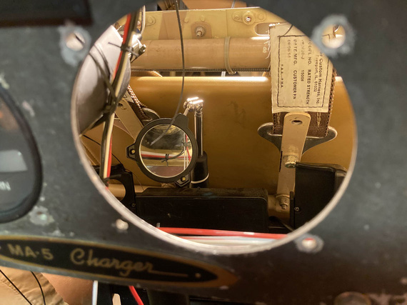
Look in the mirror!
Then, some "extreme soldering" to extend the panel lighting wires, that turned out to be a hair too short.
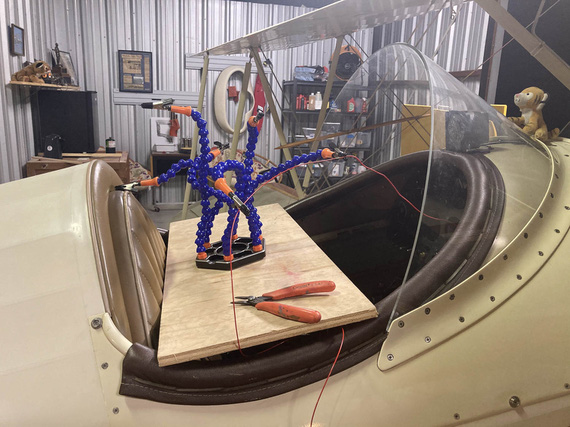
Extreme Soldering
For those lighting wires, and for the turn coordinator, routing took some fiddling with. My initial plan would've had them rubbing against the sides of the gauges, and I decided to bring them "out" and away - that's why I had to extend them, by the way.
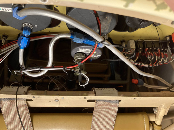
Lighting, and turn coordinator wires, test-tied
Note no padding on that pitot line: this is a temp, "sizing" pass: I am yet to finish assemble the back panel, and will add the right padding then.
The right side of the panel was much easier - it held much smaller, and simpler circuits, for lights and turn and bank.
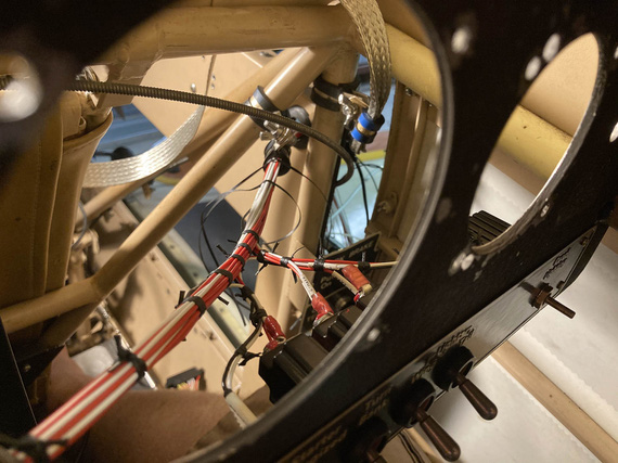
Right side
You can see the beginnings of the ground strap to bond the panel with the "side conduit", holding the fuse blocks and being one of the grounding points. In my original design, I had firewall, motor, "side conduit", and panel, as ground points - all bonded with those straps.
Here's the right side:
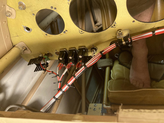
Right side
and the bonding strap
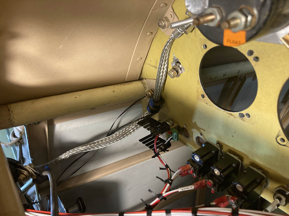
Panel bonding strap
(the bonding strap got enclosed in super flexible heatshrink just for neatness: this is a fit-up picture).
I also had some fun with ADELs right where the wires turn from the "side conduit" towards the panel. I had to clear and negotiate a couple bowdens, and the engine monitor harness was unwieldy.
I think that took a number of hours, just trying various setups, the final one that I really liked was this:
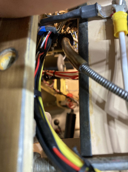
Engine monitor and carb heat bowden.
I replaced all the ugly zipties with lacing, of course :).
Meanwhile, on the outside, to keep the wires nicely separated, I spread them out in kind of a "fan" in the order they ran, back to front:
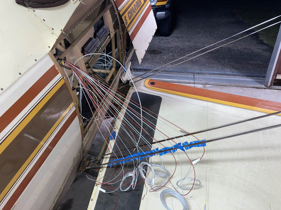
Wire fan
A day later, I replaced the tape with a comb. Yep, a cheapo $1 comb :) Worked out great.
And finally, before committing and continuing, I checked each wire for gauge, and proper circuitry.
Side Contuit, Part I
With all those wires sticking out, it was now time to start figuring out routing in the side conduit. All the wires that had to go forward had, well, to go forward.
After lots of fiddling, I ended up with this:
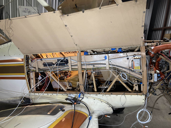
Initial stab at the side conduit routing
I had to clear all the brackets, and other sharp things. Ended up adding a couple more ADELs (and drilling holes in the conduit to accommodate). Also, reused some existing holes, made a few standoffs for ADELs and such.
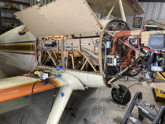
Another angle on the side conduit
And that was it for now. Now, all the other wires needed to join the main harness in the side conduit.
Front Panel
The most interesting piece in it was a Westach tach, that fed directly off of a P-Lead and required a .25A fuse. Glenn used a 1A classic glass fuse, but I decided to do it right. See, the thing is, if it fails "short circuit", that'd turn off the mag - I guess that's why the fuse is in there.
The tach would get another 20GA shielded wire, just like a p-lead, and I decided to join it to right mag's p-lead at the magneto - instead of splicing it into the p-lead running front to back in the side conduit.
But, back to the fuse. I figured, I'd build it into my connector that hooks up to the tach. Then, if blown, the connector could be rebuilt. Yep, it's more annoying than a regular replaceable fuse, but that circuit is not critical, and I had no room for a "regular" fuse block or holder.
So I got me a "legged" .25A fuse with a massive voltage rating (I forget what it was, but definitely above what a mag makes), and hooked it to a regular Molex pin.
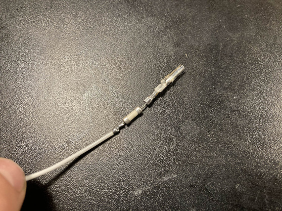
Inline fuse
Finished with SCL, it's encased in a plastic tube and is not moving anywhere. There's two layers there, actually: one around the fuse and the pin, and another around the housing and the inner layer.
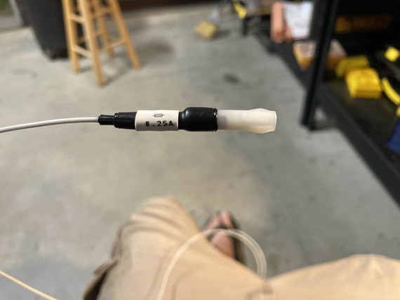
All finished
The final connector got set up like this:
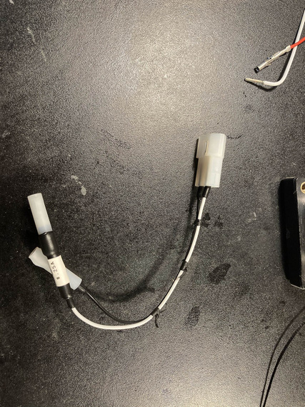
Inline fuse and connector
... and it goes on the tach like this:
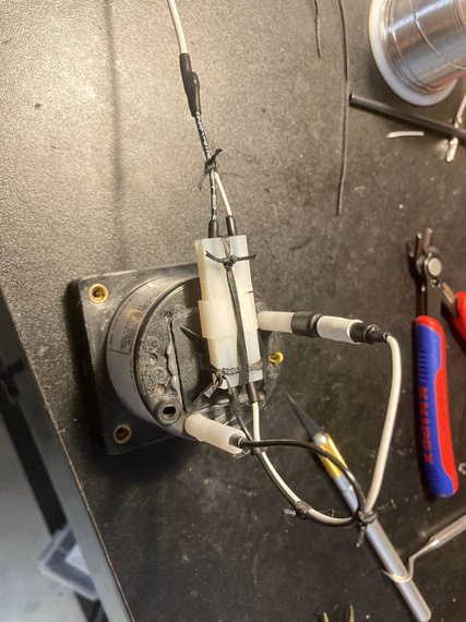
On the tach
The lead is just a regular pigtailed P-lead, of course. Notice how I like using SCL around individual Molex pins for added strain relief - that's because I can't produce good Molex crimps that I like; and I end up post-soldering them in addition to crimping. That strain relief ensures that soldered joint is firmly held immobile. Takes a bit of extra time, but I actually like that better than straight Molex crimps.
The rest of the front panel wasn't interesting, just annoying. There's only three circuits there: nav lights wires from the left wing run along the back of the panel to the right side where the conduit is, and then there's hobbs and tach, and that's it. It was just very annoying: with very little access, not being able to see things, and, being in the front hole, having to climb out and in every time I needed a tool I forgot to put close (when in the back hole, I can roll up a cart to it and have all my tools there).
Mirror was absolutely required.
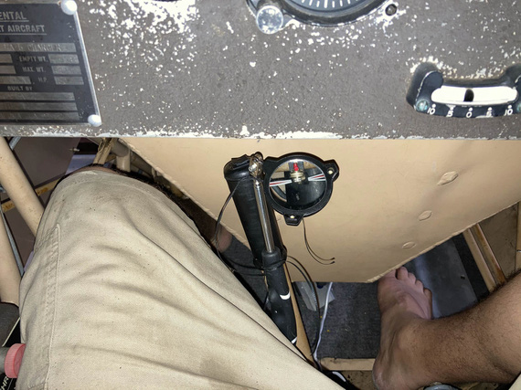
The only way to see things
I will admit to asking my dentist right around this time if he had a trick up his sleeve for this kind of mirror work. Of course, he said. Practice. Lots and lots of it.
Okay, so the front panel got done, and it's wires merged with the main harness.
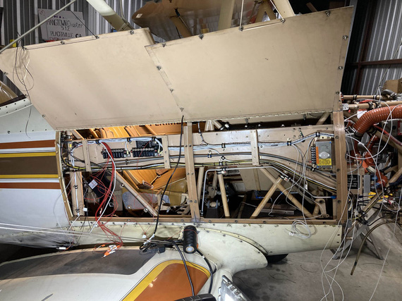
Front panel sub-harness joining the main
There, see, it's that small bundle going up and disappearing from view right in the middle of the "conduit"? That's the front panel sub-bundle.
Firewall Forward
The final set of wires to join the main harness were all the wires coming from the firewall side - mainly, transducers and other instrumentation wires, but also a couple wires for the voltage regulator.
This was precisely when I realized the mistake I talked about in the beginning - and ended up with less neat, and more tortured harness. Oh well.
I started up front, trimming and terminating my fat wires for the starter and alternator B-feed. Some more extreme soldering (to cap them), this time with a torch.
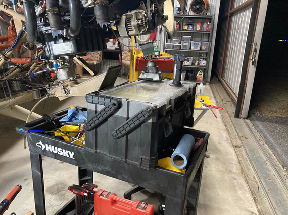
More extreme soldering
I tied up, and clamped the fat bundle to the motor: and apparently, didn't take a single picture.
Then, I had to figure out the diode for the Starter contactor - first of, it needed longer leads. There, instead of soldering, I used small barrel crimps from Molex along with heatshrink (I do use them where soldering is impractical, and I decided not to have soldered joints FWF).

Diode with leads

And all enclosed
And then, a simple ADEL to hook it up and hold it
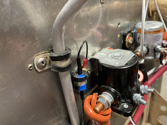
Diode all hooked up
And then, the ammeter shunt, and the sense wires. Those needed fuselinks - in liew of an in-line fuse. Simpler, and cleaner this way.
I tested them a while back, and am confident they'll work.
First, we take a wire 4 "gauge steps" thinner than the fused one (so 24GA for 20GA fused, etc). That goes into the "source" terminal.
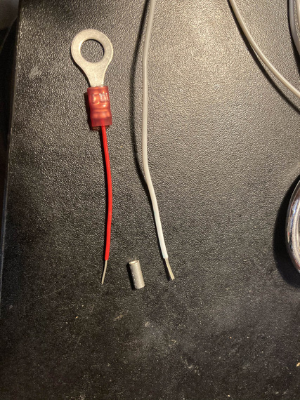
Beginning of the fuselink
Then, we hook it up.
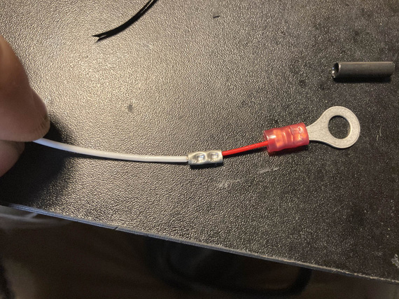
Hooked up to the protected wire
Then, some heatshrink over the splice, for strain relief.
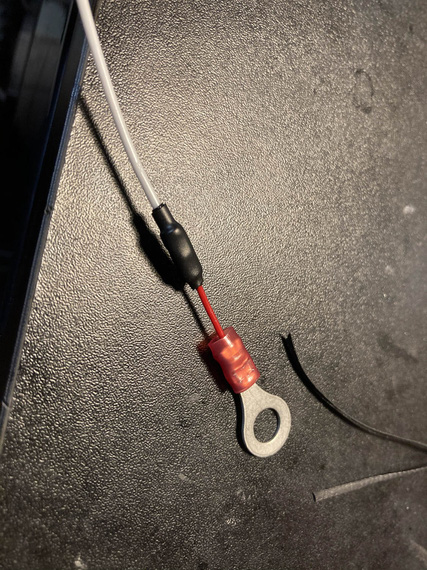
HST
Then, a bit of fiberglass sleeve to contain the "fire" when (and if) it does it's job, as in, burns thru the thinner wire that acts as a fuse in case of a short.
A bit of marking too. And a "cap"
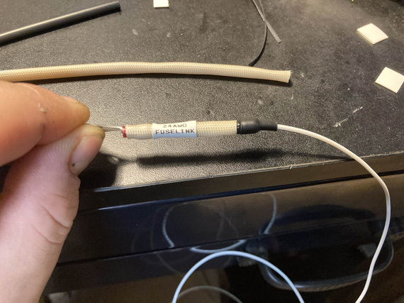
Capped and labeled
And finally, a couple knots to hold the sleeve better.
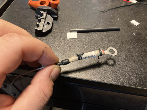
And laced
And finally, I finish installed all the engine transducers: pressures, and oil temp; and routed all their wires back into the side conduit and thru it back to the cockpit, adding them to the main harness. And that was that, for now - I plan to terminate them later.
Tail Light
I got rid of the belly strobe on the plane, because it was too heavy and too.. useless. Wingtip lights are gonna be the SkyBeacon and SkySensor from uAvionix (my ADSB mandate compliance :) ), and they have strobes: but they're not visible from the back. So I decided to replace the tail nav light with an LED nav/strobe.
Problem number one: no ground wire going to the tail light. For whatever reason, Remo decided to basically use the fact that the tail light is hooked up to the rudder with a pair of screws thru sheet metal of the rear rudder bow... I don't even want to begin to think what the ground path would be: hinges? control cables?
So, I needed a second wire.
Problem number two: it had to be one neat cable, and it had to be of a smallish diameter (Remo had an old 20GA wire, which is thicker than modern 20GA tefzel wire).
I decided to use a chunk of 20GA shielded - same ones I used for p-leads. Technically I guess you're not supposed to do that, but it's very far from all the antennas and I'm crossing my fingers that it won't create too much problems. Thickness was spot on.
So, I soldered the new piece to the old wire, and fished it thru using old wire as a pull. That part was scary - if that didn't work, I would've had to cut holes in the rudder to get a new wire thru.
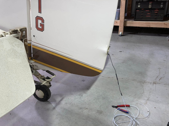
Fishing a new wire thru
The tail light shipped with a small Molex. Why not?
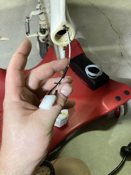
Connector terminated
The other end went onto the light, and everything got hooked up
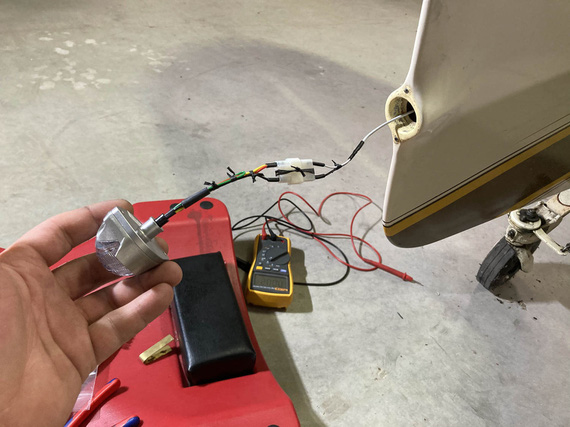
All hooked up!
On the other end (on the tail fin side) the wire went into a hole on the inspection cover, and had to join the wire coming from the front. And I had to have the ground there. You can see that area right behind the elevator on the "fishing wire thru" picture.
Problem number three: nothing to hook up the ground to in that area. The only option I figured out was to use one of the rivnuts that are attached to the tabs welded to the frame, hoping that there's no corrosion there between the aluminum rivnut and steel fuselage. I figured I'd use a way too long a screw thru one of the rivnuts when attaching that inspection cover, and then pull the ring terminal onto it, and secure it against the back side of the rivnut with a nut and a washer. Ugly? Yes; but I didn't have any more options. Really, the right way to do that would be to run two wires from the pilot panel all the way back, but.. I'd have to start cutting fabric for that.
So, I attached the positive to the wire that was already there, terminated my ground, hooked everything up, hooked up some power, and...
Nothing.
A bit of debugging showed that... ground was the problem. Damn! I picked the wrong rivnut, I guess - it had corrosion. The one right on the other side though showed the right voltage when measured against the positive lead, so I just moved everything to the other side, and...
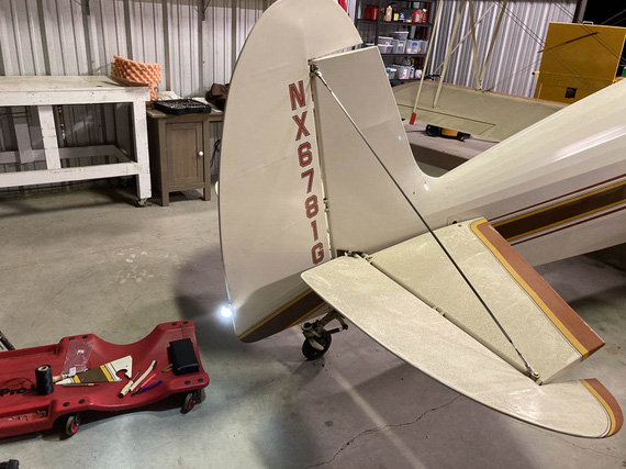
Let there be light!
Side Conduit, Part II
At this point, the main harness looked something like this:

Main harness: complete, but not terminated
Now was the time to go thru it, cockpit to firewall, and terminate all the fuseblocks, and tie and zip everything up.
First, conduit, cockpit side. Lots of crossing things, lots of padding for bowdens where they cross the wires (I used the right sized vinyl tubing from my local friendly Aerospace Depot, and lacing to tie it).
Engine monitor harness got covered in tube for quite a distance - there was no way to keep it off and not rubbing on the conduit.
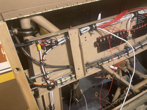
Cockpid side conduit
Fuse blocks got their placards. No, Mr. D., I am not doing brass placards again!
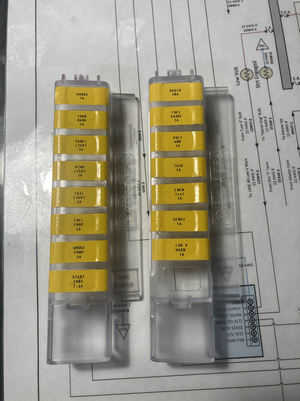
Fuse block covers placards
And then, slowly, methodically, every power wire got it's ring terminal. I added a bit of a "service loop" and used a ruler to try to keep each next wire exactly the necessary amount longer to reach the next terminal screw... Didn't work out too well, but close enough.
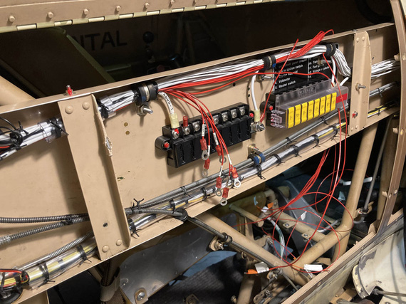
Rings!
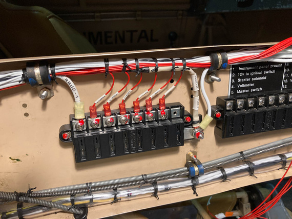
Tied up and hooked up
Another side got the same treatment, and then...
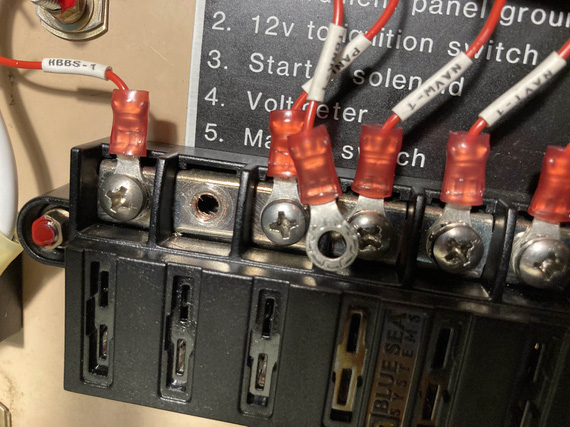
?!?!?!
Did I just strip a terminal block hole?? Yep. I did. I blamed a bad block and definitely, positively, absolutely not my overtorquing the screw. Nope. No overtorquing. For sure!
So, had to get a new block. They're $35 so I figured I won't try to repair this hole to use an upsized screw....I'd spend more money on shipping small-headed #10 screws (the screws in the terminals are #8 but with small "oval" rather than "pan" aviation style head, so I'd have to get me some decent screws from McMaster.. by the time I'd be done, it'd be close to those $35).
So, fuseblocks. From there, it was just turning everything pretty.
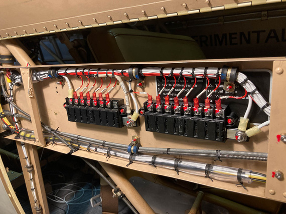
Both fuseblocks done and tied
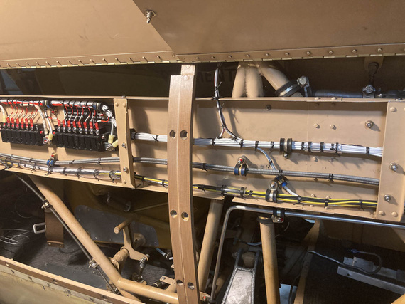
Mid section
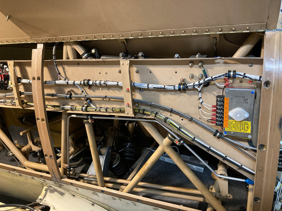
Voltage regulator
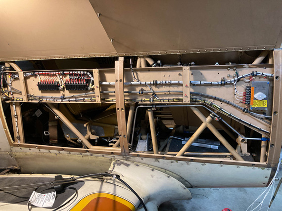
The whole thing
Sorry, couldn't resist doing a "before" picture.

Before
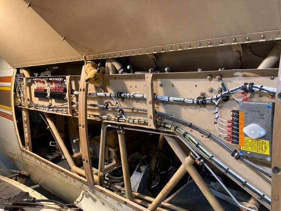
Jack likes this!
It at first you don't succeed, well, so much for skydiving.
Up ↑
Engine Monitor Wires
... firewall forward
| On: | May 01, 2020 |
| In: | [Chickenhouse Charger] Electrical Rebuild |
| Time logged: | 7.6 |
| Tags: | 6781G, MA5 Charger, electrical, fwf, engine monitor |
This was a small project to wrap up everything I could do firewall forward before moving on to the panel and main wiring.
I wanted to clean up the engine monitor probes harness. When Glenn installed it, he used zipties everywhere (and actually everything on the plane was ziptied). Nothing wrong with that, except where zipties were used around motor mount and the like without any cushioning.

Probe wires with zipties
But last I checked, zipties weren't used in the 1930s. No, in the 1930s grass was greener, trees taller, water wetter, and Real Men used wire lacing to tie their wiring harnesses together.
And using adel clamps on round tube is just good karma.
So, I re-did one side first.

Properly laced and mounted
Much better isn't it? Those wing nuts are temporary - I will replace them all with real ones when finishing up FWF much later.
I did the other side, though didn't tie it up yet - there will be more wires joining that branch later, and I had to wait until they were done. But, I did set up all the adel clamps - about 4 pairs of them total.
Next, came the carb temp probe. I had to extend it's wire, and hook it back into the main harness. I repositioned it a long time ago because I ditched the Rotec TBI, and the old wire was just a touch too short.
I spent quite a bit of time making sure that it's a thermocouple, and that I can reliably extend it - with same material and type thermocouple wire. I did some basic tests with extending it and making sure it shows reasonable numbers. It did.
I thought a couple times about ditching it; but decided to keep it if I could, and my tests showed that I could do that.
Mounting and routing ended up looking something like this:

Carb temp probe wire
From there, it'd go straight to the motor mount (towards the firewall), and join the engine monitor harness.
When extending the thermocouple, the easiest thing to do is make sure that the joining thermocouple wires mesh together - this way, you're not introducing a section of a dissimilar metal between two segments.
To do that, I used simple Molex "barrel" butt splices that allow you to put one wire on top of another and crimp around. You then heatshrink the joint. In fact, I'm starting to like them, and am thinking about using them instead of the usual AMP butt splices with nylon insulation. They are much cleaner and compact, and heatshrink I use here (SCL) provides ample strain relief (it shrinks to hard plastic, and glues itself to the wire).

Extension being put on
I shrunk each crimp individually, and then another chunk around the whole thing. The whole thing was set up to be held by a second clamp (you'll see it in the picture a bit further down).
Back when I installed the CGR-30 on the Cheetah, I encapsulated all the probe wires into fiberglass sleeve, and here it'd fit perfect - to support the lonely wire spanning about a foot to the motor mount.
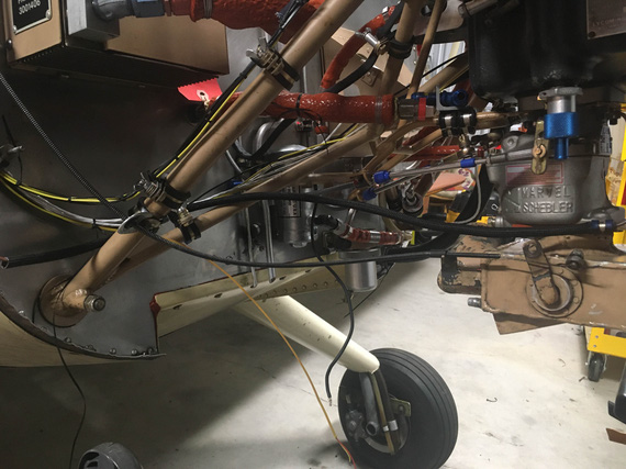
Fiberglass sleeve
I also used CGR's "barrel connectors" to hook up to the harness end. They have the wires "mesh" together, and fix them with a grubscrew, making the whole thing removable. Not sure when I'd want to do that, but I wanted to have an option.
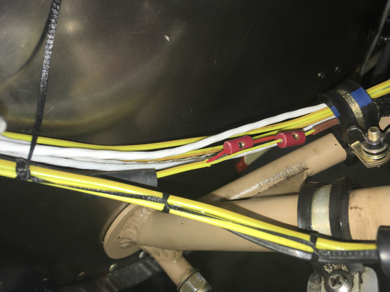
Barrel connectors hooking up to the main lead
Before closing it up, I tested everything. The probe had to be in the carb, so the best I could figure was to check if the ambient reading was good, and then heat it up and make sure that was reflected.
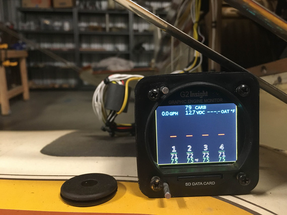
Testing
That was good enough for the test.
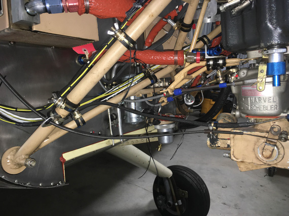
All closed up
Turned out pretty nice methinks - and I didn't have to lose the probe. The joint between the extension wire and the probe wire is very close to the adel clamp holding the fiberglass sleeve to the airbox, on the right side - and remember, it's in hard plastic that the heatshrink that's under the fiberglass sleeve turned into - so I'm not concerned about the joint failing there.
When a forecaster talks about yesterday's weather, he's an historian; when he talks about tomorrow's, he's reading tea leaves.
© Copyright "79FT". All rights reserved. Feel free to cite, but link back to the pages cited.
This website only shows how I did things in my various projects. These pages are for information and personal entertainment only and not to be construed as the only way, or even the perceived correct way of doing things. You are responsible for your own safety and techniques.
