[79FT]: Building Things |
 |
Cleaning up Light Coves on Wingtips for Cheetah
... I hate sanding!
| On: | Jul 03, 2015 |
| In: | [Misc] Cheetah |
| Tags: | 9891U, mechanicing, fiberglass |
In the past 7 months I have been busy building... the crib for the baby. Almost non stop evenings, 4-6 hours a day: the result is good, but this is a "Skybolt Story", not a "Bed Story": so no, I won't post all my projects here :).
Also, it seems like next 2-3 years will be mostly furniture building for this guy.. Oh well.
Meanwhile, I was able to put in a few hours into fixing up the coves in my wingtips where all the lights are.
If you recall, I have made strobe shields quite a while back, but I haven't fixed up the coves. I was waiting for the shields to be painted.
Well, they were during the cgr-30 install, and then I was working on the crib.. So finally, the time has come.
Look at what I had to start with.
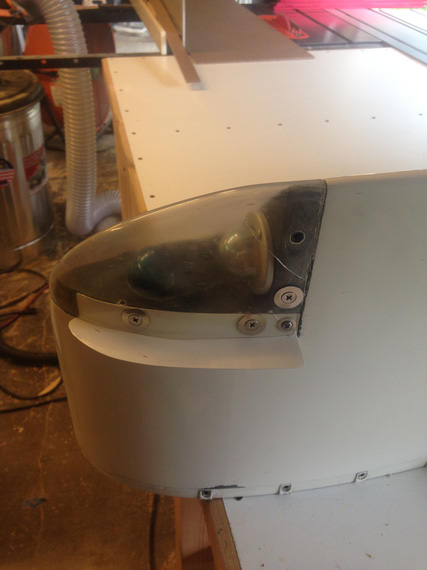
Sad sad wingtip
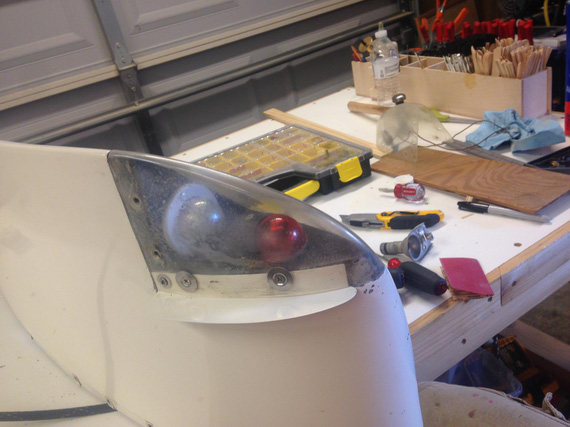
Another sad wingtip
First, all the lights came out. The old plastic lenses went straight into the trash bin. Then, came off the foam padding that goes in between the lens and the wingtip.
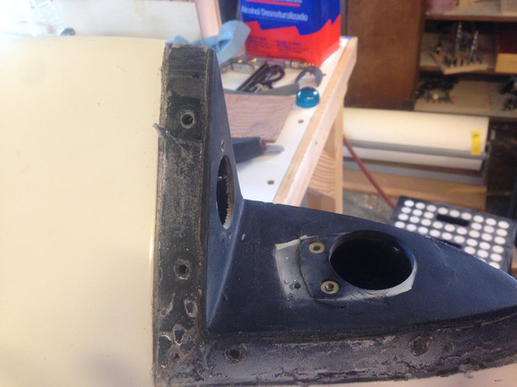
All opened up
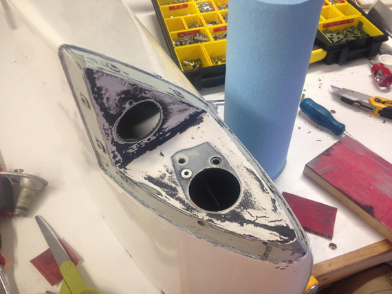
Cleaned and sanded
I think the above was about an hour of sanding. All old paint came off. Also, the broken rivnut went out (did you notice it? That extra hole was what someone has drilled and used a sheet metal screw to "fix" it instead of drilling out the broken rivnut).
Finally, masked with the first set of masking tape. I was set to repaint the coves.
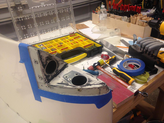
Masking the edges
The other wingtip was even worse. The cove itself had a huge "dip" in it. Also, some "genius" decided to screw #10 screws straight into the fiberglass... Some threads were all torn up, and I decided to install rivnuts all around to make sure the tips match.
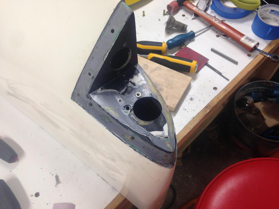
Just disassembled, note the large dip in the nav light area
In with Bondo! Lots of sanding! Oh man, I hate sanding...
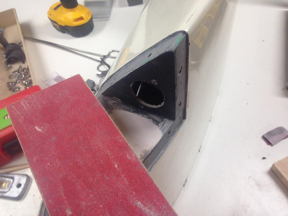
Bondo, and sanding...
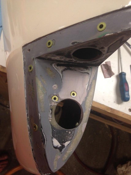
Done sanding
Phew. Quick fit of the strobe shields over the rivnuts, needed to enlarge the holes...
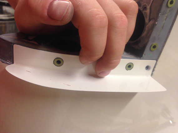
Fitting holes in the strobe shield
And we're ready with the second one.
Now, I wanted to clean up the nav lights housing as well. Originally I wanted to paint both cover and base, but once I cleaned up the base, I decided to leave it as is: apparently, it was nice and shiny after all that 40 year old corrosion cleaned off of it!
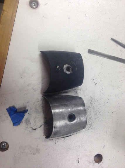
Nav lights covers. Second one was cleaned up as well
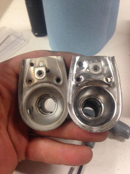
Cleaning nav lights bases. Shiny!
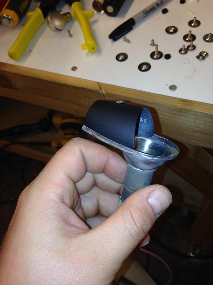
Came out nice after painting!
Then, final masking, and painting. Damn! That didn't go so well. I didn't notice a fairly small dip in the other tip's cove, and the Bondo'd one got some pinholes. Time was running very short so I ended up leaving that as is.
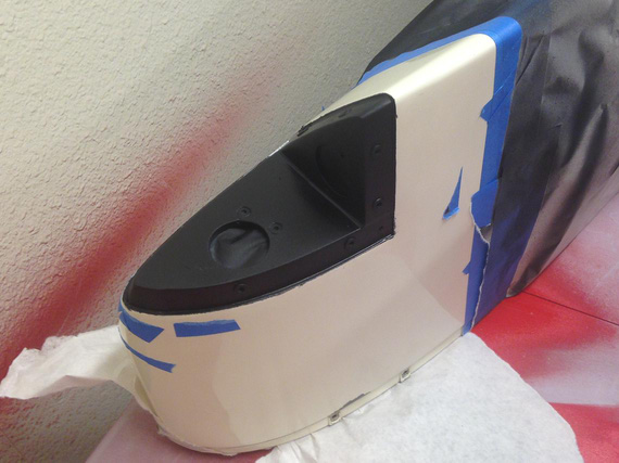
Right wingtip cove, painted. See the dip now?
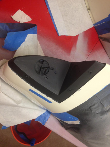
Left tip. That one with pinholes :(
Once the paint was all dry came the time for fitting the foam padding and lenses. And here, I made a fatal mistake: I have installed the padding first. That makes fitting of the lens virtually impossible (at least, for me).
That had produced an unsightly gap of about 1/8 inches. Oh god! I had no spare lenses, and I had to put the plane back together not to screw my partner who needed the plane soon. Very soon.
... I ended up screwing him anyway 'cause somewhere in the middle of me fitting that first lens Max was born and I was knocked out for 5 days ...
... just in case you're wondering: 7lbs 11oz, 20 inches, June 25, 2015, 10:35 am ...
... I still haven't had any chance to get another lens, so I decided to put it back together as is as a memory of me being stupid. Maybe I'll buy another set from Ken in another year or two; and also fix all the dips and pinholes ...
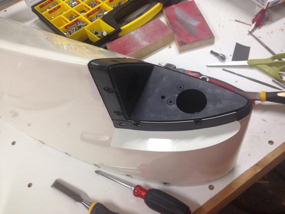
Fitting the foam padding
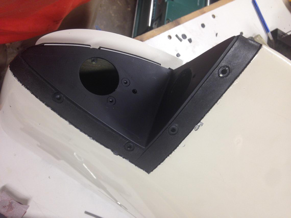
Fitting the foam padding (back side)
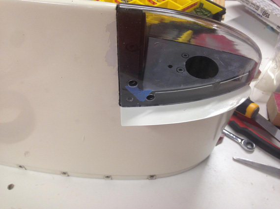
Top/front lens fitting
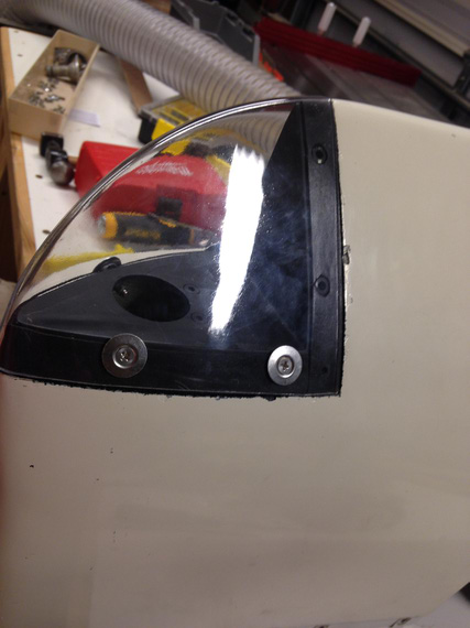
Bottom seams: see the unsightly gap?
I was much smarter with the other lens, and made sure to fit it before I put on the foam padding, and it came out perfect.
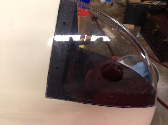
Fitting other lens. See no padding?
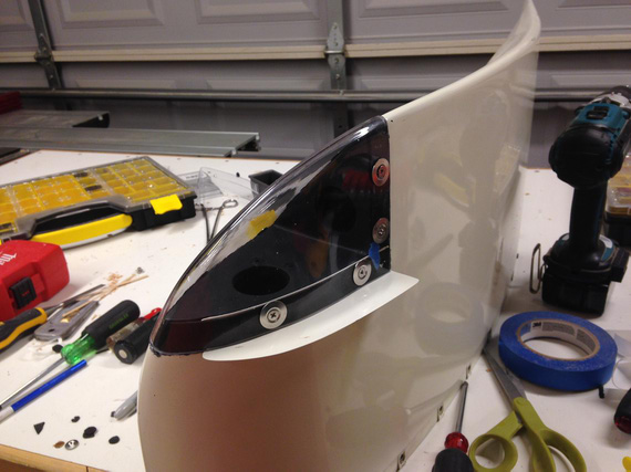
Padding on: and some holes in, too
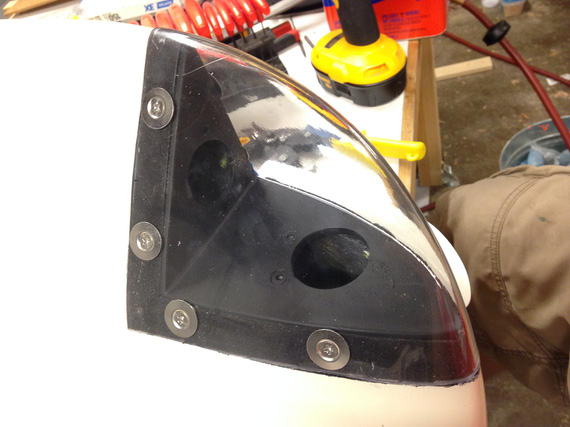
The other side
Then, I've put the lights back in, permanently screwed on the lenses, and I was done!
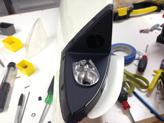
Installing the nav light base
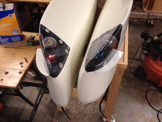
All done!
Much nicer than before, but with some problems. Still, much nicer than before.
Till next time (which-I-dont-know-when-will-come)!
"Approach UAL525 what's this aircraft doing at my altitude?"
"UAL525, what makes you think it's YOUR altitude, Captain?"
-ORD ATC
Up ↑
Strobe Shields for Cheetah
... fun with stretcher
| On: | Oct 24, 2014 |
| In: | [Misc] Cheetah |
| Tags: | 9891U, mechanicing, sheet metal |
No Skybolt news, you say?
Well, with dead alternator, tons of work, and unfinished install of a gauge that is supposed to keep you informed about your engine, not much time for the Bolt.
Oh well.
I love to fly at night. It's just something out of a different world, something... else.
There are a few things that are extremely important at night. Most importantly, the old "See and be seen" rule.
To be seen, you need blinking lights on your airplane, nav lights, ideally a landing light, and such.
To see, you need to retain your night vision. That means, no bright white or any color light besides something like red or blue. Otherwise, your eyes readjust for "daylight", and you are at good odds of not seeing other blinking lights... like the ones on an airplane you might fly into!
You see, I don't have strobe shields on my plane. Take a look at the picture below, and imagine you sitting in the cabin.
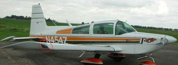
Strobe Shields on a Grumman
You see that vertical little metal "fin" I circled? That's what blocks you from seeing the strobe - a bright flashing white light. If that metal fin is not there, you basically get blinded every second or so.
It's so bad I ended up flying with strobes turned off a couple times I was up after dark. I figured, just one beacon on the tail and no strobes is better than a blind pilot.
And especially now, when the weather in Texas is so nice and night flying is just calling and calling and calling, that became a priority project.
So, on to it!
Those shields go under the wing tip light cluster lens, and the spot they're supposed to go into is curved. Shields themselves are nothing but a curved L - angle out of aluminum.
So, I needed a stretcher.
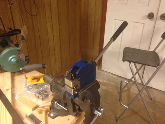
The Stretcher
Prepared one of the wingtips:
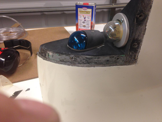
Wingtip light cluster with the spot where the shield goes cleaned up.
First, I decided to make a test piece to get some practice. Never used a stretcher before.
We start with a simple L-angle. I used 6061-T4, 0.025 thick.
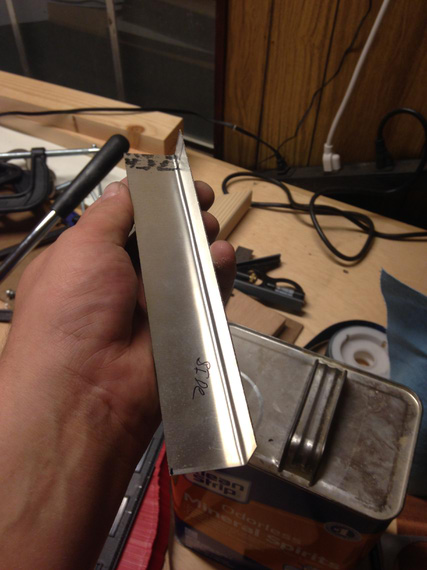
Simple angle
And then, stretch-check-stretch-check... Not bad at all. Just takes time.
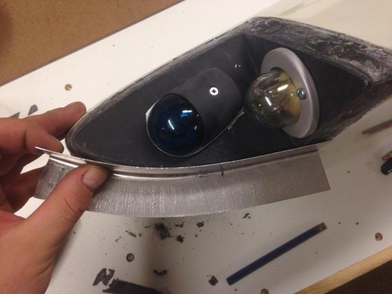
Stretching
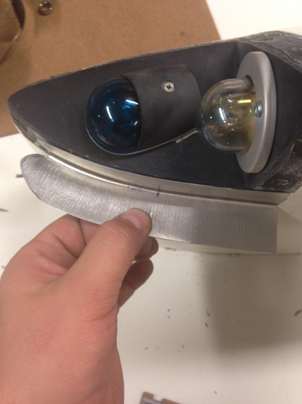
Close enough for a prototype.
You can see on the pictures that the stretcher leaves pretty deep "scratches". On the prototype, I tried sanding them out -- only to get my metal turn paper thin.
On the real one, I decided to fill them up with Bondo.
So, bought some, and made myself a pattern too -- which I printed full size.
To do that, asked Adam, the guy who bought my 28797's share (thanks again, man!) to take some pictures of strobe shield on his Tiger.
And then, just drew around it in Solid Works. Turned out nice.
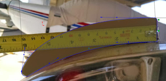
Sketching around the photo in SWX.
Note the tape measure above -- I first drew a line 6 inches long and scaled the photo until that line matched 6 inches on the tape measure. This way I ensured proper scale.
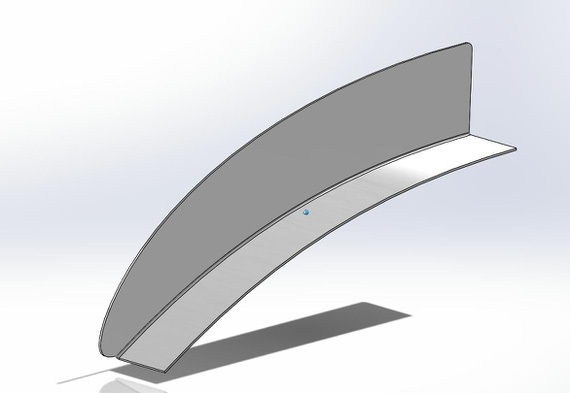
SolidWorks part for the Strobe Shield
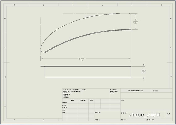
Drawing of the part for the patterns.
So with those patterns printed out, I went to town.
First thing I noticed is that curvature on the wingtip I was working on doesn't match the pattern :). Of course. They're all different (and by the way, on the other wingtip it matched perfectly. Go figure.). I wanted the pattern to primarily get the general shape right.
So, here I am stretching my L shaped angle, and... SNAP!
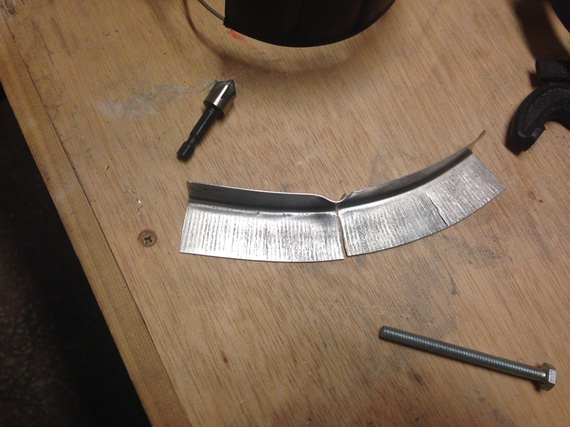
:(
So now, bend another L angle, deburr, clean up, size... sigh.. I went much much slower...
I think, getting it perfect took around 3 hours of careful work. That curve gets aggressive towards the end. And, when I was almost done.. snap! I tore it up again, this time the very tip.
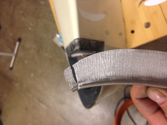
Damn!
Luckily, it actually still was long enough (I started with a piece longer than necessary), so I was able to get away with this tear. Phew.
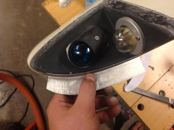
Perfect fit!
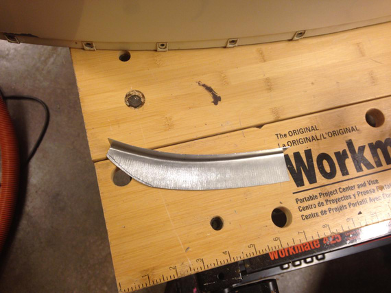
Cut to about the right size
Next, came a lot of sanding, filing, and emery-clothing to get it to the right shape. And then, the holes.
Those had to be duplicated and match up with the existing holes in the wingtip, so I made a simple hole duplicator. No, I'm not paying 10 bucks for that thing!
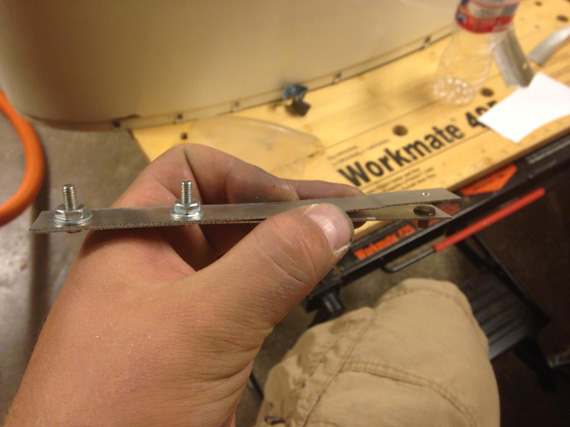
Homemade Hole Duplicator
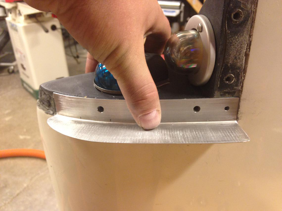
And, we have the holes.
Finally, I filled all the scratch marks with Bondo, sanded it down, and called it a nite. I think it was around 3 am then :).
Next day, the other wingtip.
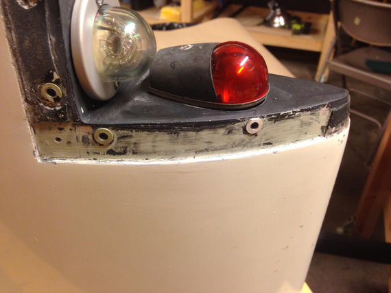
Prep
Notice that this one has rivnuts and not just holes. I now have a theory why this plane is missing strobe shields.
I think the guy who tore all the threads in the fiberglass wingtip and installed those rivnuts (remember, the other one doesn't have them?), was too lazy and didn't want to tweak the holes in the strobe shields to match with the rivnuts. That's my guess.
Initially, I thought about making oversized holes in the shield, but that would put one of them too close to the edge. Then, I tried filing the rivnut down a bit, but decided that I'm not gaining much there, and that notching the strobe shield base would be best. That's what I ended up doing.
I made just the first notch, and to stretching it was!
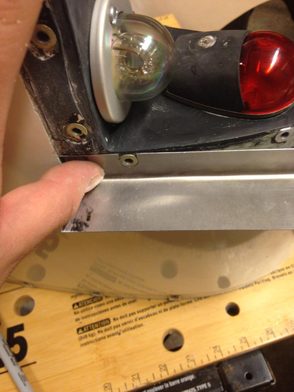
First Notch
When it was close to the other rivnut, I notched area around it.
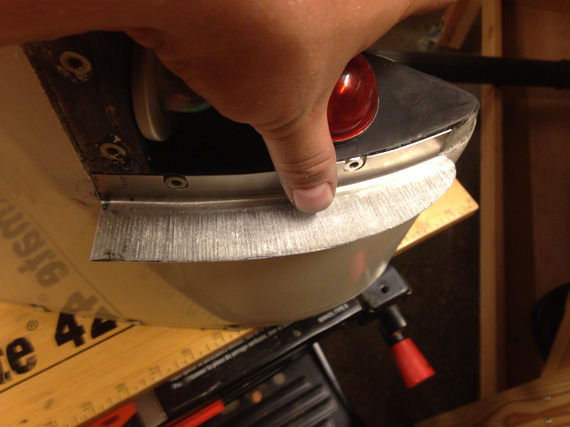
Secont Notch - close!
They came out perfect.
And then, tons of filing, shaping, sanding, Bondoing, sanding, washing, and...
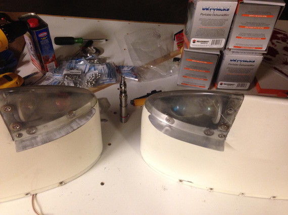
All done!
They're not quite complete yet. I'll have to clean up the rest of black tape from under the wingtip lenses and replace them with new ones, but that'll come after painting the shields. I'll ask Dave Fletcher to paint them into the same Imron he's gonna use for the (now soon to come) wheelpants.
And you know what.. that was fun!
If God had intended man to fly he would have given him enough money for a Bonanza.
Up ↑
Banging Sheet Metal
making bulges
| On: | Sep 03, 2014 |
| In: | [Misc] Cheetah |
| Tags: | sheet metal, cgr30, mechanicing, 9891U |
So on the Cheetah side, I am slowly ramping up for replacing all the engine gauges that I currently have on the panel with the CGR-30. I got it at Oshkosh, and finally, the box arrived a couple weeks ago.
Ain't she a beauty? Assembled on the bench for testing and familiarizing myself with it :)
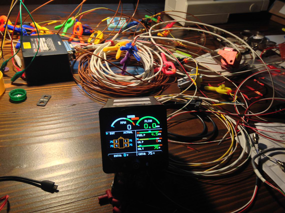
Ain't she a beauty?
Because of it, I will lose a few 2 1/4 inch round gauges, and I decided to make some covers for the panel, not to have unsightly holes in it.
Of course I could've bought them from Spruce or whatever, 5 bucks a pop, but if you know me, I would rather spend hours making something I can make. Besides, this is a nice first sheet metal exercise :). And, I wanted a nice domed bulge on each one of them. Just Flat wasn't enough.
So, I got to it.
First iteration was making a jig that would sandwich the sheet between two boards, with holes over and under the metal. Then, I would press a "piston" thru the holes using my vice as a press. Pictures are better than a thousand words.
Three piece jig + soon-to-be-'piston'. Oak boards sandwich the sheet between them. Ply plate has the "piston" and is used as a backing plate for it.
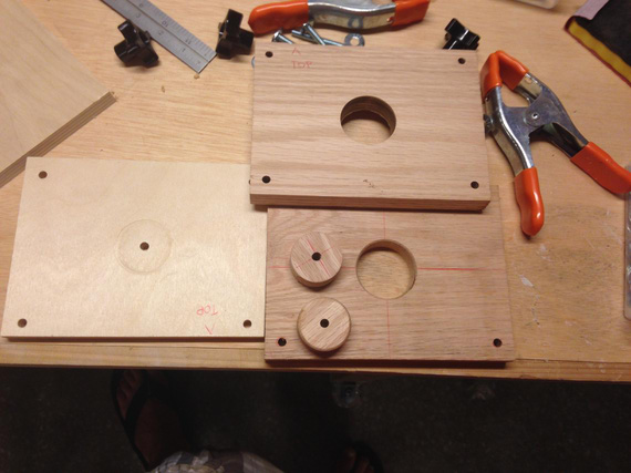
Jig pieces
That didn't work out. Vice jaws are not perfectly parallel, and the "piston" is not exactly the same diameter as the holes -- so it gets misaligned, even though there are four guiding bolts in the corners... Here's the jig assembled, and one of the first tries.
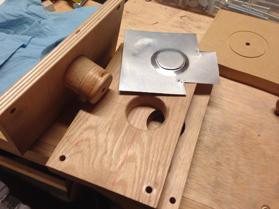
First try...
I think I tried it two or three times, with the same result.. no matter how much I tried to align the "piston", it would make a bit more pressure on one side of the jig than on the other, either resulting in a tear, or in an uneven "bulge".
Out of desperation, I took a piece of metal, laid it over one of the holes in the oak jig board, and started banging away - and was surprised! I was getting almost what I wanted, just not clean enough.
I tried sandwiching the metal between two plates and banging via the top hole - and made a fairly nice bulge! The edges weren't very clean, but I reasoned that if I opened the top hole up a bit more, that would give me access to the edge, and I will be able to bang on the edge a bit more, defining it better.
Ha! No. Same stuff.. I was able to make a fairly nice bulge, but the edge will be all "torn" and ugly.
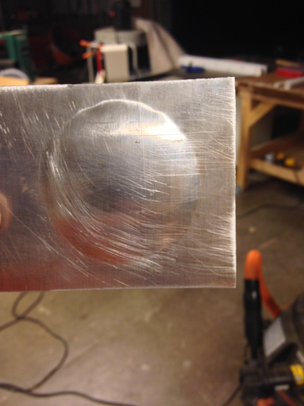
Bulge is there, but the edge is god awful
I also tried putting a profile on the bottom, "die" plate of the jig, with a very sharp edge and curvature under it.
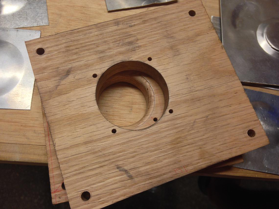
Second jig
No luck. I think I spent a couple hours, making over ten "bulges" and trying different hammering techniques...
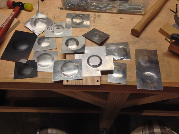
All those tries.
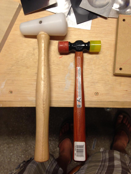
The Two Hammers
So I gave up, and emailed Bill Rose, the gentleman who gave me all the SolidWorks parts for standard HW, and, in general, helps me a bunch with my silly SWX and other questions, for advice.
Bill suggested using MDF for the jig instead of oak. Apparently, irregularities in wood grain would make it hard to define the edges uniformely. He also suggested using corking tools akin a big "chisel" on the edges to better define them.
..and.. it worked!
The third jig is ugly, but it works. Upper hole is enlarged just to get access to the edges (I didn't bother making the top hole concentric with the bottom or even round; there was no need).
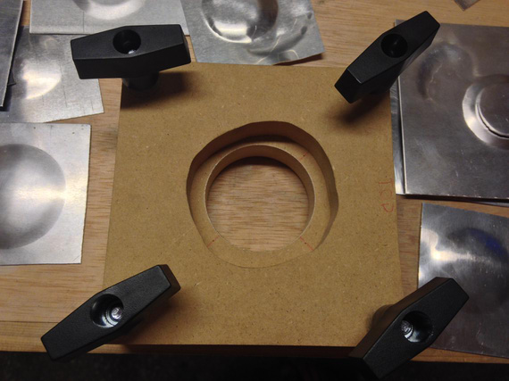
The third jig
I used the two-headed plastic/rubber hammer's rubber head as a corking tool, lightly hitting it with the plastic mallet, and having it slide from the edge into the center of the bulge.
This bulge still has some "orange peel" on it and needs to be smoothed out, but the edges are very well defined!
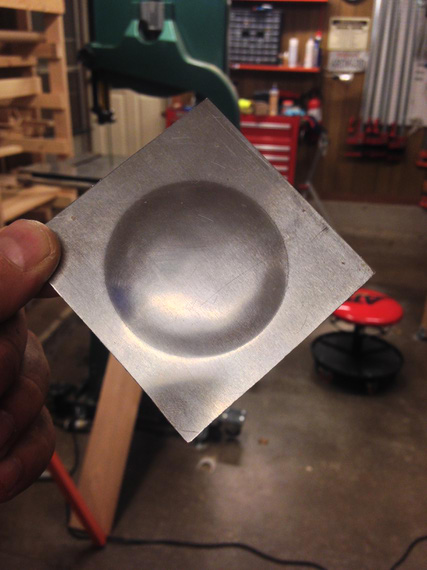
Check out those edges!
But of course, I screwed up again - the hole in the bottom, "die" plate of the jig, is of a wrong diameter (I used the wrong holesaw). But hey, at least I think I figured that technique out!
Good evening in the shop tonight :).
Why did God invent women when airplanes were so much fun?
Up ↑
Messing with Cheetah, Footstep and Friends
... all in TX summer
| On: | Aug 18, 2014 |
| In: | [Misc] Cheetah |
| Tags: | 9891U, flying, mechanicing |
Weekends are plane days now. I fly to my friend's hangar and mess with 91U, the Cheetah (I still need a name for her :) ).
This past few weeks Ive been doing little stuff here and there...
Cleaned up the nav lights lenses.
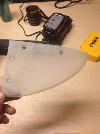
Before
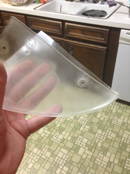
After
... they still look like crap, so I'll probably bite the bullet and buy a set of new ones.
Oh, and I need to make those vertical "shields" that cover the strobes away from the pilot's view.. Ill probably get the new lenses after I make those shields.
Started getting under the panel and cleaning things up, preparing for the CGR-30 Engine Monitor installation (I got one for a really good price at Oshkosh).
Taking the glareshield off, found this:
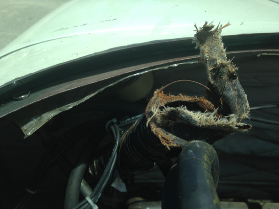
All dead defroster SCAT tubing
I'll need to replace all that...
Started taking the old gages off and thinking about where Im gonna put what.
I'll need to make some plugs for the holes emptied.
Right now, I have analog and half-broken EGT (the selector switch is dead), analog CHT that's not hooked up to anything (wires are butted, and there are no probes installed). Those are going away. HOBBS is also going away. This is all being replaced with CGR-30, so I get a few empty holes and options to move gauges around. I'll probably move the clock and the vac suction gauge so that they're better visible.
Pictures will come later when the work is actually done :)
This last weekend started quite jolly with me putting in the engine grounding straps (didn't have them when I bought the plane).
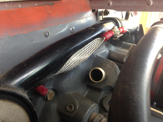
Grounding Strap 1
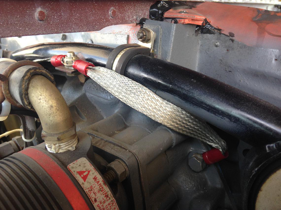
Grounding Strap 2
And then, I decided to deal with something special; the Foot Step. You see, I don't like them. I think they're ugly. So, I decided to remove them, and make a couple of fairings to cover the holes up and to replace the original plastic fairings.
Beej helped me (that means, "did it himself" rather ;) ) whip out the first test fairing.
And then, we needed to take off the steps.
The steps are bolted thru the fuse honeycomb with a couple of backing plates. There are two bolts, top is aluminum one (the thought is that it will shear before the bottom one and therefore prevent leverage and damage to sensitive fuse sidewall honeycomb). I believe AG-5s (later Grummans) replaced them with steel bolts; and people had some serious honeycomb crushing issues because of that.
Aaanyway. The bolts come from the inboard side, thru the streamlined tubing of the footstep and a couple bushings, and fasten themselves to the nutplates riveted to the other side of the footstep. Here's the schematic from the Parts Manual.
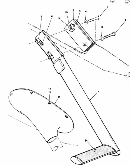
Footstep Schematic
There are a couple more bushings inside the streamlined tubing that aren't shown...
Also, the footstep sits in the wing root. You can kinda get access to the bottom nutplate if you take the fairing off. The top is right in the center of the wing root. And wing roots on Grummans are not fairings. I don't know how to remove one without pulling the whole wing (and Im not quite ready to do that yet...).
So anyway, happy me, I undo the rear seats and the cover that covers all the business under them, take the wrench, "assume the position" and start undoing the bolts. The first thing that happens is the rivets holding nutplates snap off.
So now, I am having Beej, not a small guy at all, under the plane on a creeper, holding the nutplates. We did the bottom one fast, the top one is a pain in the ass because it's, like I said, in the wing root. Had to take the flaps torque tube inspection plate off to get to it, and even then only could hold it with fingers.. the torque tube is getting in the way, you can't get any tools in there.
I should also mention that the bolts sit right under the back seat framing that holds the seat, and I can't even see the bolts I'm undoing without an inspection mirror. Gladly, not much there, so I've found them easily.
So, we undid the bolts.
Hehe. Now, to getting them out...
We were able to tap the bottom bolt out fairly easily. Well, it's right there under the footstep fairing, so that wasn't a problem.
The top bolt is the whole other story...
You see, the bushing inside the streamlined tube is steel. And the bolt is aluminum. The Mother Nature decided to give me a practical lesson on dissimilar metal corrosion.
So Saturday, as this was progressing and it was getting late (and time for Beej to go home), we tried pulling it, rotating it with a ratchet while pushing on the side. No joy.
Beej had to go. We had to disband.
I parked the plane in transient on Beej's field (I couldn't fly back with the footstep dangling like that on one bolt:)); and went home, determined to fix it. Had to have Dash pick me up...
Talked with Ben for over an hour.. Got a lot of good advice. "Heat it up". "Liquid Wrench". "Die Grinder".
Furnished a whole bunch of various tools. Some of them will probably scare some aircraft mechanics :)
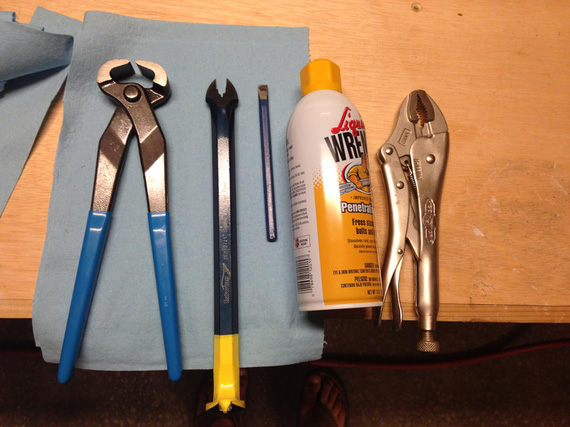
The Tools To Pull That Bolt
Note the pry-bar notch enlarged to take an AN5 bolt. I also custom-beveled the cold chisel to give it a sharper angle (hoping I'll be able to get it under the bolt head).
Sunday.
Put a bunch of Liquid Wrench on that bolt. Tried the chisel - nothing.
Did I mention that I couldn't see the bolt, only feel it? :)
Tried pulling, rotating with Vise Grips - nothing.
Soaked in more Liquid Wrench. Nothing.
Looking at it from the inspection mirror, it was clear that I could cut the head off if I could see it (I would never try that blind. Ever).
So, the mission became the "See The Bolt Head" one.
Bottom interior side panel, if came off, would reveal the bolt from the top and give me access.
Top interior side panel was blocking the bottom interior side panel.
Also, seatbelts and a little latch for the rear seat.
So, off went all of that.
Finally, I saw the sucker!
Tried pulling it out a bit more, now when I had a better access point.. no luck.
Oh well. To The Dremel!
The rest is...
History :)
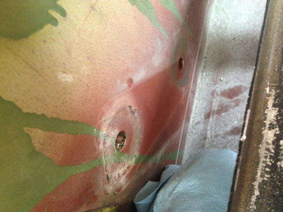
Holes after the bolts were out
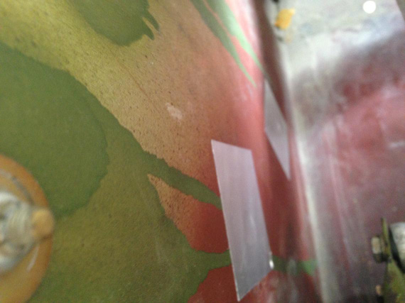
Patched with aluminum tape
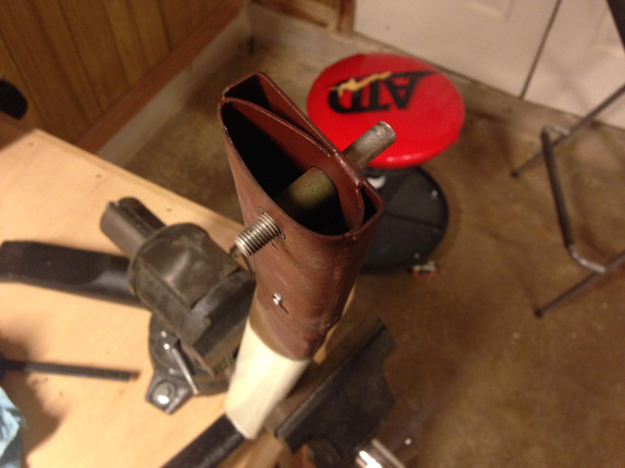
The footstand, with headless bolt shank and the bushing
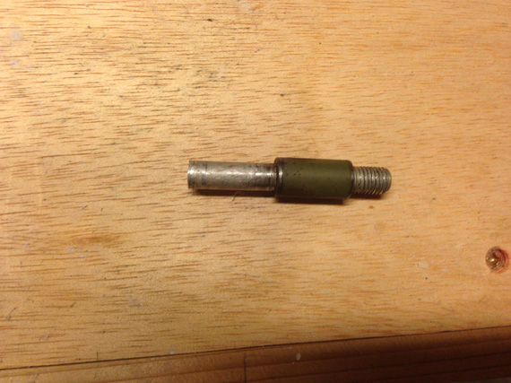
The nasty, nasty bolt shank with the bushing "welded" onto it by corrosion
But the Mother Nature wasn't done with me yet.
Buttoned the plane back up; pulled it in front of the hangar, and took Beej to lunch.
Came back.
Realized that I left the keys to my car in my wife's car parked at a terminal.
Had to walk there and back. A good mile.
Oh, did I mention the 100 degree Texas summer? :)
Coming back, needed to push the plane back. But no - the parking brake on one of the wheels was completely and utterly stuck.
My Cheetah is a 77, and uses mechanical parking brake. Ive heard before that they get stuck; but I always was able to get them unstuck by taking the brake off and tapping on the pedals with my feet.
The way they work is there is a metal plate that has a hole thru which the brake cylinder's piston's shaft goes thru. There's a chain that pulls it up, making it eccentric with the shaft, which locks the shaft in place.
Well; apparently it got a little more hot while we ate, and that plate just didn't want to go down. Tapping the pedals while putting the brakes on and off didn't do anything.
Oh, did I mention that I would have fiddle with it, get out, try to push the plane back, fail, get back in, all in a 100 degree weather? Not fun.
Finally, gave up and "assumed the position" again. That's when you dive backwards under the panel with feet hanging out of the airplane.
Wiggling it for a minute or so finally yielded a loud snap, and it was unstuck.
Phew.
Flight back home was uneventful :).
Bonus pictures:
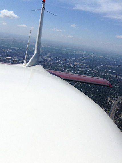
In flight, looking back over Downtown Austin (I risked my phone taking that!)
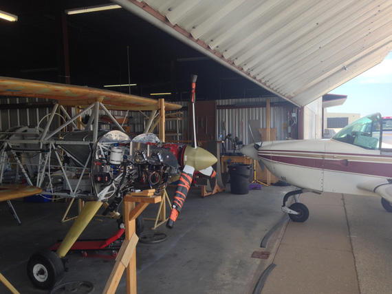
Skybolt: "Are you talking to me!?" Cheetah: "No, are you talking to me?!!!"
Lack of planning on your part does not constitute an emergency on mine.
© Copyright "79FT". All rights reserved. Feel free to cite, but link back to the pages cited.
This website only shows how I did things in my various projects. These pages are for information and personal entertainment only and not to be construed as the only way, or even the perceived correct way of doing things. You are responsible for your own safety and techniques.