[79FT]: Building Things |
 |
Strobe Shields for Cheetah
... fun with stretcher
| On: | Oct 24, 2014 |
| In: | [Misc] Cheetah |
| Tags: | 9891U, mechanicing, sheet metal |
No Skybolt news, you say?
Well, with dead alternator, tons of work, and unfinished install of a gauge that is supposed to keep you informed about your engine, not much time for the Bolt.
Oh well.
I love to fly at night. It's just something out of a different world, something... else.
There are a few things that are extremely important at night. Most importantly, the old "See and be seen" rule.
To be seen, you need blinking lights on your airplane, nav lights, ideally a landing light, and such.
To see, you need to retain your night vision. That means, no bright white or any color light besides something like red or blue. Otherwise, your eyes readjust for "daylight", and you are at good odds of not seeing other blinking lights... like the ones on an airplane you might fly into!
You see, I don't have strobe shields on my plane. Take a look at the picture below, and imagine you sitting in the cabin.

Strobe Shields on a Grumman
You see that vertical little metal "fin" I circled? That's what blocks you from seeing the strobe - a bright flashing white light. If that metal fin is not there, you basically get blinded every second or so.
It's so bad I ended up flying with strobes turned off a couple times I was up after dark. I figured, just one beacon on the tail and no strobes is better than a blind pilot.
And especially now, when the weather in Texas is so nice and night flying is just calling and calling and calling, that became a priority project.
So, on to it!
Those shields go under the wing tip light cluster lens, and the spot they're supposed to go into is curved. Shields themselves are nothing but a curved L - angle out of aluminum.
So, I needed a stretcher.
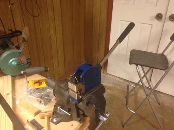
The Stretcher
Prepared one of the wingtips:
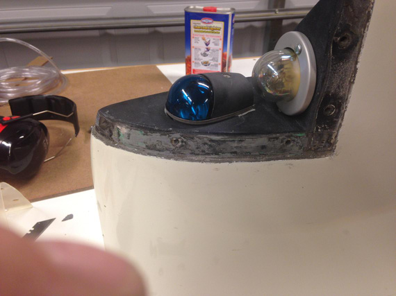
Wingtip light cluster with the spot where the shield goes cleaned up.
First, I decided to make a test piece to get some practice. Never used a stretcher before.
We start with a simple L-angle. I used 6061-T4, 0.025 thick.
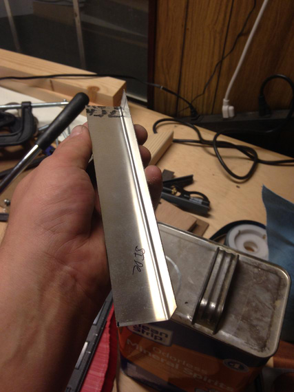
Simple angle
And then, stretch-check-stretch-check... Not bad at all. Just takes time.
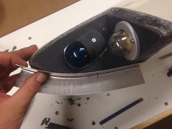
Stretching
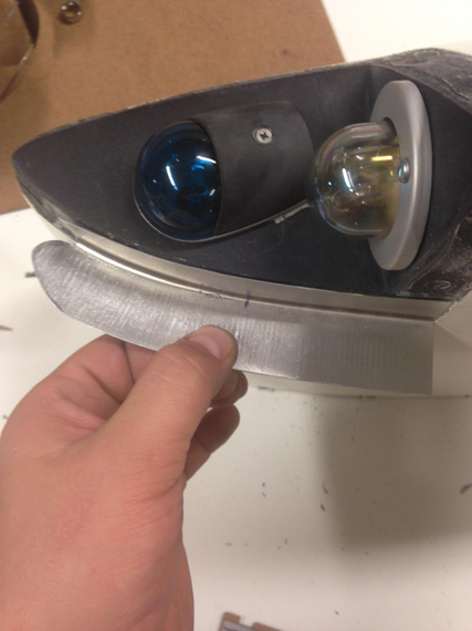
Close enough for a prototype.
You can see on the pictures that the stretcher leaves pretty deep "scratches". On the prototype, I tried sanding them out -- only to get my metal turn paper thin.
On the real one, I decided to fill them up with Bondo.
So, bought some, and made myself a pattern too -- which I printed full size.
To do that, asked Adam, the guy who bought my 28797's share (thanks again, man!) to take some pictures of strobe shield on his Tiger.
And then, just drew around it in Solid Works. Turned out nice.
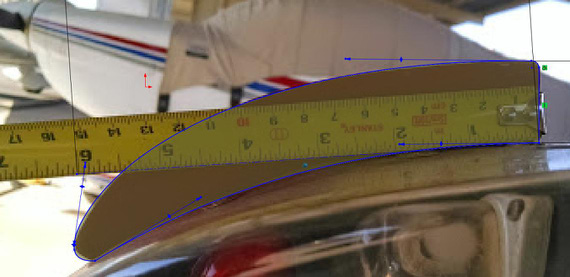
Sketching around the photo in SWX.
Note the tape measure above -- I first drew a line 6 inches long and scaled the photo until that line matched 6 inches on the tape measure. This way I ensured proper scale.
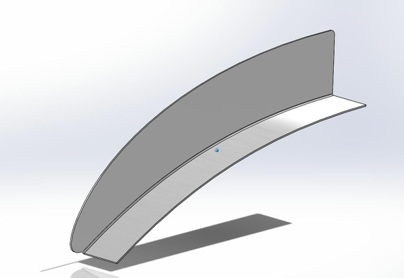
SolidWorks part for the Strobe Shield
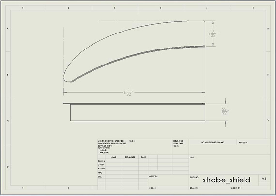
Drawing of the part for the patterns.
So with those patterns printed out, I went to town.
First thing I noticed is that curvature on the wingtip I was working on doesn't match the pattern :). Of course. They're all different (and by the way, on the other wingtip it matched perfectly. Go figure.). I wanted the pattern to primarily get the general shape right.
So, here I am stretching my L shaped angle, and... SNAP!
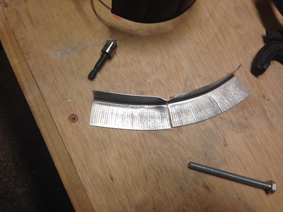
:(
So now, bend another L angle, deburr, clean up, size... sigh.. I went much much slower...
I think, getting it perfect took around 3 hours of careful work. That curve gets aggressive towards the end. And, when I was almost done.. snap! I tore it up again, this time the very tip.
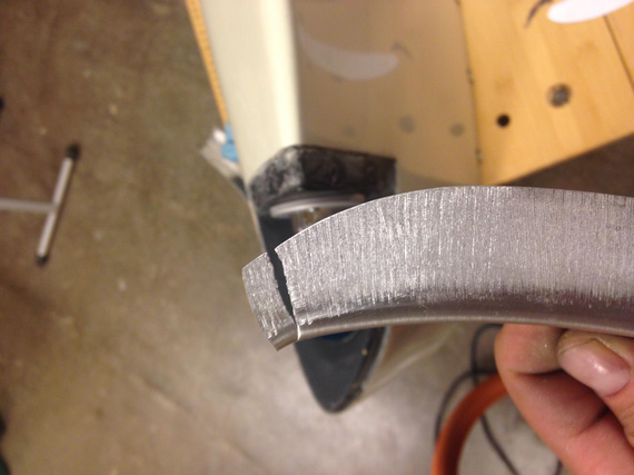
Damn!
Luckily, it actually still was long enough (I started with a piece longer than necessary), so I was able to get away with this tear. Phew.
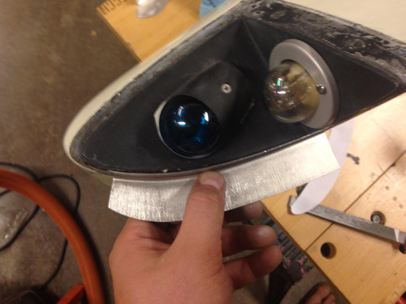
Perfect fit!
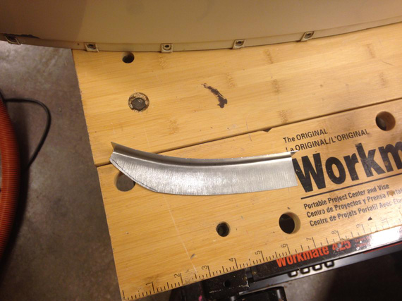
Cut to about the right size
Next, came a lot of sanding, filing, and emery-clothing to get it to the right shape. And then, the holes.
Those had to be duplicated and match up with the existing holes in the wingtip, so I made a simple hole duplicator. No, I'm not paying 10 bucks for that thing!
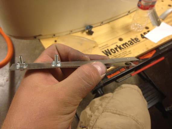
Homemade Hole Duplicator
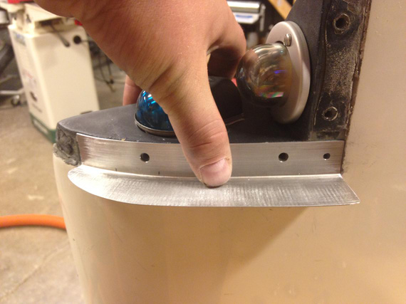
And, we have the holes.
Finally, I filled all the scratch marks with Bondo, sanded it down, and called it a nite. I think it was around 3 am then :).
Next day, the other wingtip.
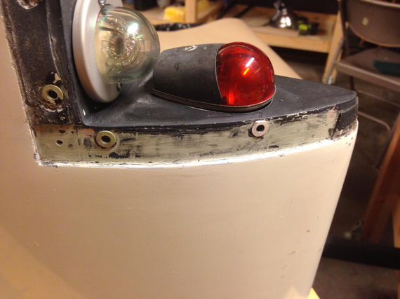
Prep
Notice that this one has rivnuts and not just holes. I now have a theory why this plane is missing strobe shields.
I think the guy who tore all the threads in the fiberglass wingtip and installed those rivnuts (remember, the other one doesn't have them?), was too lazy and didn't want to tweak the holes in the strobe shields to match with the rivnuts. That's my guess.
Initially, I thought about making oversized holes in the shield, but that would put one of them too close to the edge. Then, I tried filing the rivnut down a bit, but decided that I'm not gaining much there, and that notching the strobe shield base would be best. That's what I ended up doing.
I made just the first notch, and to stretching it was!
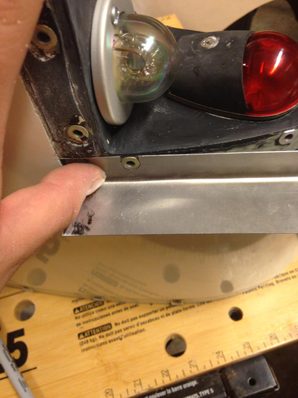
First Notch
When it was close to the other rivnut, I notched area around it.
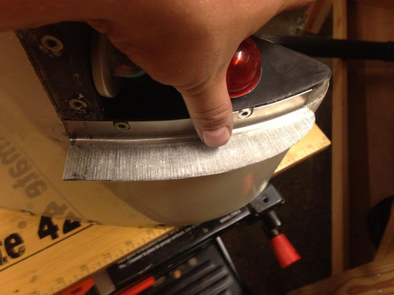
Secont Notch - close!
They came out perfect.
And then, tons of filing, shaping, sanding, Bondoing, sanding, washing, and...
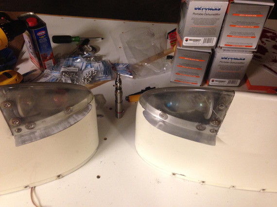
All done!
They're not quite complete yet. I'll have to clean up the rest of black tape from under the wingtip lenses and replace them with new ones, but that'll come after painting the shields. I'll ask Dave Fletcher to paint them into the same Imron he's gonna use for the (now soon to come) wheelpants.
And you know what.. that was fun!
If God had intended man to fly he would have given him enough money for a Bonanza.
Up ↑
Banging Sheet Metal
making bulges
| On: | Sep 03, 2014 |
| In: | [Misc] Cheetah |
| Tags: | sheet metal, cgr30, mechanicing, 9891U |
So on the Cheetah side, I am slowly ramping up for replacing all the engine gauges that I currently have on the panel with the CGR-30. I got it at Oshkosh, and finally, the box arrived a couple weeks ago.
Ain't she a beauty? Assembled on the bench for testing and familiarizing myself with it :)
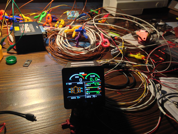
Ain't she a beauty?
Because of it, I will lose a few 2 1/4 inch round gauges, and I decided to make some covers for the panel, not to have unsightly holes in it.
Of course I could've bought them from Spruce or whatever, 5 bucks a pop, but if you know me, I would rather spend hours making something I can make. Besides, this is a nice first sheet metal exercise :). And, I wanted a nice domed bulge on each one of them. Just Flat wasn't enough.
So, I got to it.
First iteration was making a jig that would sandwich the sheet between two boards, with holes over and under the metal. Then, I would press a "piston" thru the holes using my vice as a press. Pictures are better than a thousand words.
Three piece jig + soon-to-be-'piston'. Oak boards sandwich the sheet between them. Ply plate has the "piston" and is used as a backing plate for it.
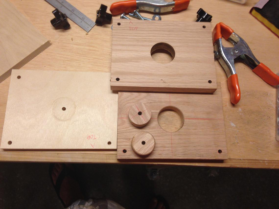
Jig pieces
That didn't work out. Vice jaws are not perfectly parallel, and the "piston" is not exactly the same diameter as the holes -- so it gets misaligned, even though there are four guiding bolts in the corners... Here's the jig assembled, and one of the first tries.
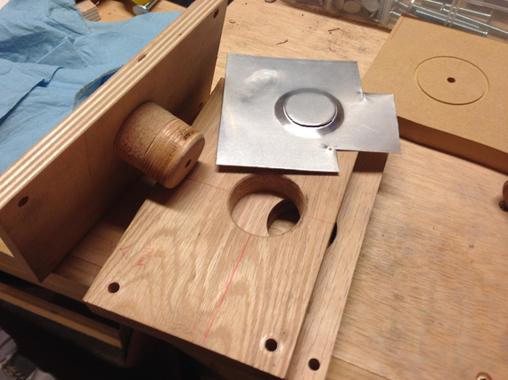
First try...
I think I tried it two or three times, with the same result.. no matter how much I tried to align the "piston", it would make a bit more pressure on one side of the jig than on the other, either resulting in a tear, or in an uneven "bulge".
Out of desperation, I took a piece of metal, laid it over one of the holes in the oak jig board, and started banging away - and was surprised! I was getting almost what I wanted, just not clean enough.
I tried sandwiching the metal between two plates and banging via the top hole - and made a fairly nice bulge! The edges weren't very clean, but I reasoned that if I opened the top hole up a bit more, that would give me access to the edge, and I will be able to bang on the edge a bit more, defining it better.
Ha! No. Same stuff.. I was able to make a fairly nice bulge, but the edge will be all "torn" and ugly.
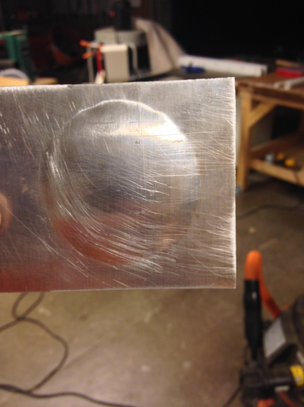
Bulge is there, but the edge is god awful
I also tried putting a profile on the bottom, "die" plate of the jig, with a very sharp edge and curvature under it.
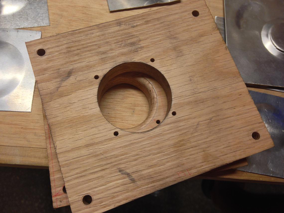
Second jig
No luck. I think I spent a couple hours, making over ten "bulges" and trying different hammering techniques...
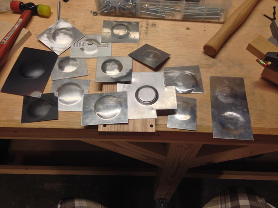
All those tries.
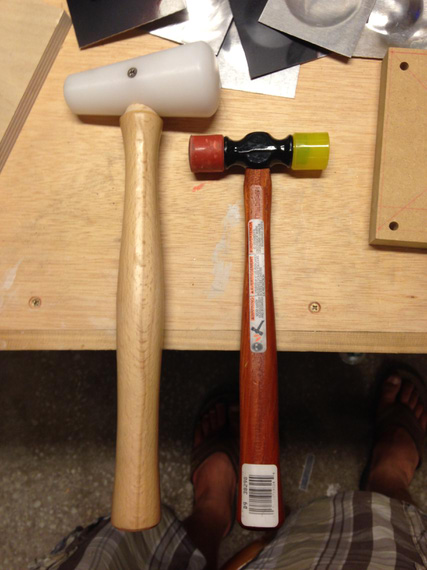
The Two Hammers
So I gave up, and emailed Bill Rose, the gentleman who gave me all the SolidWorks parts for standard HW, and, in general, helps me a bunch with my silly SWX and other questions, for advice.
Bill suggested using MDF for the jig instead of oak. Apparently, irregularities in wood grain would make it hard to define the edges uniformely. He also suggested using corking tools akin a big "chisel" on the edges to better define them.
..and.. it worked!
The third jig is ugly, but it works. Upper hole is enlarged just to get access to the edges (I didn't bother making the top hole concentric with the bottom or even round; there was no need).
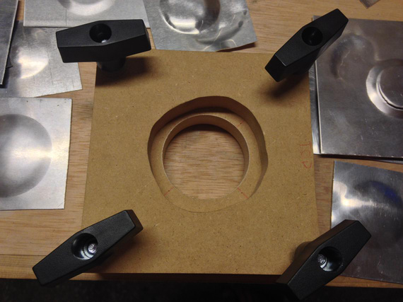
The third jig
I used the two-headed plastic/rubber hammer's rubber head as a corking tool, lightly hitting it with the plastic mallet, and having it slide from the edge into the center of the bulge.
This bulge still has some "orange peel" on it and needs to be smoothed out, but the edges are very well defined!
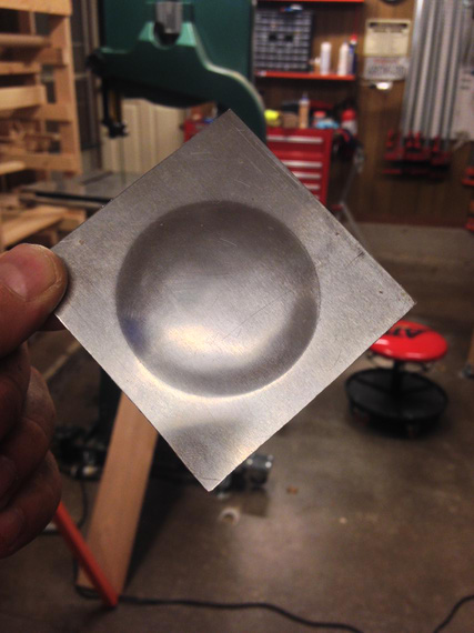
Check out those edges!
But of course, I screwed up again - the hole in the bottom, "die" plate of the jig, is of a wrong diameter (I used the wrong holesaw). But hey, at least I think I figured that technique out!
Good evening in the shop tonight :).
Why did God invent women when airplanes were so much fun?
© Copyright "79FT". All rights reserved. Feel free to cite, but link back to the pages cited.
This website only shows how I did things in my various projects. These pages are for information and personal entertainment only and not to be construed as the only way, or even the perceived correct way of doing things. You are responsible for your own safety and techniques.