[79FT]: Building Things |
 |
Baffle Seals
...are baffling!
| On: | Mar 13, 2021 |
| In: | [Chickenhouse Charger] Electrical Rebuild |
| Time logged: | 20.5 |
| Tags: | 6781G, MA5 Charger, FWF, baffles, engine |
One last thing identifiable as a "sub-project" left! Also, the most annoying thing probably.
Baffle seals.
The old ones were cruddy, petrified, and worn. In fact, baffles were what I was working on when I discovered that I needed to rebuild the electrical.
So I guess it made sense to finish where I started.
I pulled the old ones out of their bag, looked thru my notes of what goes where, and put them back up.
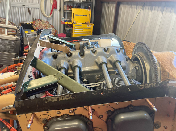
Old baffle seals back on
And then, duplicating and tweaking.
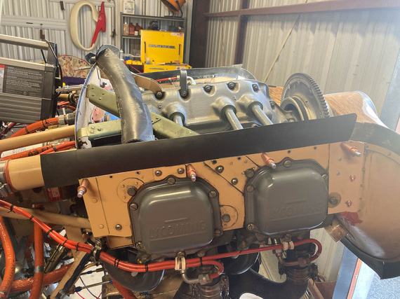
New seal fitting
Weirdness number one - or rather, unusualness? - was how Remo hooked up the nosebowl. On most airplanes (and on the plans as well!) the nosebowl is just held by the rest of the cowling.
On this Charger, Remo decided to hold it on four U-channels bent out of aluminum going from the firewall to the nosebowl. Those U-channels would also act as cowl stiffeners.
Here's one of them, on top of the engine baffle.
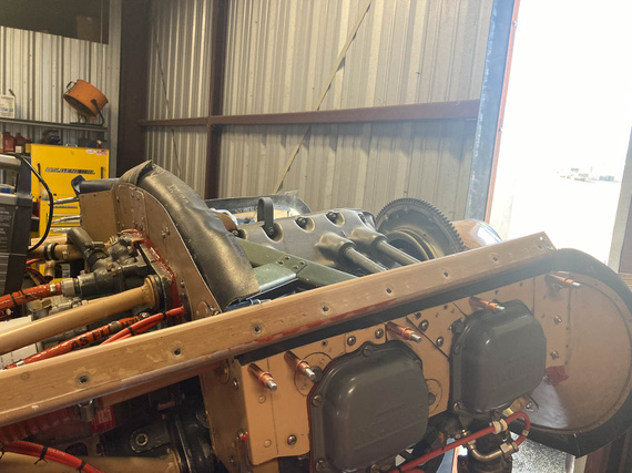
Hosebowl support C-channel
I even think I know why. He probably attached the nosebowl to the flywheel with some kind of a jig, lined everything up the way he liked, and made those.. stringers? I'll call them stringers. In place. That held the nosebowl, and he could build the rest of the cowling around them.
Problem?
Well, the two on the top have to go "thru" the "airbox" that's created between the motor and the top cowl, making two nice holes in it - and allowing air to escape thru them rather than be forced down thru the cylinders.
Here you are looking towards the firewall thru one of those hose.
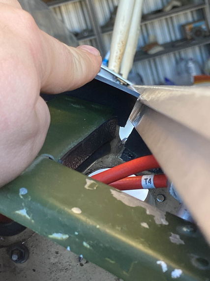
Hole
I pondered this for a while, asking Mr. D. if on his Eagle he built he had anything like that. He said no; his cowling was "normal". No "stringers". I thought about making some small strips and attaching them to the "stringers" to plug these holes. I thought about maybe filling them with RTV (making those stringers' removal a fun affair).
At the end, decided that for now, I am going to ignore it. There are much larger "takeoff" holes right there - for the oil cooler on one side, and for the fuel pump on the other. So, there.
The other problem was that instead of using standard 1/8" large-head pop rivets almost everyone uses to attach the seals, Remo decided to be "frugal" (weight savings?) and used 3/32" rivets on the back baffle. He used 1/8 rivets on the side baffles alright; but instead of using large-heads, he drilled the holes too close to the edge and used a "retaining strip" - basically, a narrow piece of aluminum on the "rubber side" that acted as one long washer.
That's all good, but of course they were old, torn to pieces due to vibration, and basically all broke up when I removed the old baffles.
I toyed with the idea of using large head rivets or emulating them with washers.
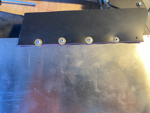
Large head rivets emulated with washers.
Talking to Mr. J.F., one of the IAs on the field, he seemed fine with that. Mr. D of that Eagle fame said it was a good idea too. Mr. J.F. said, "baffles are baffling", by which unwillingly contributed to the subtitle of this rant.
In the end, I ended up remaking the retaining strips.
Why?
Because the holes were too close to the edge. A larger diameter rivet or washer will "poke in" to the seal when it bends down, and quickly cut a slot in it. The seal will tear up, and.. well, that's the end of that seal.
So, the strips.
Using old ones as templates to replicate was out of the question - they were too beat up. So, the second best option? Make them in place.
First, the holes.
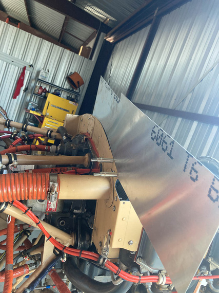
Drilling holes to match
Then, I would draw the edge onto the metal and take it off...
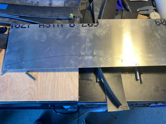
Top edge duplicated
... cut it, and put it back on to make sure the edges would match up
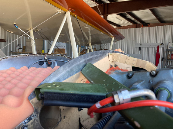
Test fit
The bottom edge would be duplicated off of the top edge using a compass, and - voila:
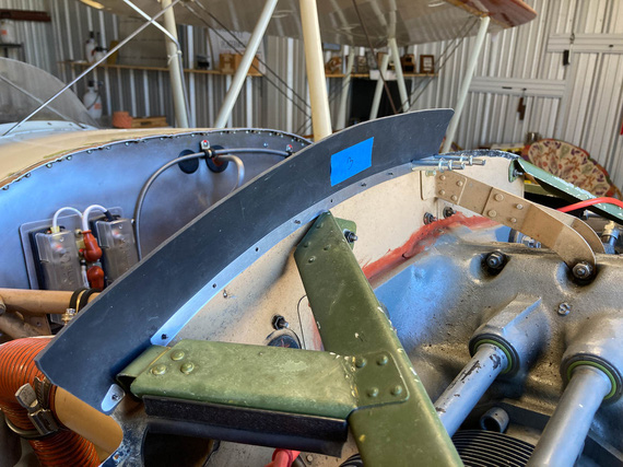
The new strip
The strip would be done.
And that, all around.
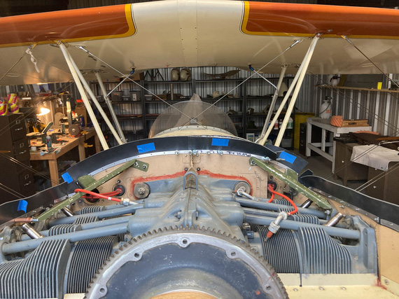
New retaining strips
Final test would be making sure it fit with the cowling - didn't pinch anything anywhere...
Except that...
Funny story. The top piece of the cowling was standing upright (grave mistake!) on the top of a shelf in the back of the hangar. For a year, or probably even more.
And then, one day, it did catch a particular gust of wind that so rudely entered the premises, couldn't stand the offense, and fell down.
WHACK! I heard.
First thought: "Please, not on the airplane!". No, it didn't fall on the airplane.
But it did mess itself up.
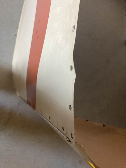
Bent cowl
So I guess I learned my lesson at not to steep a price.
Mr. M, the same Mr. M that welded my exhaust tailpipe back on made quick work of it with his very fancy shrinker.
The cowling went on, and I confirmed that everything would fit - because next, the seals would be riveted permanently.
Then, Mr. M decided to join me. He'd pull a Cleco, and I'd pop a rivet...
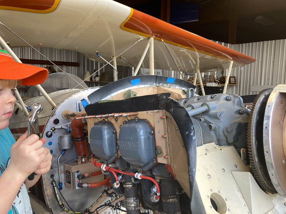
Riveting
...and, we were all done!
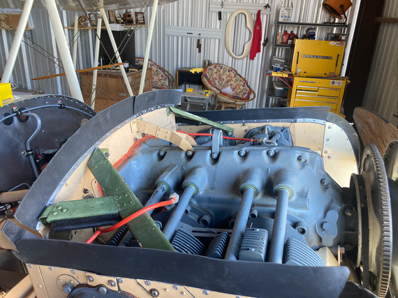
Done
Some final passes with RTV to patch up some holes between the metal and the motor, and I call this good to go.
CAUTION: Aviation may be hazardous to your wealth.
Up ↑
Oil Cooler and Hoses
...mainly, fiddling
| On: | Mar 12, 2021 |
| In: | [Chickenhouse Charger] Electrical Rebuild |
| Time logged: | 6.9 |
| Tags: | 6781G, MA5 Charger, FWF, engine |
After my first run, one of the things that I quickly discovered was that the oil cooler hoses leaked from behind the hose ends.
Of course; the only two engine hoses I have not replaced must leak. That's just Murphy's law.
And of course, since I was messing with it, I had to tweak it to my liking, and I am glad I did.
I wanted to replace these two fittings.
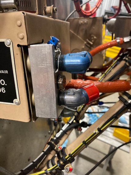
Oil cooler inlet and outlet
They were both aluminum, and one of them was scratched - I didn't like that; and I like steel fittings on thinks like this. Plus, the hoses are long and heavy. I'd feel better.
So the oil cooler had to come off, so that I could take off that aluminum.. "manifold"? block off of it, stick it into a vice, and undo the fittings.
Ha!
To do that, I had to remove the shroud... attached with screws, some of which I very conveniently blocked access to with my new brake line I relocated.
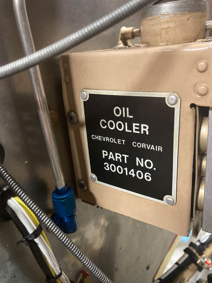
Oil cooler fastners: blocked off
Well, shucks.
Custom ground and shortened Phillips bit was in order, and that helped me undo the screws.
Then, the manifold block came off.
You can see in the first picture above that the block is held to the cooler with a large bolt - going thru the cooler, with it's nut on the other side. There must be some kind of sealing between the cooler and the block, right?
Well,
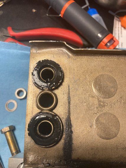
Seals that were
Yeah.
Now, this is a Corvair cooler - and I learned that they interface to the motor on the original car using these rubber donuts - but these seals looked nothing like Corvair's. They instead were these weird step-washers - one side interfacing to the surface of the oil cooler, and the other - to the grooves machined in the manifold block
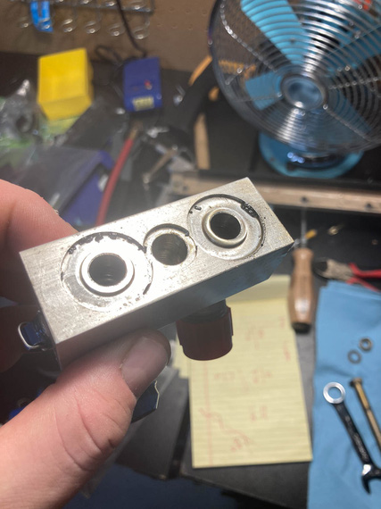
Seals interface on the manifold
What probably happened is Remo, or whomever installed this cooler, had some seals lying around, machined the block to fit them, and called it a day.
Trying to find these yielded no results - but I got an idea.
O-Rings. If I found the o-rings of just the right size and thickness such that they would be just a bit bigger than the distance between sealing surfaces, screwing the manifold block back to the oil cooler would squish them tight, and they will hold the pressure just fine.
Here's the idea.
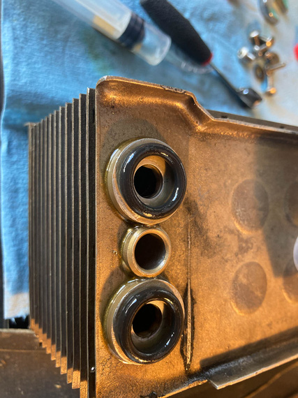
O-rings as seals
These were a bit too big, but the next size smaller worked out. I wrote it down for the future (but I do have a bag of like a hundred of them, too). Made sure the temp spec on them was in the range, too, and that they were okay to use with engine oil.
Meanwhile, also cleaned up all the ragged edges, cleaned up the threads inside the manifold, got a couple of new steel fittings, and a couple hoses from Tim at TS FlightLines.
The rest of putting the thing together was a non-event. Oh, and I ended up using hex-head screws for the side where access was blocked off by that brake line - so that they could be tightened with an open end wrench.
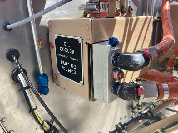
All done
Test run, no leaks found.
Jet noise: The sound of freedom.
Up ↑
Exhaust Clamps
...shucks!
| On: | Oct 16, 2020 |
| In: | [Chickenhouse Charger] Electrical Rebuild |
| Time logged: | 9.0 |
| Tags: | 6781G, MA5 Charger, FWF, engine, exhaust |
About a week after engine start (yep, I took a break), back at the airport, and looking over the motor again, trying to figure out what the hell was that electrical type smell...
One theory formed...
You see, I hung the exhaust with copious amounts of anti-seize. I do have either a Grumman or a Cessna style exhaust, with 4 "stubs" (aka risers) coming off of the motor, and a "spider" looking setup hooking to them, joining all cylinders into a muffler under the front of the motor.
Risers go inside the main exhaust, and are held by clamps, engaging "beads" on the pipes.
So I thought, I'd hang the whole thing "loosely", so that individual cylinders will move, and use high-temp anti-seize to make sure it, well, doesn't seize up.
The working theory was that that anti-seize was "cooking" and produced a smell. I saw a lot of it blown out from around the clamps.
Another working theory was that maybe there was an insect or few stuck around the baffles or cylinders somewhere. There was one big wasp in there that I saw after the engine start - and smoldering insect carcasses sometimes smells just like burning wiring.
I know that last bit, because I spent insane amount of time, and got aggravated to no end, when I got this weird electrical burning smell in my old house. I was convinced I hit a wire when hanging some stuff to the studs just a few days before, and I literally drilled holes along every place where I hung things with a hole saw to make sure there were no wires.
There was one, but it wasn't pinched or damaged.
And all that was finally traced to a roach that died inside my air conditioner heat exchanger, right on a heat strip - heating season just started, the roach was dead and smoldering, and the AC was blowing that lovely smell all over the house. I later read a lot of fire department stories about similar situations of people freaking out and thinking their houses were on fire.
At any rate. My theory was either the wasp, or the anti-seize.
And my anti-seize blew out of the joints real well (ha!) - sooo.. I guess, the loose hanging exhaust idea was a no go.
And, by the way.
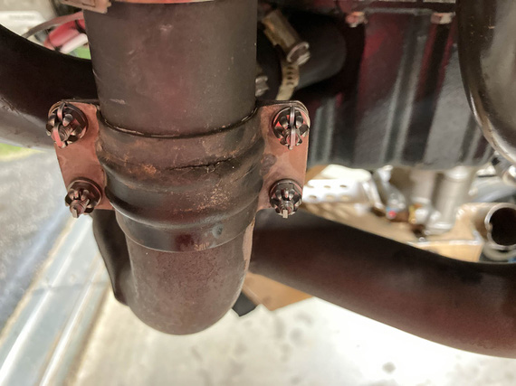
Crack!
Damn.
So the exhaust was taken off, again.
After quite some researching, here's what I found.
I had 1 3/4 risers.
Those clamps are ubiquitous Cessna clamps. Part number irrelevant - because...
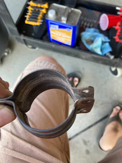
Cessna clamps
Grumman also has 1 3/4 risers.
I was convinced I had a Grumman exhaust, because hey, what'd you take: a Cessna or a Grumman? :)
Those clamps are impossible to make to not leak. Forums confirmed by the way. Mr. John F. confirmed, too. Just think about them for a second - they will leak.
Grumman clamps are a bit different - they have this "liner" that is supposed to act as a gasket.
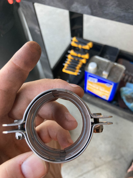
Grumman clamp
Yep, you guessed. I went Grumman. I don't have any Cessna friends. I have a ton of Grumman friends. You know where my heart lies.
Grumman book does not state anything about hanging the exhaust "loosely". It states to use Walker AcoustiSeal <part number here that doesn't exist anymore> (of course).
Mr. David Fletcher of Fletchair by the way confirmed that the exhaust needs to be tightened down, and that it's not a usual problem with it cracking due to differential movement of cylinder heads. Or rather, of course it will crack. But not all the time - it's perfectly fine.
We spent quite some time with Ben, figuring out the clamps (I was initially reluctant to fully close them because of the liner deforming too much), and AcoustiSeal. He helped find a catalogue AcoustiSeal with a different part number - 35959 - that is definitely within the temp range. I decided to use that instead of anti-seize. Researching a bit, it seems to "burn up" and "ash out" forming a fluffy, powdery type seal.
Cleaned every pipe, put on the new clamps with AcoustiSeal, and tightened them down. That was bad. Really bad. Torque was definitely excessive to close them, but I had to close them. It's obvious why, too - the OD of the pipe is 1 3/4; the ID of the clamp is 1 3/4, but the thickness of the steel liner is about 1/64 - so yeah. And my pipes aren't perfectly round, or smooth, either.
But they did close, and they did fine in the end.
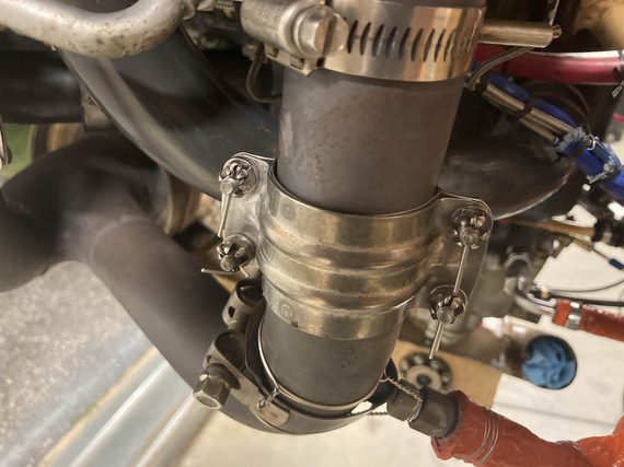
New clamps
I decided to try them. Worst case, I'd go back to Cessna style.
Also, cleaned up around the smoke oil injectors, and put AcoustiSeal there too. You can see one on the picture above. Re-safetied them a bit better too - the idea Glenn had was that if the main worm clamp failed, the safety wire will at least hold them in place.
And then, the other question came up that we spent quite a bit of time arguing over with Ben.
What's the torque on the Lycoming exhaust nuts?
It's not listed. Stud driving torque is listed. It's listed for vertical and geared motors in relevant sections of SSP-1776 at 160-180. Grumman book lists them at .. 110-140 if I recall correctly. The "by the book" application of "default torque unless otherwise noted" section of the "Direct Drive Engine" part would put it at 204-228. All inch pounds. So the range, depending on the source, would be 110-228 - a 100% difference. !!!
A lot of folks on the internet use the "default" - 204-228. A few were told to do so by Lycoming. When I torqued them, it felt... somewhat excessive, given that there's a gasket in play there too. There's no straight answer, really.
I settled on 180. Why? Grumman's book assumes "beaded" - not "no-blow" - gaskets. 180 is much closer to 204. 12% difference - within margin of error of a crappy typical torque wrench. And if mine is reading "high", I'll still be in the range listed for geared and vertical motors - which have the same cylinders as far as I know.
Yep, convoluted.
Anyway, second run yielded a very different smell - this time, of the regular "burning oil" sensation (which is typical for a motor that slowly weeps oil and throws it everywhere when shaking - that's the built in feature of spray lubrication and corrosion protection of your motor compartment! What? You weren't aware of that?!).
Much better. No blowouts of sealant anymore. No exhaust leaks I could discern.
... and, an oily fitting that I thought was oily after the first run because we used it to pour oil into the oil pump - but no, I confirmed a hose leak around the fitting of the only two hoses (oil cooler supply and return) I did not change.
Le sigh.
"Listen up gentlemen, or something's gonna happen that none of us wants to see. Besides that, you're (tickin') me off!"
-ORD ATC
Up ↑
Motor Start
...:)
| On: | Oct 15, 2020 |
| In: | [Chickenhouse Charger] Electrical Rebuild |
| Time logged: | 23.0 |
| Tags: | 6781G, MA5 Charger, FWF, electrical, engine, exhaust, alternator, fabrication |
And so, we're onto the race to the first motor run. I am writing this about a month later - according to the log, the motor was started up September 19, 2020.
But first...
Upfront
Finish mounting the starter was no problem: clean up the threads, clean up the studs, torque, done. Then, the alternator.
Belt tensioning... too annoying by hand, but it took me a while to stop trying and become sensible.
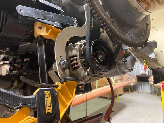
Belt Tensioning
You gotta safety two bolts over there, and I decided to make it nice: for the bottom (pivot) bolt, drilled a tiny hole in the bracket lower than where the alternator would be, and for the top bolt attaching the bracket to the motor... hmmm...
Somewhere on VansAirforce someone used a cherry rivet as a "hookup" point for the safety wire. I thought to one-up that, and use a short #8 screw - drilling it's head.
Frankly, I didn't think it'd work out.
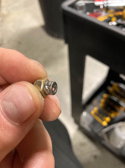
Drilled cap head
...but as you can see, it did.
So then, to the hole in the bracket. I needed a #8-32 tap.
Side, fun, story: quite a while ago I ended up bidding in a machine shop liquidation auction. Got quite a few nice things, including a very heavy duty bandsaw - and, accidentally, a massive cabinet full of tooling. Anything you could imagine: inserts, drills, taps, slitting saws, you name it. In all shapes and sizes. When we moved the cabinet, we emptied it into about 10 boxes, so ... I did have a #8-32 tap. In fact, probably about 20 of them. Question was, which one of the boxes were they in.
... apparently, in the one on the top. Hmm. This kind of luck is unusual.
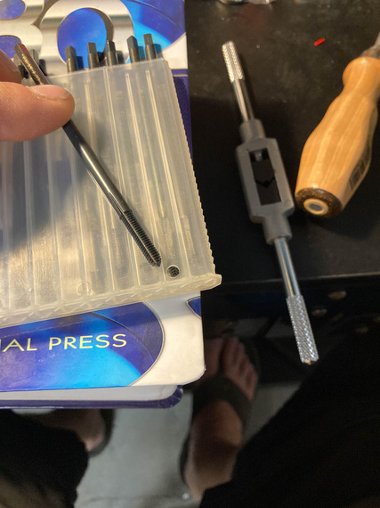
Tap
Look at it carefully. Does it look like a regular tap we are all used to?
Didn't to me either.
So to researching we went.
Aha! "Threadforming" tap. AKA "Cold Rolling". So that's how they're done. Rolled threads are formed into the metal rather than cut; giving them superior strength. Basically, the tap shapes the metal, displacing it in the valleys and raising peaks.
Company that made these taps was advertising them for CNC milling. Well, what's a human if not a bio-CNC machine?!
Okay, problem number 2. I was pretty sure normal tap and drill chart values for hole diameters won't work; making too small a hole. Hmm...
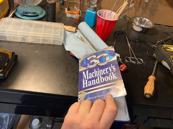
The Bible
Aha! "Ideal Theoretical Hole", and closest drill available charts are just what's needed.
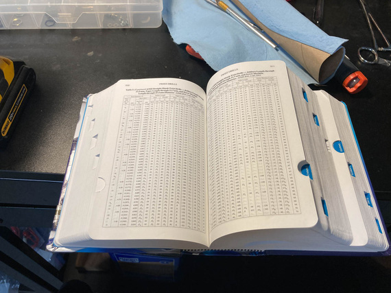
The Word
And with that, the affair was a non-event.
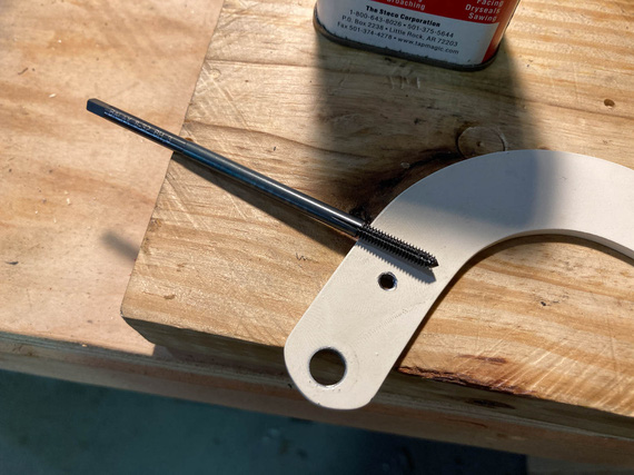
The Hole
Actually safetying was annoying - I had to try twice, because I had to use a hand-twister and you had to get the length just right.
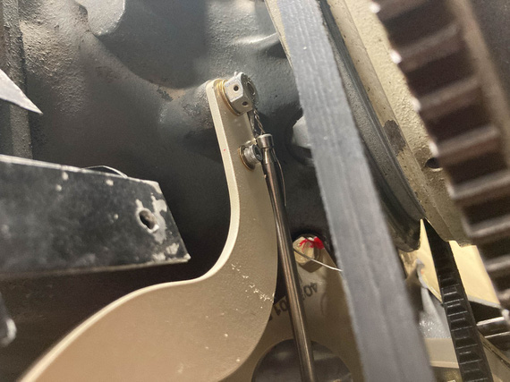
Hand Twister
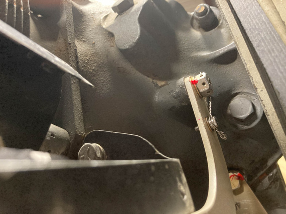
Safetied!
Airbox
That thing needed to be put back on, and carb final torqued with a new gasket. Cleaned it all up inside as much as I could, and had to cut a couple of special gaskets that I can't for the love of me figure out where to get (carb's base is different size from the top - and this is an "airframe" problem - read, "no standard part from Marvel or Lycoming I could find reasonably"). No problem. Used the same material Lycoming used for their gaskets, ordered from McMaster, and made me a couple.
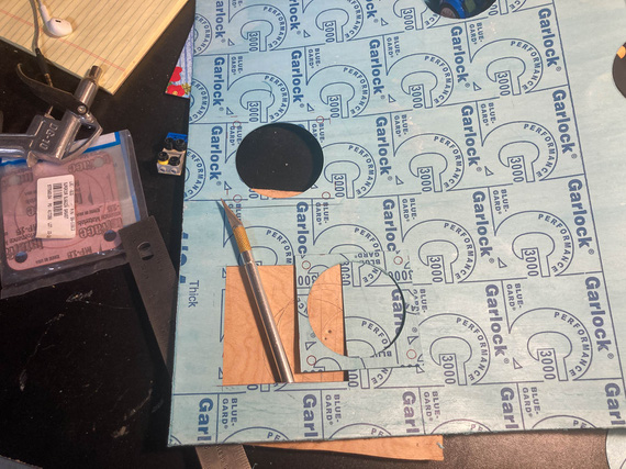
Cutting gaskets
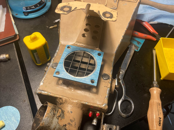
Where they go
Perceptive will see the "airflow straightener". Glenn had it on when he put on the Rotec TBI, and in the times of my research of TBIs, I have discovered that some folks claimed they helped on carbureted motors as well. Well, it definitely won't hurt - aside from my having to do two gaskets instead of one. No biggie.
Carb
One interesting thing that happened. I had to drain the carb bowl of all the preservative oil, and flush it, so I took off the plug, drained it, and started putting it back in. Plug's an NPT thread with torque listed by Lycoming in SSP-1776 at 144 inch pounds.
Hmmm.. I noticed it was going in way deeper than it was in before, and way "harder" than when I took it out.
Hmmm.. Well, it's Lycoming, they know what the hell they're talking about. So in it went, at 144 inch/lbs.
But this bugged me. I think some other day I pulled out the Marvel's manual. 25-30 inch/lbs?! WHAT?!
Back to Lycoming. 144. Marvel (the makers of the carb)? 25-30. Damn it. Forums? Nothing interesting.
I finally figured it out. In SSP-1776, in the table for special torques, Lycoming lists the plug to have 3/4 pipe threads. Mine were 1/8 NPT. Lycoming's torque for those is 40-44 inch/lbs. Still higher than Marvel, but much closer now.
So, I undid the plug, that cut a bit of the tapered thread "deeper", of course. And put it back in, with the right torque this time.
Other Stuff
And then, minor stuff here and there. Cleaned and prepped spark plugs. Put the exhaust back on. Tightened things that had to be tightened. Charged batteries. Tied up everything hanging loose. Gave the plane a good look all over.
We were ready for the final day. There were a number of things I needed two sets of hands for, and I had just the man lined up.
Day X - or, September 19, to be Precise.
My buddy Mr. N. agreed to help, and be my observer and fireman (just in case). Mr. M. was extremely inquisitive about how we're gonna be putting out a burning airplane, and I had to explain a number of times that the goal of an exercise of starting a motor that's been idle for a year is not to have it go ablaze, and having a fire watch nearby is a part of prudence, not expectations. He seemed to have been disappointed. I would be too, if I was 5.
So, on a nice Saturday, we went to the airport.
First, drained all the pickling oil. Took off the prop (because we'd have to spin the motor to pressurize the oil lines). Put the fuel pump back on. Tightened all new fuel lines, and leak checked them. Mr. M. used my fancy "button with alligator clips" to turn it on. Put new oil in, primed the oil cooler and pump (and this is fun in this airplane, because there's no oil filler neck on the motor). Checked control cable travel, and final cotter pinned them. Checked brakes again (though we bled them when I finished fixing them up).
Then, came the pressurization, and purging of oil lines, time. Mr. M insisted that he wants to "press the button" - which would put +12V onto the starter contactor; bypassing my normal starting circuit (latter would make the left mag hot, and I didn't want that).
I told him to press the button and hold it and not let go till I told him to.
Now, starters with a motor with removed spark plugs are fast, loud, and annoyingly sounding. Mr. M. pressed the button. Jumped a bit. Grimaced a bit. He clearly didn't expect it. I didn't see it, Nick told me afterwards - I was watching the oil line. I yelled "Stop" when I saw the oil come out, and looked at Mr. M - who, at that point, was shaking and at the point of breaking down in tears. But! He didn't let go of the damn button. Man.

Mr. M
And that was that. Plugs went in, and we were ready, but broke for lunch, first. Mr M deserved his hot dog.
... back from lunch. Plane out. Wheels chocked. Brakes tested. Fire watch ready and instructed.
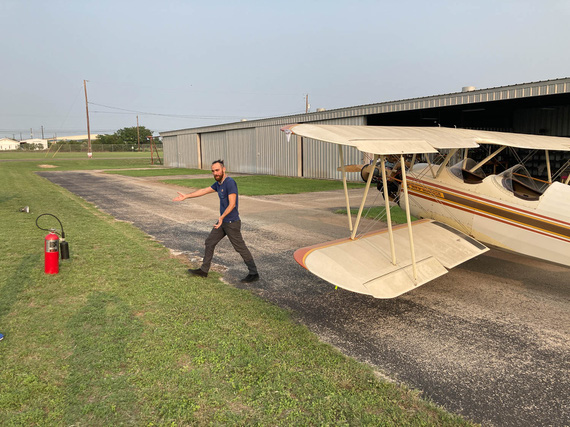
Final prep
... damn, that old Concord battery removed from the Cheetah years ago is weak and barely pulling thru.
... second try: no primer, so I have to pump the throttle a bit.
... she's alive!!!!!
I let the temps go up just a bit, and called N. He confirmed everything seemed to have been fine. We shut down, and went over every fluid fitting. All good.
Started her back up - I wanted to warm the oil to a reasonable temp and let her circulate for a bit, maybe 30 minutes - to get the juice flowing again.
On the second run, I revved her harder, and smelled something. Smelled like... burnt wiring? N. went around the engine, all wires, and everything he could see or think was close to being to a hot surface, or an electrical doodad. No signs of trouble.
We decided to proceed.
She ran just fine. I think we ran for about a total of 30 minutes. Shut her down, dragged her in. Went over the wires again - all of them. Nothing, all clean. There were no bad indications on any of the electrical instrumentation, either. So at that time, we left that as a mystery to be solved.
... and with that, we went home. We were tired.
Flying is better than walking. Walking is better than running. Running is better than crawling. All of these however, are better than extraction by a Med-Evac helicopter, even if this is technically a form of flying.
Up ↑
Carb Controls
...finished!
| On: | Feb 21, 2020 |
| In: | [Chickenhouse Charger] Electrical Rebuild |
| Time logged: | 15.95 |
| Tags: | 6781G, MA5 Charger, carb, throttle, mixture, cables, controls, engine, fwf |
Quite a while back I have measured the control cables and ordered them.
They took a long time to show up, and then I was working on this amongst other things. Just finished now :).
So, right to it, shall we?
First things first was to get thru the firewall. I had these fancy penetration trims for cables called 'CableSafe' from Spruce
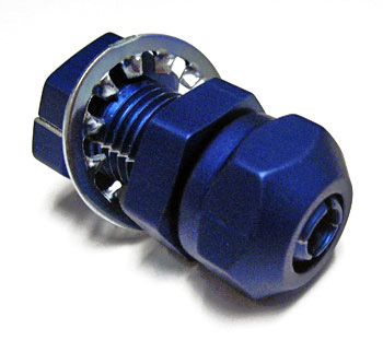
Cable Safe
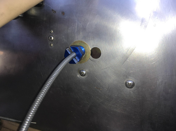
Throttle cable with it
Hmm... problem one. Washers clearly won't fit given the old holes in the firewall (Remo had grommets there, but I wanted something a bit more substantial).
No worries - we'll make me a special washer!
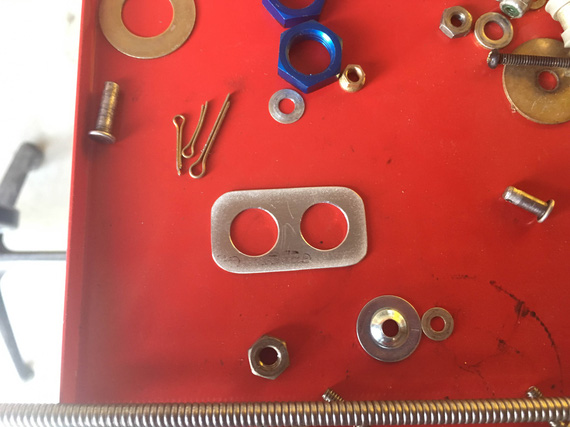
Special washer
Here's how this looks from the "airplane" side (ie, opposite the motor side of the firewall).
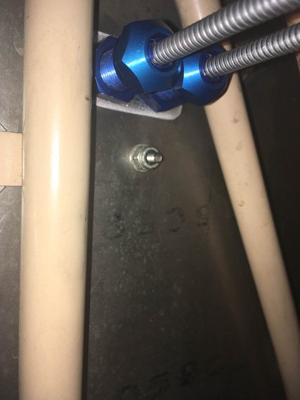
Cabin side of the firewall
And then, came fiddling. Most of it was done before ordering the cables, but I still wanted to check and re-check everything.
Hooked the clevis ends to the control cables, and the cables to the carb to verify everything.
When measuring, I figured I'd need a rod end for the mixture arm due to misalignment of the cable rod and the control arm. And the damn bushing, too - because the hole in the carb is 1/4", and the bolt is #10. I got some bushing stock from McMaster, but it was too long - had to shorten it with some creative sanding.
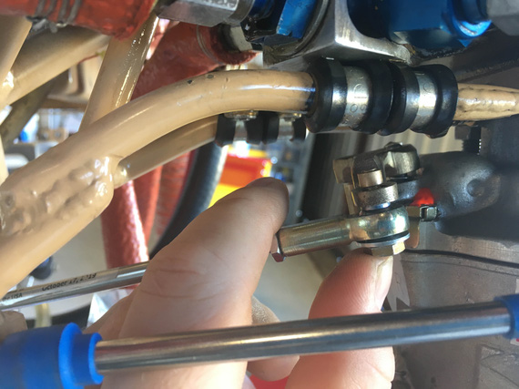
Mixture rod end hardware stack
Fun hardware stack, isn't it?
Bolt -> Large Washer -> Rod End -> Shim -> Bushing (inside control arm) -> Washer -> Shear Nut + Pin
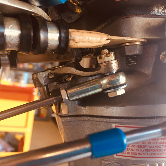
Bolted together
Throttle's clevis looks way more dull.
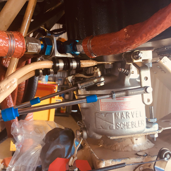
Throttle arm
Then, the airbox went on and I noticed something.
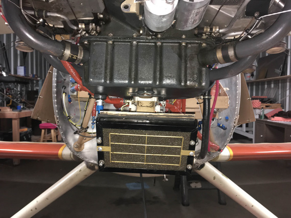
Airbox - do you see it?
See how it's tilted to the right (clockwise)?
I spent quite a bit of time there trying to figure out what's wrong. I put the cowling back on!!
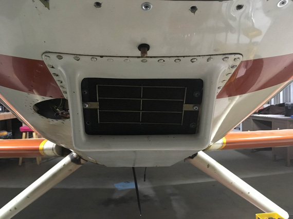
With cowling
Still crooked.
I kept thinking and thinking. It's motor -> oil sump -> carb -> airbox -> filter. That's how everything's bolted together. The first three are not "home buit", so I didn't think they were off. So it must've been the airbox and / or the filter mount.
Upon closer examination, I realized that the airbox was welded together way off, and is crooked itself. And the filter is mounted even more crooked in the same clockwise direction.
To confirm, searched all the pics I could find online of the plane prior to my having it (and disassembling the front).
It was hard to tell, but.. I think it was like this from the very beginning.
Phew.
--
Meanwhile, we had a night of a kind of weather when it rains without actually raining - you know, as if you are in a cloud with large droplets. Everything in the hangar got soaked, obviously. Including my clevis ends.
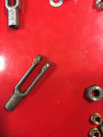
Rust on a new rod end?!
Aren't they supposed to be cad plated? Oh; and that was the first time I really noticed how cad plating sacrifices itself to prevent rust on steel - a lot of my hardware was covered in little white stains, which were cadmium having corroded and saved steel.
At any rate, I double checked the order paperwork. "Cad plated". Hmmmm. They definitely were not.
Called Spruce. She checked and doublechecked - and confirmed that indeed, their vendor stopped doing cad plated clevis forks specifically in that dimension - #10 end, #10 rod. They refunded my money, and let me keep the forks.
Called SkyGeek, asking about the clevis forks they sell. The lady goes, "yep, plated". I ask her to triple-confirm.
She takes about 10 minutes, and gets back to me - nope, not plated. She's sorry. No longer made.
John F., a local IA, confirmed. Only plain steel now, seems that cad plated forks are unobtanium. Crap! Oh well, I guess, paying attention and making sure to put oil or something similar on them from time to time is in my future.
--
Glenn had a carb temp probe in the Rotec TBI I am replacing, and I decided to try to keep it. Wire was cut way too short for how everything's on the carb (vs. the TBI), so I spent a bit of time pondering if:
- The probe was a thermistor, or a thermocouple
- If latter, could I successfully extend it
Pouring thru (mostly AeroLectric Bob Nuckoll's) notes on thermocouples, realized that some are magnetic. Let's see.. score! Magnetic indeed.
Got some multi-strand thermocouple wire of the same kind (red/yellow - I forget which metals those are :) ), and did some "back-bench" testing.
- Hook up the probe direct to the gauge
- Pour solvent onto the probe tip, watch for rate of temp change and lowest point
- Extend the wire now, do the pour again
- Subjectively decide if the indications were "roughly matching"
They seemed to have been indeed matching, so I decided to attempt to keep the probe.
But, problem. It'd interfere with the airbox'es mounting bracket (and for some reason, I didn't take a picture of that :( ).
So first, let's cut a slot that will let that bracket clear the wire.
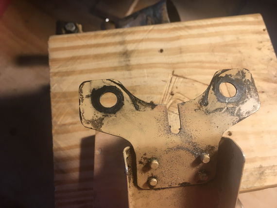
Slot
A bit of drilling, a bit of hacksawing, and a bit of filing.
Then,
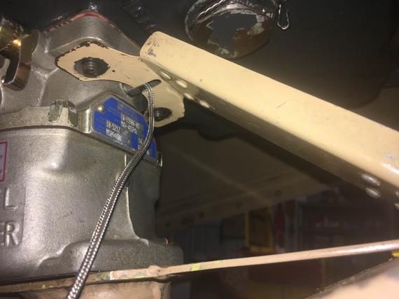
Trial fit
Nope, still not good. The carb temp probe there is the little thing that looks like a bolt with a wire sticking out of it - and it's hex was interfering a bit. But we cleared the wire now.
So, a touch more cutting was in order.
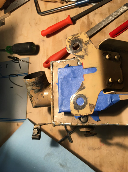
A touch more cutting
... and it fit.
---
Since I was messing with the airbox, needed to finish one last thing on it.
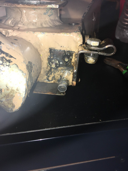
Carb heat bowden bracket
That bracket holds the carb heat bowden cable. Notice something weird? Yep, castellated shear nuts and pins. And, no, they weren't tight either, so the whole bracket business was wobbling around.
I spent quite some time pondering why would it be set up like that. Castellated, pin, not tight, wobble - all of that adds up to "he wanted that bracket to move around". It adds up really well too! The setup makes total sense if he wanted to have this arm move around - but there is absolutely no reason for it to do that! In fact, it's not good at all - steel bracket with steel bolts moving around holes drilled thru aluminum airbox - that would elongate and tear up those holes!
I decided that no. It should not move around, in fact. So,
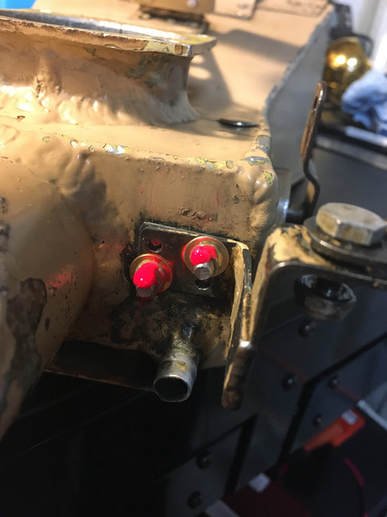
Hardware replaced
--
And then, the final hookups of everything after a long break. Routed the cables, and hooked them up with adel clamps where necessary (doing that conforms them to their final shape, which causes some changes in positions of the cable and controls and the range of motion).
Then, fine-tuned positioning of the controls, and tightened the pivot bolt on the bellcranks. Clevis pins might still need to come out - and that's why cotter pins aren't bent yet - just in case I'll need to unhook them again.
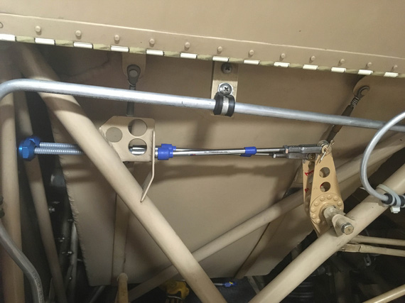
Bellcranks all done
Then, the penetrations.
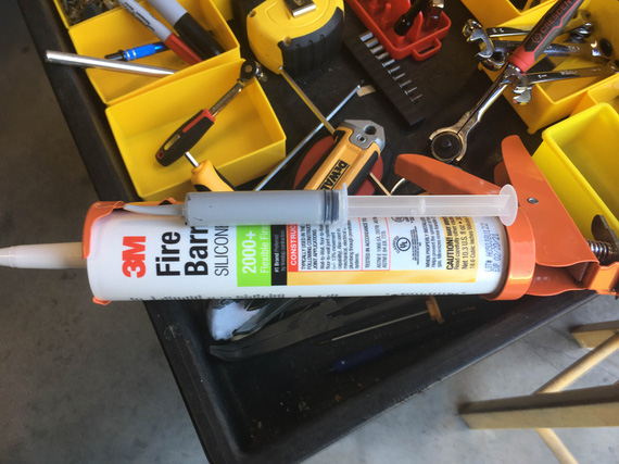
Fancy caulk!
Who said caulk guns have no place in aviation?
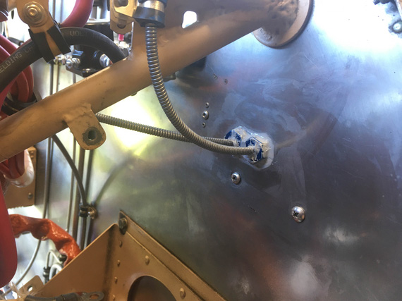
Sealed the big gaps
I wanted to stuff all the gaps with as much of this stuff as I could. I'll probably come back later with much more of the FireBarrier to put a good layer of it around this and other firewall penetrations.
And then, and then... Oh yeah! I could torque the throttle arm nut, and pin that in place!
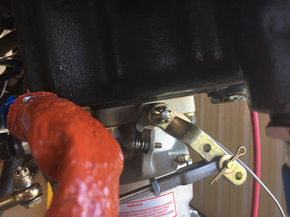
Throttle arm nut pinned
And finally, add more light machine oil to the carb bowl, so that all the rubber stuff won't dry out - all that moving of throttle back and forth pumped most of it out by now via the accelerator pump, I bet.
"Approach, what's our sequence?"
"Calling for the sequence I missed your callsign, but if I find out what it is, you're last."
-ORD ATC
Up ↑
Carb Control Cables
...just measuring
| On: | Sep 01, 2019 |
| In: | [Chickenhouse Charger] Electrical Rebuild |
| Time logged: | 9.3 |
| Tags: | 6781G, MA5 Charger, carb, throttle, mixture, cables, controls, engine, fwf |
Even before Oshkosh, I have decided to replace the Rotec TBI the Charger had when I got it with a good old MA4-SPA carb. In short, I do not trust the damn thing - especially with it being the sole component providing two out of three vertices of the proverbial fire triangle to the motor. That reminds me, I need to summarize my thoughts on Rotec...
Regardless, one of the things I got at Oshkosh was a rebuilt MA4-SPA from Spruce, and it was sitting in the hangar waiting it's turn. I knew I would need to order new control cables for it, so I decided to get that going, after all the alternator business was finished, because getting those cables will take me a bit.
Here's a fun aside. I knew this motor had a MA4 carb and Glenn "upgraded" it to the Rotec TBI. What I didn't know was precisely what kind of MA4-SPA it had (and there are quite a few models of that carb).
No problem. At Oshkosh, I went to nice folks from Tempest (which now owns MA Carbs) and had a very nice conversation with them. I asked if I should buy the carb from them, and they recommended Spruce instead, because it would be cheaper that way. And, they mentioned the $600 core charge (I'll spell this out - you must provide a good "core" (old carburetor) or get charged extra six hundred bucks). Ouch.
Ha! thought I. I am at Oshkosh! What could be easier than getting an old carburetor, especially since it's one of the most widespread models? No problem at all!
Laughing, I ran that by guys from Tempest. They laughed with me, and actually were very very very helpful, telling me what to look for when picking up an old carb.
No cracks in the body. Control arms should be present. Threads nice and not torn up. Venturi present. Etc etc etc.
Well, to the FlyMart we went, and sure enough, on a bench there laid a number of MA4-SPAs present, ranging from $250 to $450. Of course, I picked up the $250 one (it was yellowtagged by the way! In 1995, if I recall), dragged it over to Spruce, ordered a new carb, and handed them the old one I just picked up. So, $350 saved in about half a mile of walking. Not bad!
Here it is, in all it's glory, hooked up to my motor. You guys should admire my "economizer design" gasket. Hmm... I need to patent that and start selling them for $100/pop. Your fuel costs will go to 0! Now, you might not be going too far... but.. Fuel costs! Zero! With all the benefits, not going anywhere is such an insig.... Ahem.

Economizer Gasket

Carb
Well, okay. The carb was on, and cables came next.
The Rotec had it's control cables for mixture and throttle done completely differently than the carb. Glenn reused Throttle cable for Mixture on the TBI - it worked out well. He added a new cable, routed completely differently, for the TBI's Throttle.
Since this motor was originally carbureted, all I had to do is reverse engineer a bit the way Remo did the hookups.
Hehe.
Well, Throttle on the carb side wasn't that bad.
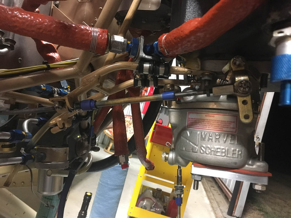
With a Rod End Bearing
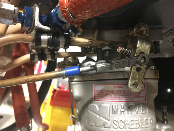
With a Clevis
It actually worked out a bit better with a Clevis, having the cable end centered nicely on the throttle arm. So I decided to do the clevis.
Next was confirming the "throw" - making sure that the throttle control range of motion, whatever it is, is sufficient (in fact, it must have some extra "padding" in it) to move the throttle stop to stop. Boy, was I in for a treat.
This Charger has reversing throttle quadrants, meaning that when the throttle goes forward, the actual control is pulled backward. Since forward on the control must translate into forward on the carburetor, the Charger has bellcranks to reverse the motion once again. These bellcranks are also a nice spot to tune out the range of motion.
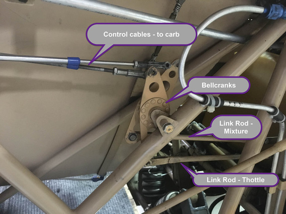
Control linkage
See, the relative distance of the top and bottom holes on the bellcrank to it's pivot point "convert" whatever range of motion is on the control (throttle quadrant) side to an appropriate range of motion on the carburetor side.
And Glenn changed them.
Not a surprise. The Rotec TBI had it's controls set up very differently as compared to a carb. Notice how in the picture the color of those bellcranks is somewhat off from the rest of the fuselage? That was my first clue...
My second clue was finding one of those bellcrank plates (minus the bearing) in the box of parts that I got with the airplane.
My third clue was me not being able to get the full range on the throttle.
Crap!
I am absolutely not set up to redo the bellcranks. Though they look simple, unless I want to make them from 3/16" steel, which would make them very, very, VERY heavy, I'd need a TIG welder. Or to MacGyver things with washers. And do quite a lot of trial and error.
I wanted to see if I could luck out.
Credit goes to Glenn here - he made his new bellcranks perfect for the TBI. The range of motion on them was just right... for the TBI. Because of that, they were asymmetrical - so I thought; maybe, just maybe, if I was to try them in different combinations, I would luck out...
And I did!
Now, these two paragraphs of text and one picture is me describing... about 3 or 4 hours of work - tweaking cables, turning bellcranks, checking, rinsing, and repeating. I think I did find a combination of orientation of these that gave me acceptable (but by no means perfect) ranges of motion. I think I lost about an inch on both of the controls, but that's not so bad, after all - you want extra room in your control's range of movement to make absolutely positive you can move the controlled thing stop to stop.
Okay, Mixture's next.
I hooked up the cable that Glenn used for throttle to the mixture control on the carb, to use as a "mock up", and kinda fished it thru.
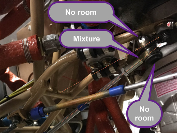
Mixture cable hookup
I had to use a rod end here. The cable wouldn't line up with the control arm on the carb for me to be able to use a Clevis there.... See how angled and offset that hookup is? I think Remo had a solid bowden cable style control there...
Another problem with the Mixture control is that the carb's arm has a 1/4" hole.. the rod ends need a #10 screw; which means that the hole on the carb arm is too large. No biggie though, I'll add a bushing to reduce it.
Yet another problem is that the bolt's head is way too close to the carb bowl, and I had to have it reversed like that (bolt "upside down").
There's not a lot of room on the top either. Planning to fix this problem with using of 1/2 size shear nut, and figuring out the exact bolt length (I ordered every bolt between -4 and -10 sizes).
And now, the routing of those cables.
The throttle cable routing was a given. I did not like too tight a radius in one of it's "turns".
I wanted to try to optimize the routing..... ha. Good luck there buddy! The battery box gets in the way (the battery is in a completely wrong place on this plane... it's reversed with the oil cooler. Oil cooler should be on the left. Battery on the right. This makes controls routing a breeze. But no.....).
I wanted to make sure to keep the mixture cable to not be too close to the beefy 4 AWG cable that will go from the battery to the master relay.
I had to reverse engineer previous routing of the cable, and figure out the best points to hook it up to the firewall.
I wanted to have my ANL fuse bases close to the master and starter relay. Ha! No way, with the control cables the way they would have to be.
All this was an exercise in misery, and lots and lots of time. I wanted too much.
In the end, the routing of the throttle will stay the same; the cable will just be shortened to make one of the turn radiusii bigger. The mixture will go nearby, and curl around the battery box.
I will not be able to use any other arrangement of solenoids and will have to stick to the old one. What's worse, I will not be able to use the new solenoid I got from B&C - it's mounting holes are very different, and, frankly, it's not worth it to drill more holes in already a sieve-like firewall - I'll stick with the classic "style".
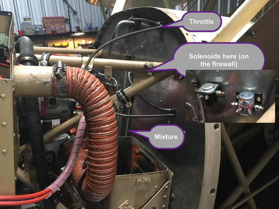
Approx. new routing
The mixture cable does look like it'll interfere with the solenoids, I know. In the final setup, it will be pulled away from the firewall and clamped to a couple of points I found.
...
More bad news? I long noticed a leak from the left brake bleeder valve; and decided to add a new valve to my next order from Spruce. I thought it was a basic valve problem. Well, went to look for it's dimensions, and found out the source of the damn leak, actually... Looks like someone tried to fix a leak there by making a bigger leak. The fun thing was, I didn't notice this before - the brake was too dirty...
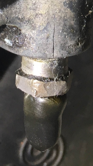
Boo!
Damn.. those cylinder housings are $300 each :(
But hey! I got good news too! I was checking to see if the ANL bases and the shunt will fit where the old voltage regulator was, and they fit perfectly, in just a perfect arrangement!
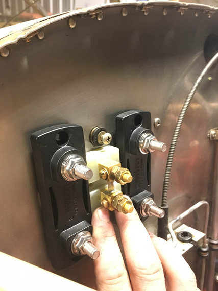
ANL bases and the ammeter shunt
I will reuse old voltage regulator rubber shock isolation mounts (I can't take them out; and they're sufficiently strong), and make a backplate to mount all this goodness to. Frankly, when I found this fit out, I liked it so much I bust out laughing.
And hey! My engine gauges showed up ;) Ain't they pretty?
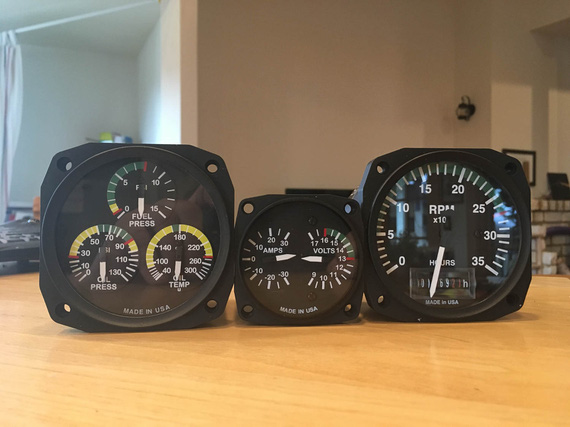
Engine gauges
I’m not speeding officer — I’m just flying low.
Up ↑
Race for the Engine
...or was it pickles?
| On: | May 17, 2019 |
| In: | [Chickenhouse Charger] 2019 Annual |
| Tags: | 6781G, MA5 Charger, Annual, engine, Rotec TBI, prop |
So after having discovered the electrical mess, I realized that she's gonna be sitting for a while.
Which meant...
Pickle time! Damn, this pickling thing is becoming a thing, excuse my tautologies...
I had to put her together enough to be able to run the engine to circulate and warm up pickling oil.
And she was apart. With intakes off, TBI almost off, no oil, and such.
Fuel / Intakes
So first, it was to be intakes.
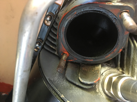
RTV where there should be none
Somebody put RTV to "seal" the intake gasket. Oh well.
Did you know that those 1 1/2 inch rubber hoses that go on intake tubes are much easier with very thin coat of oil?
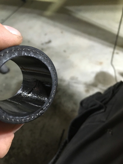
Oiling the hoses
And then, it was the TBI.
Recall that when I was putting her apart, I found pipe dope on the TBI inlet port?
Let me explain.
Fuel goes into gascolator. Then it branches: one branch goes to the engine driven pump, the other goes to the electric pump. Then, they go to the regulator on the TBI. Then, a couple of 90 degree fittings feed it into the TBI's inlet port, which has the "last chance" screen in it.
That's the port here, right above the airflow straightener:
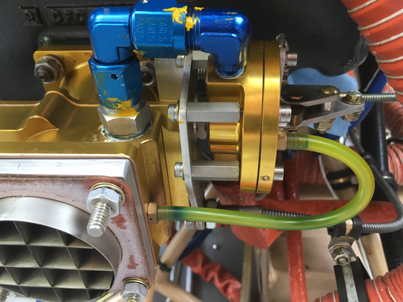
TBI from the down low
See that white gunk? That's Teflon dope. "Aircraft grade"; whatever.
Here's the problem.
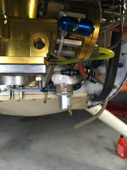
TBI inlet hole
Fuel has to go there, into that inlet hole. That's what the screen fitting screws into. Right past that, inside the TBI itself, there's a turn, another turn, and a spray bar that sprays gas into the intake, injection-style, thru a tube with a bunch of tiny holes. That's why there are screens in the fuel system: to prevent gunk from clogging up those tiny holes.
So now, what happens when you take a male fitting out of a female threaded hole, and the fitting was doped? Some of that stuff ends up on the female portion. Next time the fitting is put in, dope remnants will be pushed in past the engaged threads, and possibly clog up the works.
Not. Good. At. All.
That's why there is the copper crush gasket behind that screen fitting - to seal it to the TBI body w/o requiring anything extra. You can kinda see that gasket all smudged around with that dope on the first picture.
So I had to deal with it.. Clean it out somehow.
It was crumbly, but sticky enough to not want to come out.
I tried every solvent on hand. Nope.
I tried carefully scraping it out with a dental probe. Yeah, kinda worked, but I wasn't satisfied.
I tried every solvent in my buddy Dick's hangar. Nope.
In desperation, I drove to the local Home.. strike that, Aerospace, Depot, thinking about picking up every kind of solvent they had and I didn't.
And then, I remembered this:
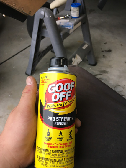
Goof-OFF!
I don't know what kind of concoction that is; but it worked! The hole was clean. Next time was a couple days after, and when I got back to the hangar, I discovered that it has turned into a lake :(
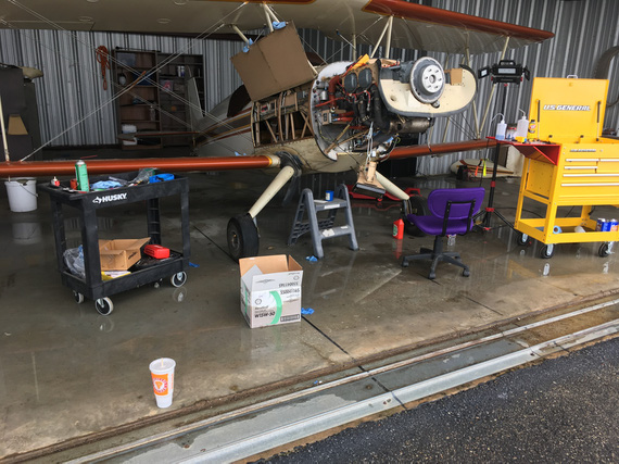
Lake in my hangar
Grading's all screwed up around our hangars, and when we get lots and lots of rain, they flood. Not too much though, luckily. This was the second time in the past few weeks - first time, I had my tools scattered around the floor. This time, I was smarter...
Anyway, back to the TBI. The rest of it went together quite nicely. I discovered that there was TorqueSeal put on the idle mixture screw.
Why? No idea. That screw is spring loaded. Should stay put.
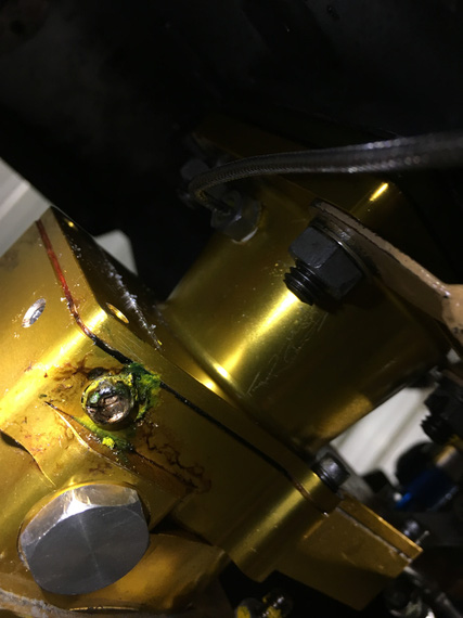
Torque Seal where there should be none
I wanted to flush the lines and then the TBI to make absolutely sure none of that dope went it. The best way to do that would be with the electrical pump; but I'm a one man show.... and the switch for it is 5 feet away from the firewall.
So, I had to rig me up a little doodad.
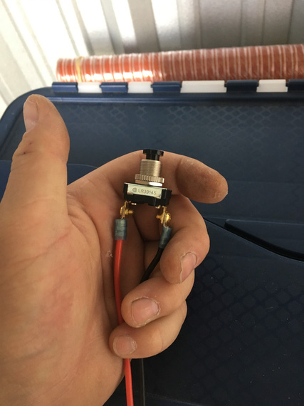
The simple click switch
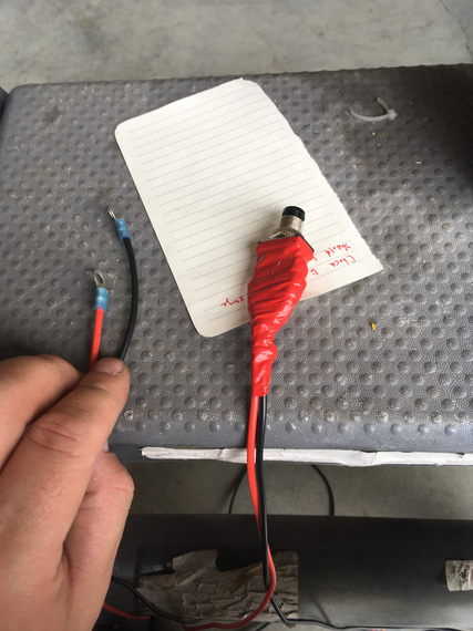
.. with ring terminals
The ring terminals were hooked up to the Master Solenoid in such a way that when the button was clicked on, the Solenoid would close.
The pump was turned on.
This way, I could click my button, Master Solenoid would close, and the pump would start running. Neat-o! I'll need it later, too.
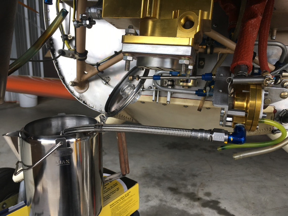
Flushing - braided hose provides nice bond to the airframe
The Pickling
I borescoped the engine (looked alright - I'll post a report about this later, maybe...); and it was time to fill'er up with oil.
Pickling oil was mixed up next, and into the engine it went.
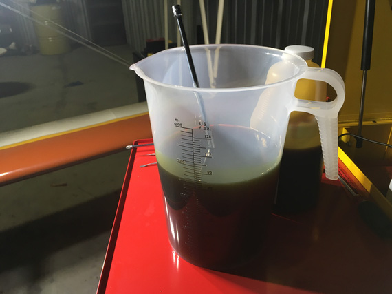
A pitcher of pickling oil
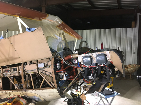
A recipe for a mess...
After filling the sump up, it was time to check for oil pressure. Lycoming tells you in SB1241C to pre-oil your engine by cranking with the starter in 10-30 second bursts until oil pressure comes up to 20 PSI.
Well, oil pressure gauge on the Charger is finicky, so I wanted it to at least move.
Oh wait. She has an ignition/start switch. No way I can use that to crank and not have a hot mag w/o messing with P-Leads.
Crap.
Also, I might want to crank from around the firewall (the prop was still off).
But I had my pushbutton doodad!
So I rigged it up to the starter solenoid this time.
Of course I misunderstood the way the starter solenoid was wired.
It had two terminals.
I thought one of them was ground; with the wire going to the firewall. The other then was supposed to be positive.
That didn't work.
I measured it - between those terminals - nothing. "Dead starter solenoid", I though. Crap! It was 8pm. Auto parts stores were closing soon.
I rushed to a nearby O'Reilly. Picked up a starter solenoid. Went back.
Measured it too. NOTHING? How come? Something was amiss.
Only then I started suspecting that something was off. That other terminal on the original starter solenoid I was hooking my positive wire to was all corroded and looked like it never had a nut.
OH! The way it's supposed to be wired is that positive goes to the same terminal where that wire I thought to have been ground was. It wasn't a ground wire - it was a diode. And the ground was off of the case of the solenoid.
Okay.
So, we're cranking now.
30 seconds. No pressure. 30 more. No pressure. Crap!
I unhooked the oil pressure sending hose (the one that hooks up to the line that goes to the gauge).
Crank. No oil. A couple bubbles is all I got.
CRAP!
The oil pump de-primed itself?
Kinda makes sense I guess? The plane was sitting for way too long :(
So, I took off the oil cooler return line. Dumped another quart of oil in there.
I had this hose fitting that goes on top of an oil bottle that was very neatly set up to mate with the engine oil hose's flare: so I could squeeze the bottle and push the oil in.
After the whole quart, I re-hooked the line back onto the oil cooler, and tried again.
Success! Now, I saw oil coming out of the oil pressure sending hose.
Hooked it up to the gauge line, and saw the gauge move, finally. Good.
Damn, with all that cranking I ran out my old battery I had put in there.
Now, have to flip the battery (to put in the good one - the flying one - I always use my old battery from the Cheetah when I mess with electrical, not to abuse the actual "production" battery).
Now, the top spark plugs go back in, the ignition wires get hooked up.
Prop time!
Bolt one - start it in. Bolt two. Bolt three.
Bolt 4. Doesn't go in? Not even a chance? What the hell?
I pulled the prop back off and laid it down. Put the front crush plate on top (that one positions the bolts).
No matter what I did, there'd be at least 3 out of 6 bolts that won't go in. This time, it was a few dry days, and I guess the prop moved enough to have the "top" and "bottom" holes (if looking at the prop horizontally) move closer together. It was off by almost a 1/16th.
So here I was. With an engine that was cranked for a total of a few minutes, and probably had scraped a lot of oil off of cam lobes and lifters.
With a prop.
I couldn't put on.
Which I needed.
To fire the damn thing up.
It was late. I tidied up, and went home.
The Prop
I wrote a note to Frank Johnson who made the prop that same night, and called him the next day.
He wasn't surprised. "Redrill" is a simple fix.
But I was a bit apprehensive, and this was a nice excuse to meet him. He's 2 hours away from me. We agreed to meet in a few days, at the first time he was available.
So, the engine with oil scraped off the lobes had to sit for another couple days.
Nothing I could do in that short a time...
Interlude
The weekend hit us; and it is a weekend in May, in Texas. Which means...
MUDBUGS!

The annual fit inspection
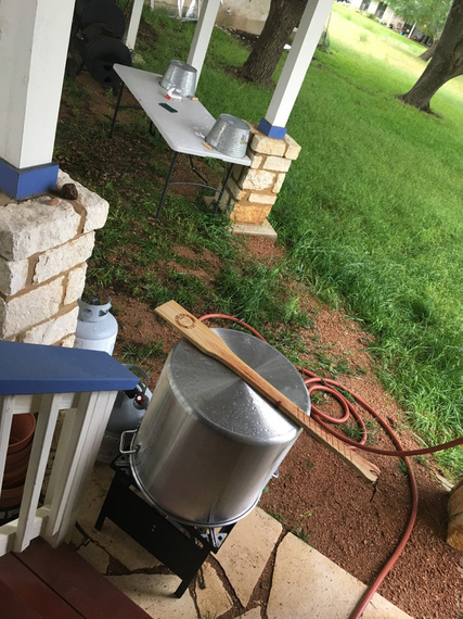
The setup

The fixings

Prep

Aliens!

The Boil
The Finale
Into the trailer the prop went, and to Frank's we drove.
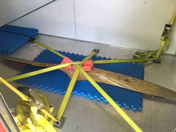
All tucked in
Of course, it took us 15 minutes out of 3 hours I spent there to fix it. The rest of it? Well, what can two guys who're crazy about airplanes do at one of those guys' shop and hangar? Hmm... What could we do? :)
The weather was swell, and I was in a good mood - and airport was on the way back from Frank's.
So, I went straight to the airport.
The prop went on beautifully.
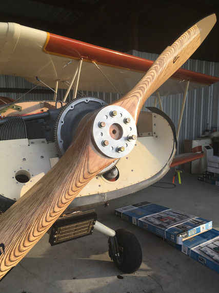
Finally, on
It was nice, sitting in a running, shivering airplane, to watch the sunset. If you looked up, it almost felt like flying. With the buzz, the shake, the smell and the noise.
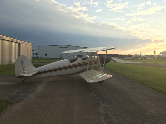
The Sunset
A couple days later, I went back to the hangar, sprayed the engine top and replaced spark plugs with desiccant.
Now, I can focus on the electrical mess...
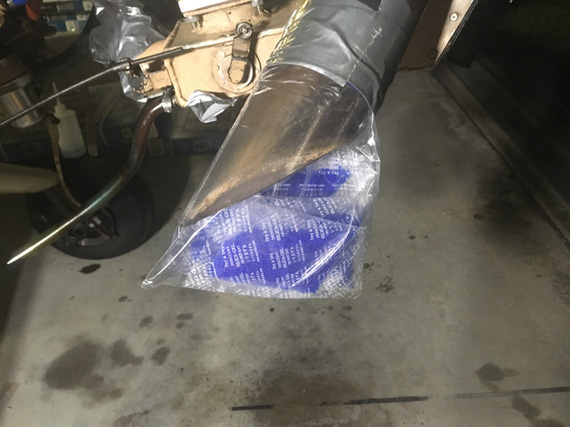
The Muffler plug
You can always depend on twin engine aircraft. When the first engine quits the second will surely fly you to the scene of an accident.
Up ↑
Metal Pickles
Russian autumn tradition
| On: | Oct 07, 2014 |
| In: | [Blog] |
| Tags: | engine |
No posts for 1 month and 5 days! Holy cow.
That's all been eaten up by a couple projects. One of them ended up being a complete redraw of all airfoil sections on the lower wings on the Skybolt; and nothing to write about (no pretty pictures, very routine work). Just lots and lots of cleanup.
Another one... was me following an old Russian tradition.
You see, during long winter months Russians' desire for fruit and vegetables (and mushrooms) is satisfied with pickled everything. Cucumbers, tomatoes, cabbage, grape leaves, dill (!), apples, garlic, fish (haha :) ), and other things which I don't know English words for.
My genes are calling. It's fall, and I had to pickle me something.
It was.. a disassembled Lycoming for the Skybolt!
Some weeks ago, a gentleman posted on the Forum about him selling an O-360-A4M, all overhauled, yellowtagged, and such, by Superior; with higher compression pistons from ECI, with everything needed to put it together minus the sump and accessories, for a very attractive price.
Best part was, it was disassembled, so I am to get all the fun putting it together without the disassembling and sending parts out for overhaul (and well, paying for that too :)).
In short, it was a great deal.
The problem? Well, I will not need it for quite a while. 10 years maybe, if I go with the speed I'm currently going at.
I figured, assembling and pickling it after would be a bad proposition. A much better one would be to pickle it part by part.
As usual, started with a thread on the Biplane Forum.
At the end of the day, I ended up using three things.
- Phillips Anti-Rust Oil
- STP
- Cortec CorrShield VpCI-368

Phillips 20W-50 Anti-Rust Pickling Oil

Good' Ol' STP
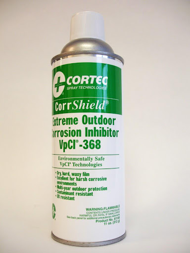
Cortec CorrShield VpCI-368
This latter substance is amazing. It's mineral spirits soluble, moisture displacing spray-on stuff that can protect up to 2 years in outside (!!!) storage. I'm storing the engine parts inside my house, so I figured it will do very good for a much bigger number of years.
It sprays on, and then dries over a couple days to consistency of candlewax. A bit sticky, but very tough. They claim it's scratch resistant.
Just in case I missed something or ended up scratching it off; I decided to also put a thick layer of Aeroshell grease on everything that's covered with CorrShield. Just in case.
And then...
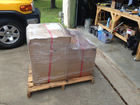
It showed up!
For smaller pieces, I first wanted to put them in sealed sandwich bags, with some STP / Oil 50-50 mix, and squeeze all the air out.
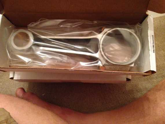
New connecting rod
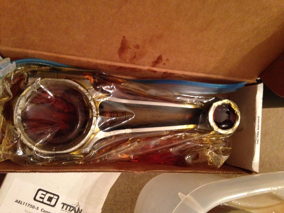
Now in the baggie with STP/Oil Mix
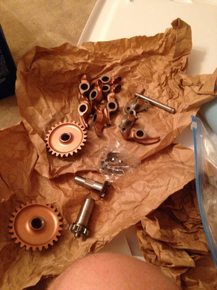
Gears and bits
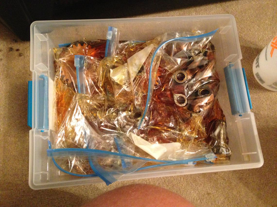
.. all bagged up
But after them sitting like that for a couple days, I didn't like how all the oil drained to the bottom of the baggies. So instead, I submerged everything in 2 oil/STP baths.
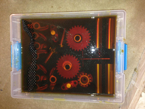
Piston pins, gears, rocker arms, misc accessory case things in oil/STP bath
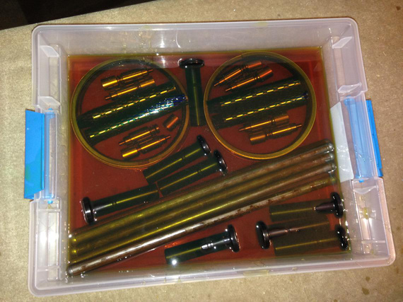
Pushrods, piston rings, tappets, etc in oil/STP bath
At this point, I ran out of oil and STP... And I had too much of CorrShield and grease -- and, after playing for some time with CorrShield and seeing how tough it is, I decided to use it on everything that didn't get into oil baths; even on smaller parts.
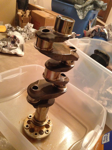
Crank
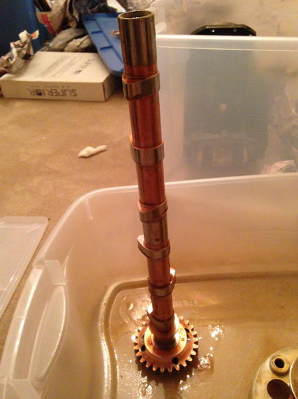
Cam
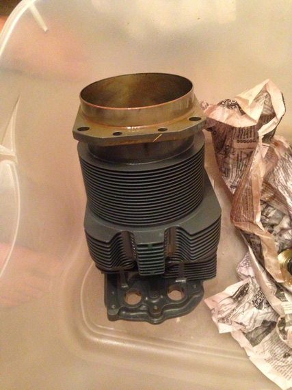
One of the jugs
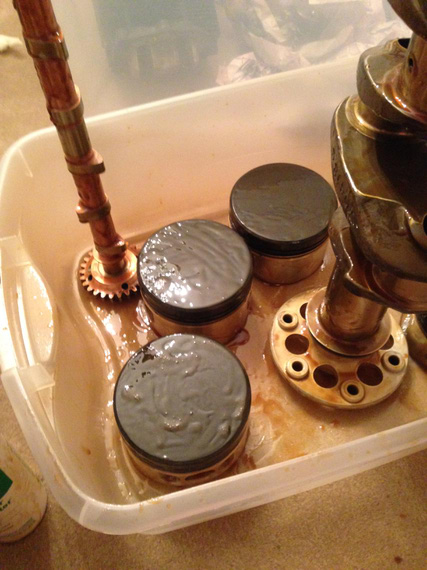
Pistons
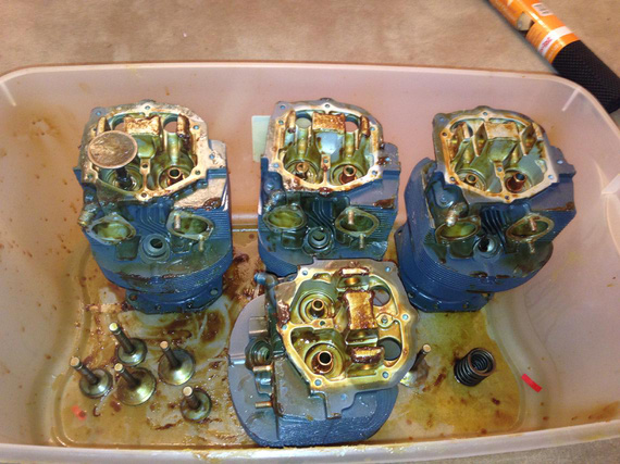
Jugs, right side up and tops CorrShielded and greased.
Some more small pieces stored "dry", covered in CorrShield and grease.
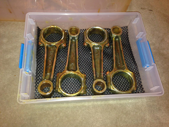
Connecting rods
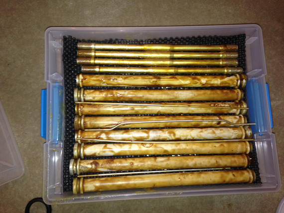
Thru studs and pushrod tubes
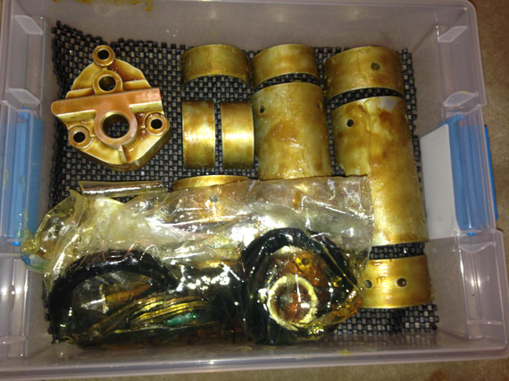
Bearings, oil pump housing and minor pieces
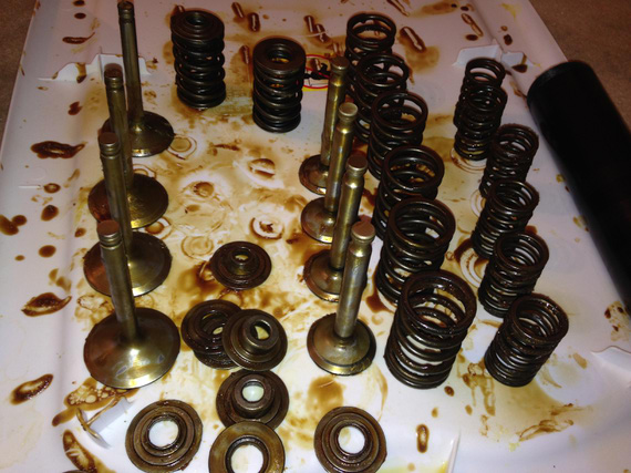
Valves.
This project took a couple weeks worth of evenings; and now my inner Russian is completely satisfied with his stash of pickles!
It's best to keep the pointed end going forward as much as possible.
© Copyright "79FT". All rights reserved. Feel free to cite, but link back to the pages cited.
This website only shows how I did things in my various projects. These pages are for information and personal entertainment only and not to be construed as the only way, or even the perceived correct way of doing things. You are responsible for your own safety and techniques.