[79FT]: Building Things |
 |
CGR30 and the Wheelpants
lots of upgrades
| On: | Dec 10, 2014 |
| In: | [Misc] Cheetah |
| Tags: | 9891U, cgr30 |
I'm done with my longest airplane project so far! No, it's not for the Skybolt, it's for my Cheetah. But it's an important one and was a great fun to tackle.
So, without further adieu...
The Cheetah never had an engine analyzer -- and I elected to get one, full blown, replacing all the standard engine gauges. I ended up picking the EI's CGR-30P because of it's roundness, compactness, and me generally liking EI a lot.
So, late August, it was Christmas. I got the box, that had a lot of boxes, with boxes, and boxes inside -- lots of stuff. Probes, aggregator box, wires...
First thing I did was put everything together on my dining table, just to make sure I understand the wire-up and that it works. I have even blown into the fuel transducer and was satisfied seeing it registering some "flow".
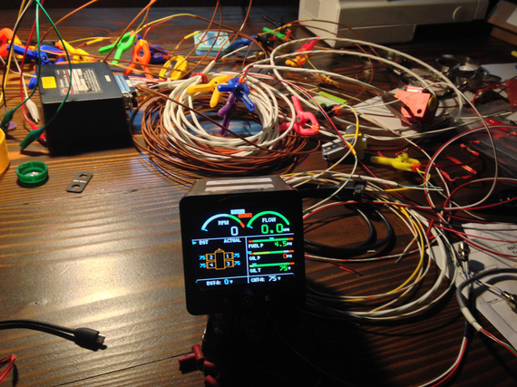
On the bench
And then, the install. The problem was, I also wanted to fly in between, so I had to plan the install in stages and make sure the airplane's flyable in between.
Session 1
First thing was running two out of three wire harnesses thru the firewall (all temp probes, and all pressure and flow transducers). I found a spot on the inside of the firewall for the box, and made sure I had enough length to run to the "aggregator" box.
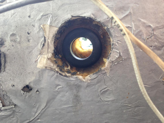
Reused existing hole, new grommet
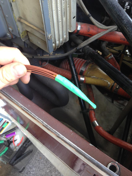
Wires bundled neatly for running thru
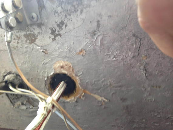
All wires are thru
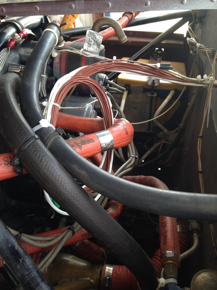
.. and neatly tucked away
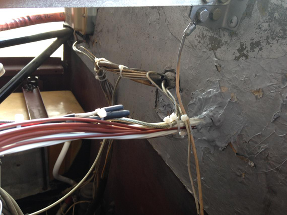
The hole with the wire harness sealed
Session 2
I was planning to fly out to friend's hangar and work on the probes install there. The luck did not cooperate -- very sluggish pull-thru on the engine start and heavy discharge right after on the ammeter hinted at the alternator failure.
Sure enough, it was. I ended up unbuttoning the cowl at the FBO I was hangaring at.
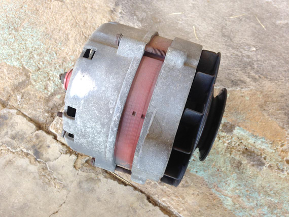
The perpetrator
That day, since the cowl was off and out of the way, I decided to continue and wire up as many probes as I could.
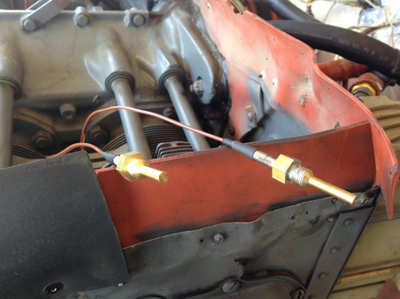
The CHT probes, lubed with anti-seize
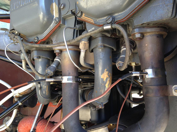
The EGT and CHT probes on one side
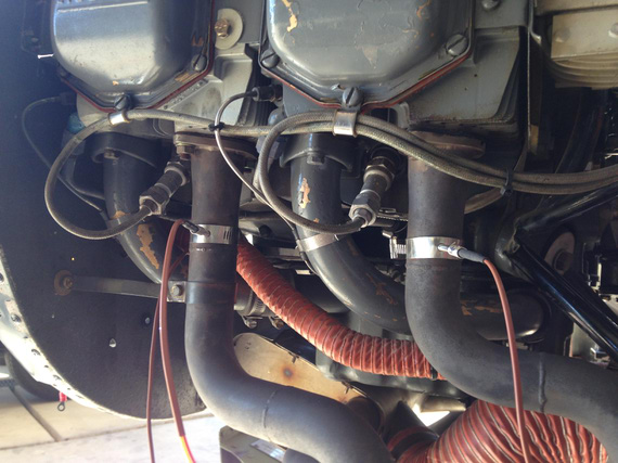
Probes on the other side
Then, came the time of connecting the probes to harnesses. As you saw on the pictures, probes have dinky little wires that aren't protected in any way. I asked EI if I should special-treat them in any way and they said no, but I still decided to get some fiberglass firesleeving from Grainger, and tucked them neatly away. Liked this much better!
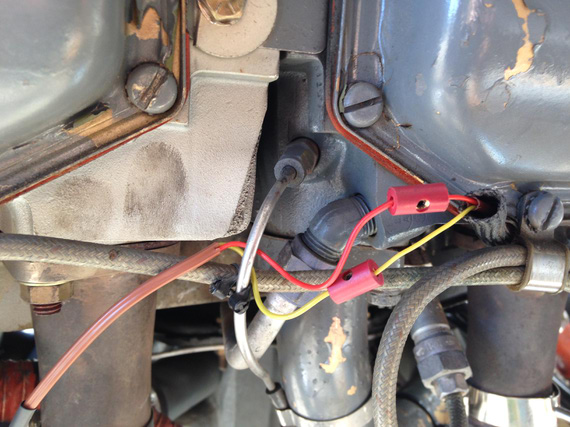
Connecting the probes. Notice the barrel connectors staggered, and fire sleeve
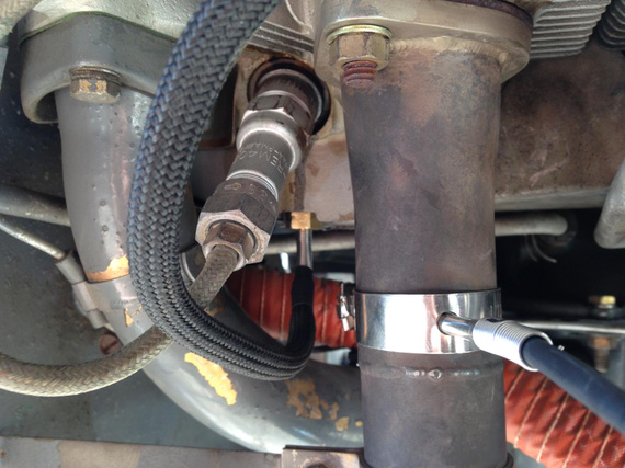
All sleeved
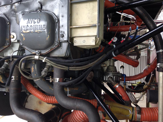
Sleeved and tucked away.
Sun was setting down at that time, and I called it a day.
Session 3
We replaced the alternator in the field, but I kept the cowl open to wire up the rest of the probes.
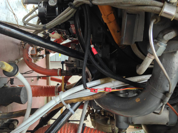
Installing and wiring more probes
I decided to install pressure transducers on the engine mount tubes using clamps, to keep them close to the engine outlets and hose lengths to the minimum. Consulted with EI again, and they said that's an okay idea.
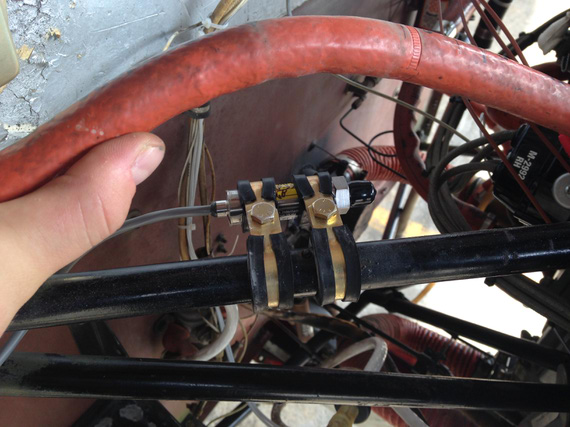
Oil pressure transducer
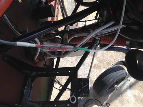
Oil pressure transducer wire-up
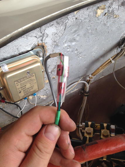
More wire-up
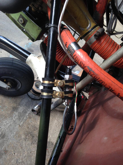
Fuel pressure transducer
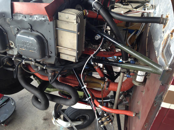
Fuel pressure transducer wire-up
That was it. I didn't install the fuel flow transducer yet.
Next, came closing that cowling, and a big break due to weather, travel, and life....
Session 4
This time it was a day to install the "aggregator box". All the probes feed into it, and there's a single wire that connects the box to the display of the engine monitor.
I didn't know what the exact length of the screws to mount it would be, so I decided to buy a bunch of different ones. Didn't have any way to measure the firewall thickness.
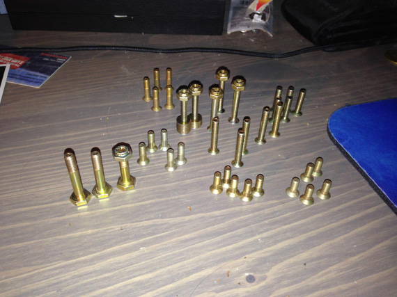
All that hardware
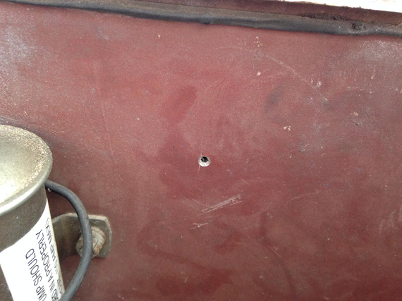
First hole in the firewall
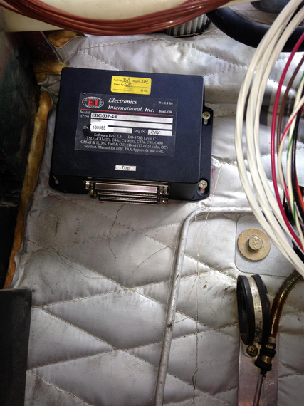
The "aggregator box" installed
That was a short day 'cause I had some things to take care of in the evening.
Session 5
So finally, it was time for a bunch of work behind the panel. Before then though, I decided to make a little panel insert that will hold the annunciator LEDs, the USB port, and the display dimmer.
As usual, played with the layout in Solid Works before I liked it. Decided on a 2 inch hole and fiddled with locations until I was happy. And then, used the final drawing as a template!
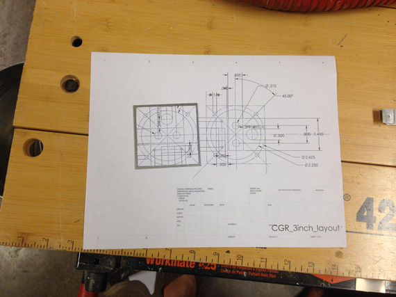
The layout
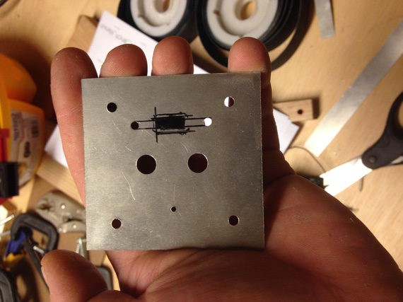
Cutting holes
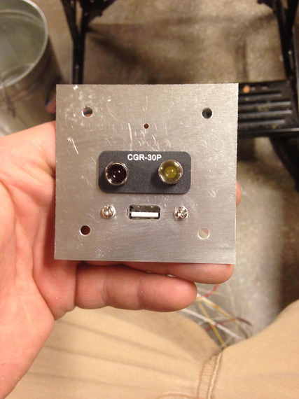
Test fit
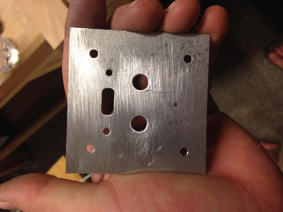
Cleaned up
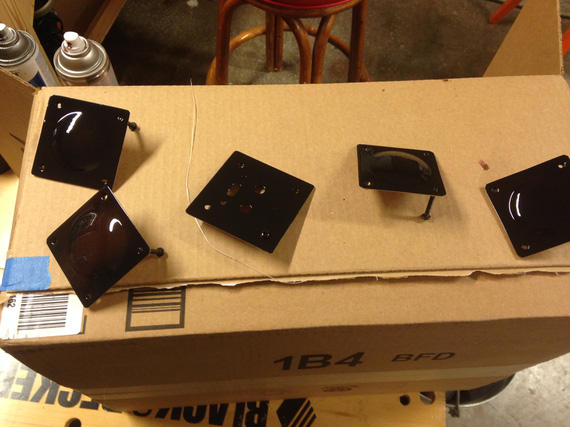
Painted. Also painted the panel covers
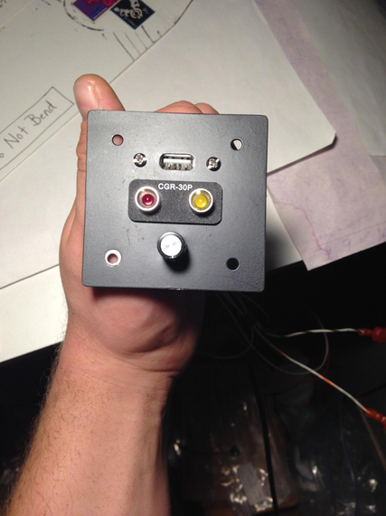
Done!
I also painted the panel covers that I took so long to figure out how to make.
Session 6
Finally, back to the hangar! This session took 2 days actually :). It was the time to install, wire up, re-position all the gauges on the panel, and such.
The old CHT, EGT and hobbs were to go. Clock was to be relocated to the position it's visible at (it was right under the panel eyebrow before). Davtron OAT/PALT/DALT/Volts gauge was to be relocated to another spot in the panel to free up space for CGR-30 auxiliary panel I made in the previous session. And, most of wireup had to be done. Harnesses connected to the box, ran to the display, and power.
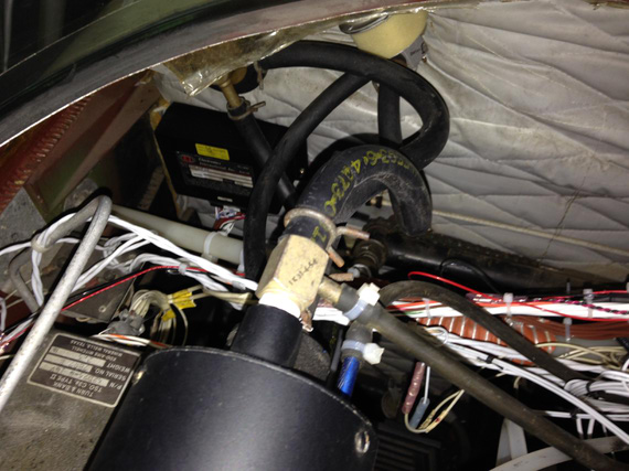
Box installed on the firewall, with harnesses coming in
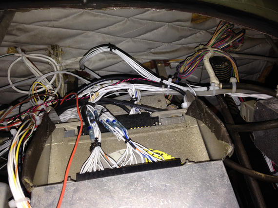
Behind the panel, sometime in the middle
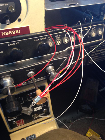
Ring terminals for power
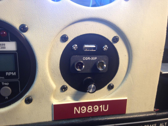
Auxiliary panel installed
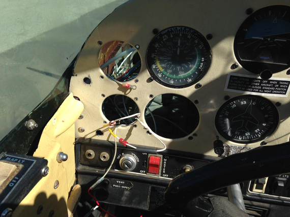
P-leads connected to mag inputs
And then, it was time for the first checkout.
I pull the plane out of the hangar, and hook the rest of things up with test leads.
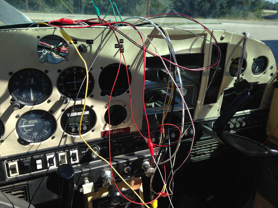
Test leads
Turn the enigne on, and observe!
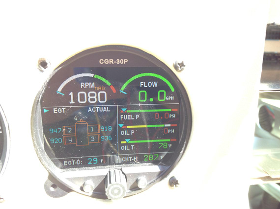
We're on! Oh, wait...
You see the problem? Yes, right mag is dead! Oh, and the old tach (I had one of those fancy Horizon P1000's that tells you if a mag is dead) is showing everything's okay. And, the engine starts doing this rattle sound, and quits. WTF?!
Thoughts about grounding something I shouldn't have grounded (ie, a plead) cross my mind. Then, thoughts about a loose screw somewhere next to the ignition switch crosses my mind.
I re-try. Same thing. Engine starts, runs a few seconds, and dies off. WHAAA??!
... I decide to go take a bathroom break. On the way back, another thought crosses my mind.... I get back, practically running, get into the plane - and sure enough! Fuel selector is "off". I switched it off the day before, before getting behind the panel. Just in case :) Phew.
The "right mag" problem doesn't go away though. I start diagnosing -- touching input wires to different pegs on the ignition key -- no matter which mag it is, "left" is okay and "right" is dead. Uneasy thoughts about a dead wire in the harness and having to undo the whole thing start crowding me... But, I decide to dig a bit deeper. Success!
Can you spot the problem?
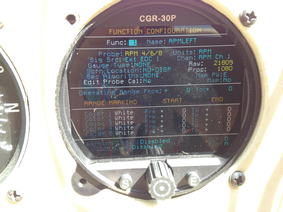
Left mag RPM raw signal value
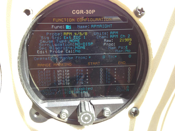
Right mag RPM raw signal value
Bingo! A call to EI, and a quick configuration update fixed that one.
Session 7
It was that time to go to Fletcher's and continue working on it there. Plus, my new wheelpants were ready!
Before I went though, I had to make one last missing bit. A bracket for the ammeter shunt. Did that at the home shop; and did it in a couple different widths to see which one fits better. That bracket was supposed to plug the hole left after old engine gauges removal, and hold the shunt.
By the way, I decided to wire the shunt into the battery leads. First of all, that's how Grummans are wired by default; and second, it actually shows you the actual discharge when you're on battery -- a good thing! It doesn't show the true load when charging the battery though -- just the charge current. That's okay though, as long as charge current remains positive I know my alt is okay.
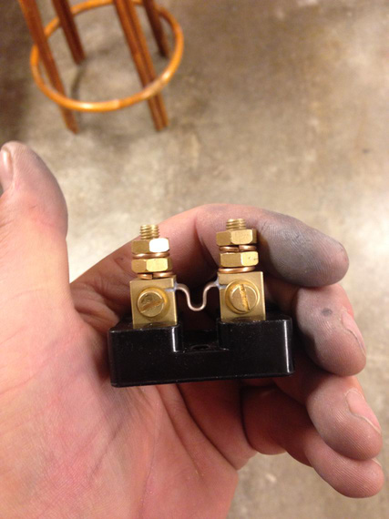
The shunt
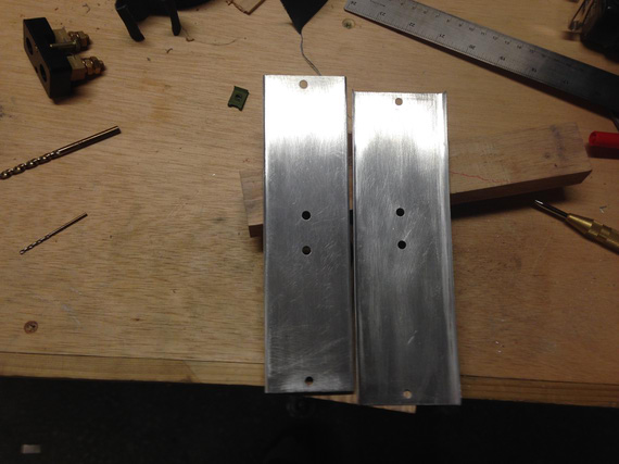
Two shunt plates
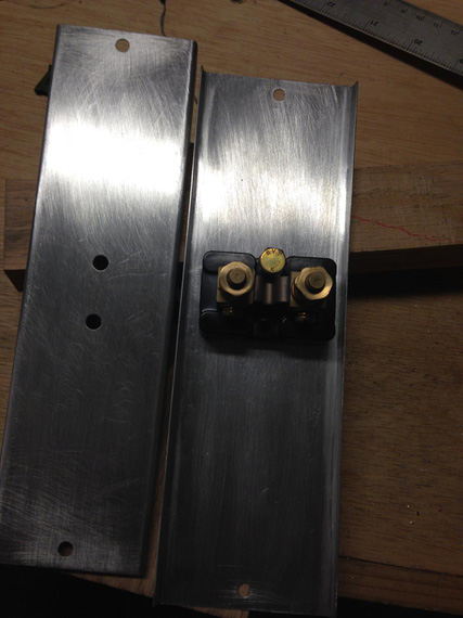
With the shunt
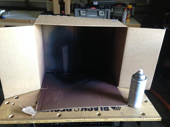
My makeshift paintbooth for painting these little boys
All that bending, sanding, filing, and drilling took about a couple hours in the shop.
Session 8
Onward - to Fletcher's!
We've measured lengths for all the new hoses; and decided to change all of them -- mine were manufactured 15 years ago. Also, found a small oil cooler leak, and decided to replace that bad boy. Oh, and I was finishing up behind the panel while David's guys were working on fitting and trimming my wheelpants.
I took out all the gauges, unwired everything that was to be removed, and installed the shunt... Then, it was time to call that a day since Clayton was supposed to fly me back, and I didn't want to make him go back after dark.
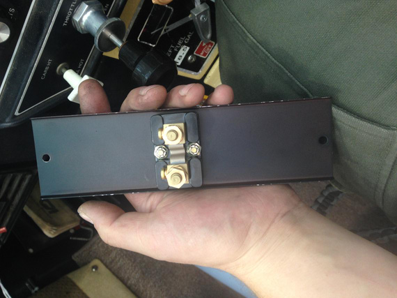
Shunt attached to the bracket
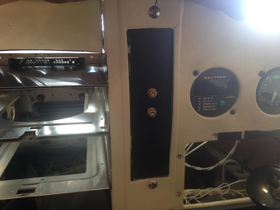
Installed. The bracket replaced old engine gauges.
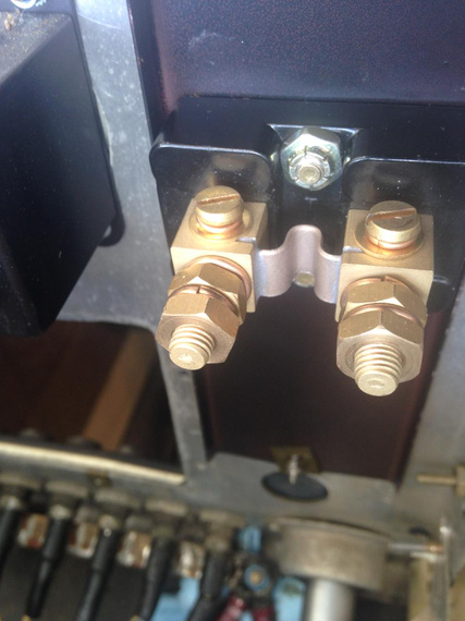
Shot from behind the panel
Session 9
I drove up to Fletcher's to finish up some more work behind the panel.
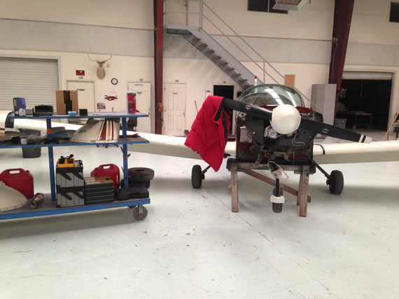
Another day
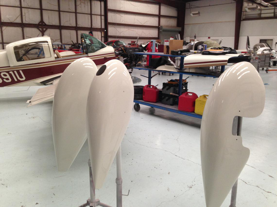
My new wheelpants, all painted!
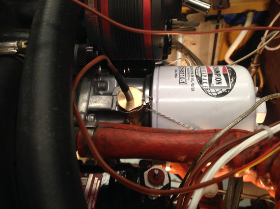
Oil temp probe installed and safetied
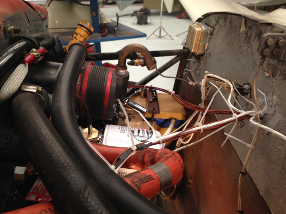
Final wireup
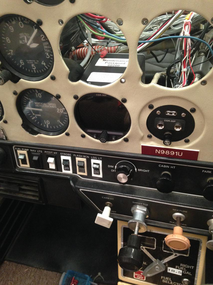
Display installed on it's final place
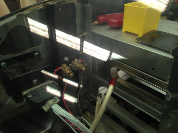
Starting to wire up the shunt
When trying to do the shunt, I realized that I didn't have the right size terminals, and the big enough crimper... Oh well, left that over to another day
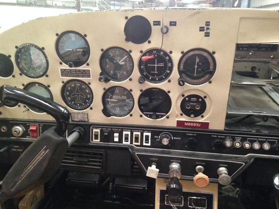
Final panel, with CGR and all the holes plugged
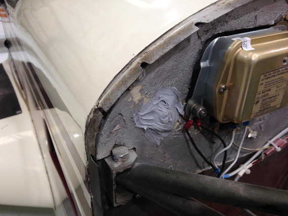
All holes left after oil and fuel lines removal patched
Also that day, I felt a blast and wanted to do more -- so decided to do the last finishing touch and clean up the oxidation off of my mixture knob. Acetone, baby!
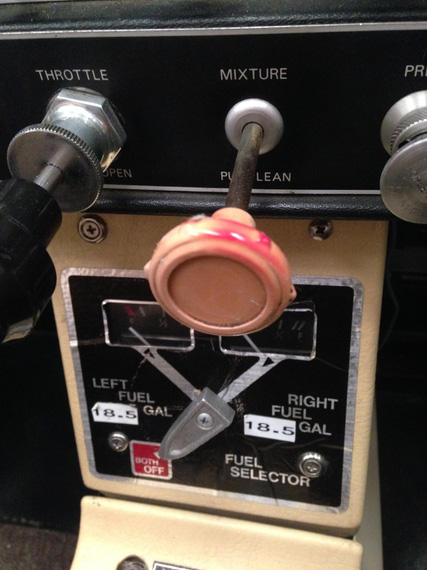
Before
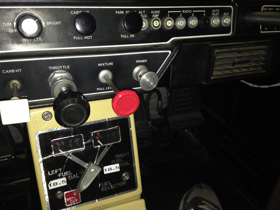
After
Good day!
Session 10
Last one! I arrived about a week later, to find the pants installed, oil cooler installed, and all hoses hooked up. John also hooked up the fuel flow transducer. And I made sure to have that crimper and right size ring terminals.
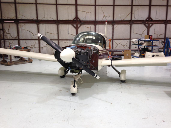
Wheelpants!!!
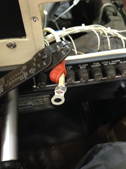
Battery wire ring terminal crimp
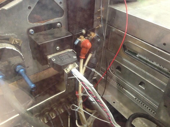
Shunt wired up
After that, we decided to temporarily hook up the cowling, and do the weight and balance, the right way. Too many changes. New oil cooler, new wheelpants, new gauge.. Plus, I know this particular airplane was never weighted at the factory, so why not.
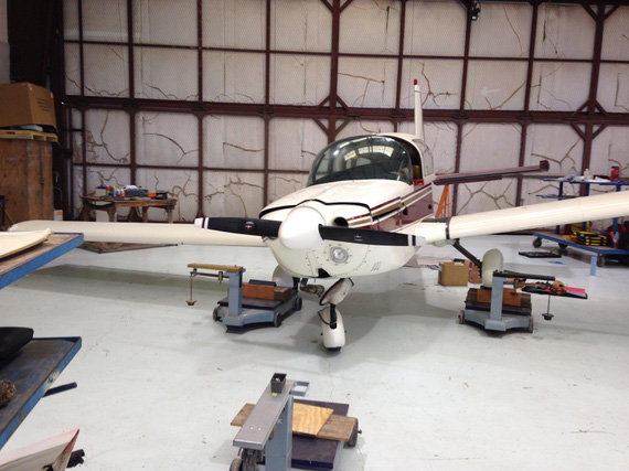
Speak of unusual attitudes! One wheel on the scales.
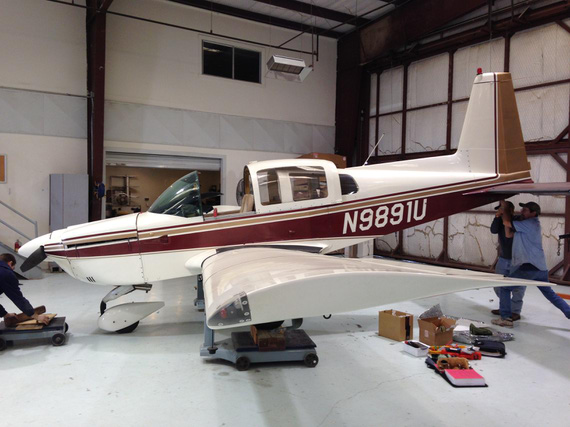
And another. "Pull up, Jimmy!"
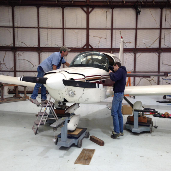
On scales. Leveling.
... and then, it was the moment of truth, sort of. Final checkup. Rolled her out of the shop, fired up, and...
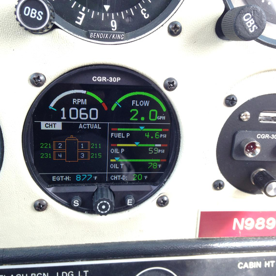
All green!
Shutdown.. checked all hoses -- a little drop of the oil on the oil cooler inlet. John said there was some oil in the hose, to wipe out, and try again.
Did just that. Fired up, and.. fuel pressure shows 0. "Oh shit!"... You guessed, right? Fuel switched off, again! Damn, that thing actually works!
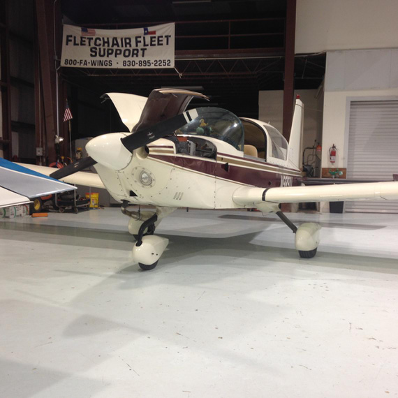
All done.
And so
I suppose I have to give some final thoughts.
Here's what I like about the gauge:
- Compact, takes only one hole.
- Not square! I hate square display engine analyzers. Don't fit right into the steam panels.
- Good documentation. Sometimes missing details like torques, but otherwise good.
- Great packaging and wiring harness pre-setup! Each wire came with a little sleeve identifying it. Didn't ever need to look at the harnesses diagram for wire-up.
- Great software and setup.
- Great support.
Here's what I didn't like:
- Single-stranded, unprotected wires for the probes
- The fact that I had to run the harness into the box, and then connect the box to the display. In my case, it made the wires longer, since they had to run from the in-hole in the middle of the firewall to the side where the box was mounted. Would've been easier to go straight to the display. I discussed this with EI actually; and they said that that was a long debated issue -- and they opted for the box, since that setup helps guys that have their engines far from panels (twins for example). I understand this rationale.
- #8 mounting holes on the "aggregator box" with countersunk screws. Would've been much easier if they had a #10 holes for AN3 bolts.
- Quality of OLP-1 barrel connectors. Very sharp plastic edges. I wasn't comfortable tying them to the wires just like that and had to hand-deburr all of them.
Overall, I love it. Great gauge, and I will be putting that on the Skybolt! :)
If it doesn't work, rename it. If that doesn't help, the new name isn't long enough.
Up ↑
Banging Sheet Metal
making bulges
| On: | Sep 03, 2014 |
| In: | [Misc] Cheetah |
| Tags: | sheet metal, cgr30, mechanicing, 9891U |
So on the Cheetah side, I am slowly ramping up for replacing all the engine gauges that I currently have on the panel with the CGR-30. I got it at Oshkosh, and finally, the box arrived a couple weeks ago.
Ain't she a beauty? Assembled on the bench for testing and familiarizing myself with it :)
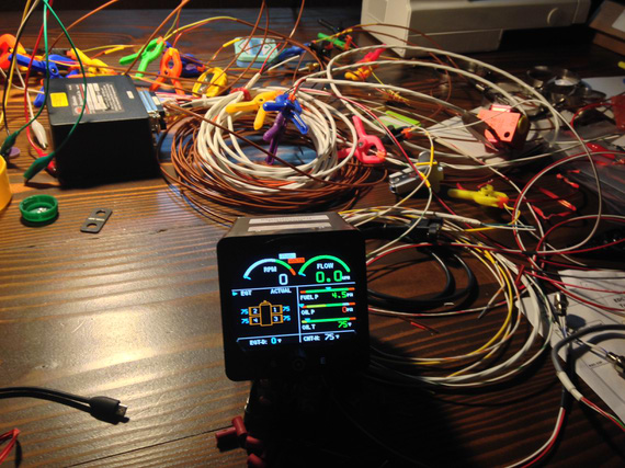
Ain't she a beauty?
Because of it, I will lose a few 2 1/4 inch round gauges, and I decided to make some covers for the panel, not to have unsightly holes in it.
Of course I could've bought them from Spruce or whatever, 5 bucks a pop, but if you know me, I would rather spend hours making something I can make. Besides, this is a nice first sheet metal exercise :). And, I wanted a nice domed bulge on each one of them. Just Flat wasn't enough.
So, I got to it.
First iteration was making a jig that would sandwich the sheet between two boards, with holes over and under the metal. Then, I would press a "piston" thru the holes using my vice as a press. Pictures are better than a thousand words.
Three piece jig + soon-to-be-'piston'. Oak boards sandwich the sheet between them. Ply plate has the "piston" and is used as a backing plate for it.
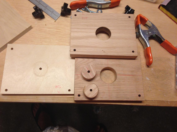
Jig pieces
That didn't work out. Vice jaws are not perfectly parallel, and the "piston" is not exactly the same diameter as the holes -- so it gets misaligned, even though there are four guiding bolts in the corners... Here's the jig assembled, and one of the first tries.
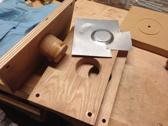
First try...
I think I tried it two or three times, with the same result.. no matter how much I tried to align the "piston", it would make a bit more pressure on one side of the jig than on the other, either resulting in a tear, or in an uneven "bulge".
Out of desperation, I took a piece of metal, laid it over one of the holes in the oak jig board, and started banging away - and was surprised! I was getting almost what I wanted, just not clean enough.
I tried sandwiching the metal between two plates and banging via the top hole - and made a fairly nice bulge! The edges weren't very clean, but I reasoned that if I opened the top hole up a bit more, that would give me access to the edge, and I will be able to bang on the edge a bit more, defining it better.
Ha! No. Same stuff.. I was able to make a fairly nice bulge, but the edge will be all "torn" and ugly.
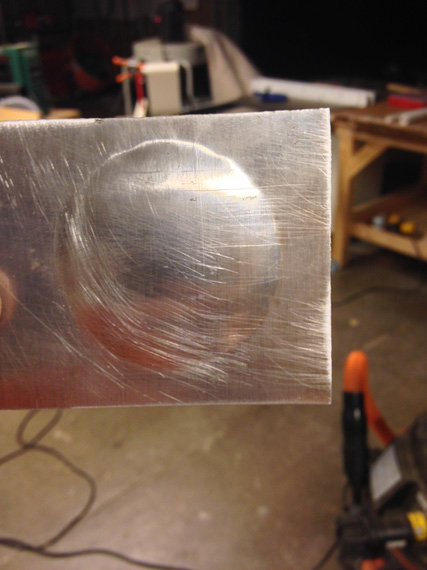
Bulge is there, but the edge is god awful
I also tried putting a profile on the bottom, "die" plate of the jig, with a very sharp edge and curvature under it.
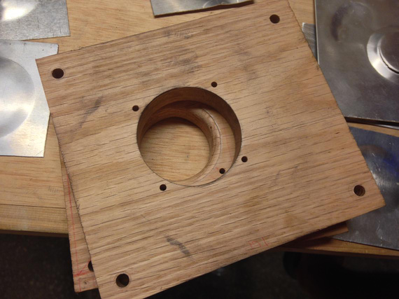
Second jig
No luck. I think I spent a couple hours, making over ten "bulges" and trying different hammering techniques...
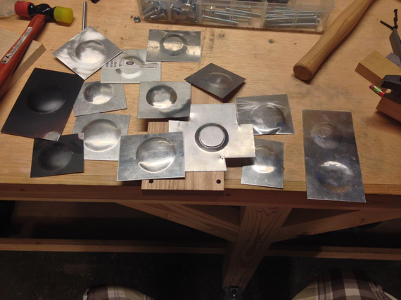
All those tries.
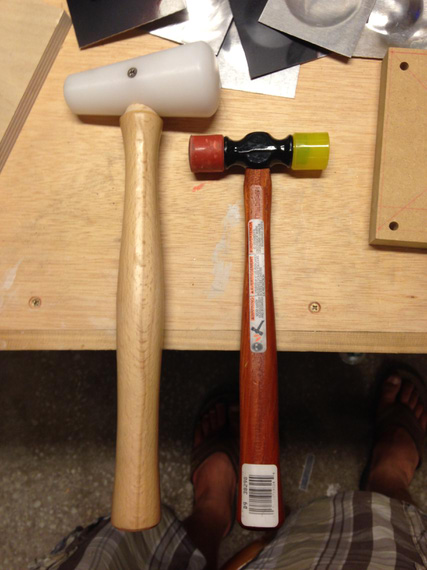
The Two Hammers
So I gave up, and emailed Bill Rose, the gentleman who gave me all the SolidWorks parts for standard HW, and, in general, helps me a bunch with my silly SWX and other questions, for advice.
Bill suggested using MDF for the jig instead of oak. Apparently, irregularities in wood grain would make it hard to define the edges uniformely. He also suggested using corking tools akin a big "chisel" on the edges to better define them.
..and.. it worked!
The third jig is ugly, but it works. Upper hole is enlarged just to get access to the edges (I didn't bother making the top hole concentric with the bottom or even round; there was no need).
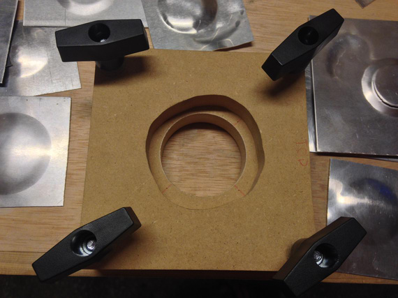
The third jig
I used the two-headed plastic/rubber hammer's rubber head as a corking tool, lightly hitting it with the plastic mallet, and having it slide from the edge into the center of the bulge.
This bulge still has some "orange peel" on it and needs to be smoothed out, but the edges are very well defined!
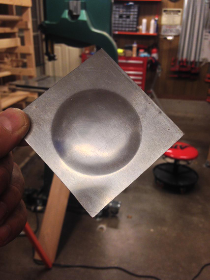
Check out those edges!
But of course, I screwed up again - the hole in the bottom, "die" plate of the jig, is of a wrong diameter (I used the wrong holesaw). But hey, at least I think I figured that technique out!
Good evening in the shop tonight :).
Why did God invent women when airplanes were so much fun?
© Copyright "79FT". All rights reserved. Feel free to cite, but link back to the pages cited.
This website only shows how I did things in my various projects. These pages are for information and personal entertainment only and not to be construed as the only way, or even the perceived correct way of doing things. You are responsible for your own safety and techniques.