[79FT]: Building Things |
 |
Wings and Control System
done..! Well, almost
| On: | Aug 12, 2014 |
| In: | [Skybolt] Wings |
| Tags: | CAD, lower wings, ailerons, control system, fittings, fuselage |
Ahh.. Finally. One week for a business trip, nothing done. One week and three days for Oshkosh. Nothing done (or rather, other stuff done :) ). And many more hours of fighting Solid Works; I finally have something to log! :)
Incidence and Fittings: Finishing Up
First, the incidence. Last time, I was trying to figure out how to deal with vertical fittings having to align with spars angled at 1.5 degrees up (incidence). A good discussion on the Forum ensued, and I figured (aside from me having to buy a +/- .0001 Precision Axe), to drill the hole at 1.5 degree angle in the front fitting, and forget about the little gap that shows up there, and weld the rear fitting in place. So something like this (you're looking at the fitting pair from the side, the CL is the hole centerline).
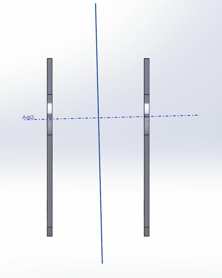
A pair of fittings, with the hole drilled at an angle
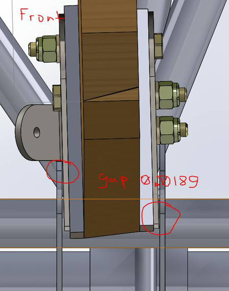
Gap that shows up when fittings are vertical, and hole is at an angle.
Note to self: When building / finish welding, I might reconsider and bend the tops of that fitting 1.5 degrees back to make everything flush. I probably will.
Back to the Control System
Next item on the list was bellcrank-to-aileron pushrod, which is tricky. See, if it's straight, it doesn't clear all the hardware.
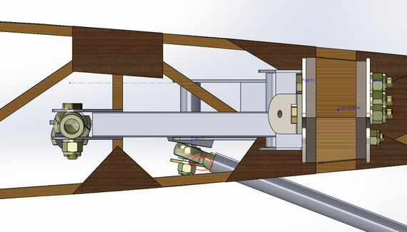
Pushrod is not clearing hardware if straight
So it had to be slightly bent to make the bellcrank side rod-end a bit more "horizontal", if you will, while not "horizontal" enough to hit the spar above.
This sounds easy; and probably is -- but tweaking splines, checking, re-checking and tweaking again while checking for full range of aileron's motion took up most of the time here.. I think I spent a good 10 hours or so just tweaking that one pushrod... And finally, here it is -- notice a slight bend in it. Just a touch less bend and it hits the washer under the bellcrank side rod end, just a touch more, and it gets dangerously close to the spar.
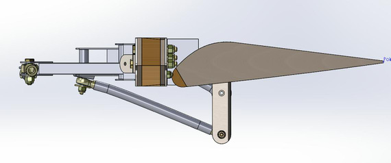
Aileron pushrod, tweaked to fit
Finally, I was able to move the aileron linkage on the wing model and check the idler - bellcrank pushrod for ribs' verticals clearance. It clears! There's another clearance issue though - by the looks of it, it won't clear the compression struts (3/4 x 3/4 inch struts go in the middle of the ribs, forming wing bays along with drag/anti-drag wires) by the looks of it. So struts and wires it is, next, amongst other things..

Control system looking from the wing butt: won't clear the compression struts
Fitting Wings To the Fuse
For some reason, Solid Works gods decided to start hating me here. Remember the note about angled hole in the front wing fittings pair? Assuming that pair is mated to the fuse (lower longeron); front spar butt hole (ha.. ha ha.. haha..) mated to that angled hole in the fittings' pair should produce correct incidence; and dihedral can be set with wing spar centerline mated to, say, one of the fuselage's crossmember's centerlines, at required 1 degree angle? Ha! Yes; that worked -- but for some reason, would cause all kinds of shenanigans the moment I would make the SWX assembly flexible (== allowing me to move control surfaces of the wing sub-assembly as a part of the overall assembly).
Yeah-right. -3 hours of my life until I gave up.
Instead, I made a virtual "jig" -- another sub-assembly containing planes at correct dihedral and incidence angles. Wing's "Top" plane would mate to the "wing" plane of the "jig"; latter ("wing" plane) would be at 1.5 degree incidence / 1 degree dihedral. That worked.
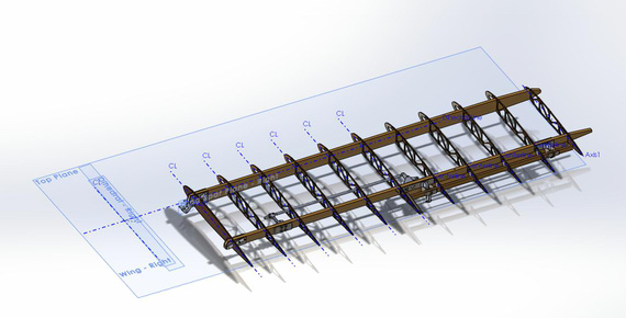
The virtual "jig" made of planes.

Dihedral of the lower right wing
That same "jig" assembly contains fittings mated to the wing spar -- and then, that "jig" subassembly is mated to the fuse via fittings - to - longerons mates.
That, for whatever reason, worked. After that, 10 more minutes of making one final pushrod connecting idler to Actuator Arm on the Torque Tube, and..
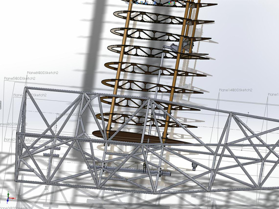
Control system all hooked up and working!
Happy me, making virtual airplane noises moving virtual torque tube moving virtual control system actuating virtual ailerons... Who says CAD isn't fun? :)
Now, back to those compression struts, only to find out that the pushrod does NOT clear... Le sigh.
The main thing is to take care of the main thing.
Up ↑
Lower Wing Fittings and Torque Tube
cleanup, and more bending
| On: | Jun 16, 2014 |
| In: | [Skybolt] Fuselage |
| Tags: | CAD, fuselage, torque tube, control system, ailerons, elevator, lower wings, fittings |
For starters, cleaned up the torque tube; added all the hardware (thanks cwilliamrose again for AN hardware models!) and proper mates. Was a nice warm-up, and came out real well.
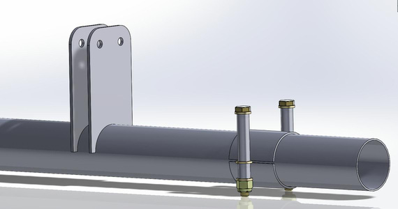
Torque Tube, Cleaned Up with HW
After that, added the lower wing front fittings to the fuse. Piece of cake! :)
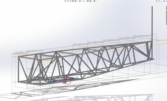
Lower wing front and gear rear fittings
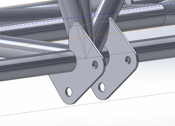
... and zoomed in.
Notice on the above picture how they interfere with the tubes of the fuse truss (geometry penetrates one another). There are a couple ways to fix that; plans just call for 'trimming in place'. Note to self: figure out if the weld should only be around the bottom longeron; or if to weld the top of the fitting to the vertical too?
The cool thing about SW is that I can "cut" in place; add a bit of margin on the real pattern for the fitting, and make it to fit without constant trial and error.
And then, lower wing rear fitting.. that one is tricky due to the way it's dimensioned on the plans (it makes sense plan-wise, since it maintains clearances between longerons and spar butts, etc; so hole positioning takes metal thickness into the account). Can't believe it took me 2 hours and a few tries to figure out how to model this right. Learning curves be damned :)
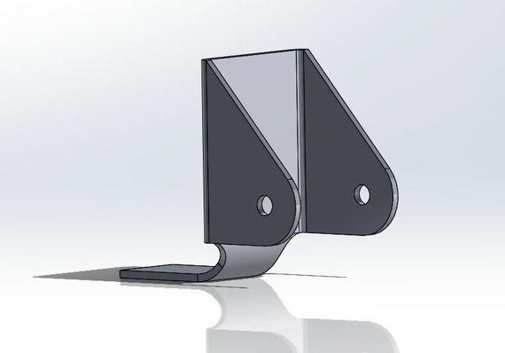
Lower wing rear fitting
Now, the reason for all that trouble is that getting the flat pattern out of that is just 1 mouse click!
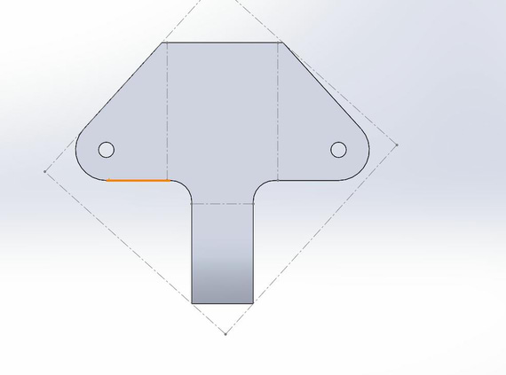
Lower wing rear fitting
I think this was a great day. :)
It only takes two things to fly, airspeed and money.
Up ↑
Torque Tube Basics
for now, just the bare minimum
| On: | Jun 15, 2014 |
| In: | [Skybolt] Fuselage |
| Tags: | CAD, fuselage, torque tube, control system, ailerons, elevator |
Started modeling just the very basics of the torque tube. The idea is to hang it on the fuse, attach the aileron pushrods to it, and check clearances in the wings (and finally get to start making them! :)).
Just a few screenshots today. Lots of time spent reading plans (haven't paid as much attention to Fuselage / Control Stick setup as I did to the wings).
Gladly, I had the truss model from way back when (I did it to learn SolidWorks Weldments feature).
Anyways, pretty pictures below.
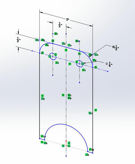
Aileron Actuator Arm Sketch
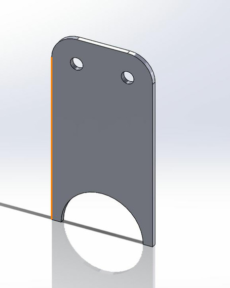
... and model.
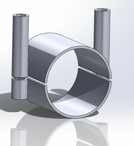
Torque Tube Collar
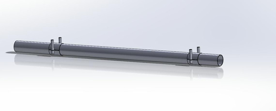
Very basic model of the Torque Tube (but all I need right now, minus the aileron arms)
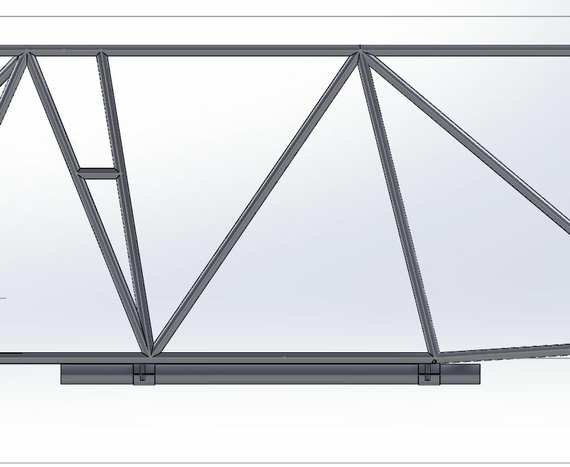
Torque Tube on the Fuselage
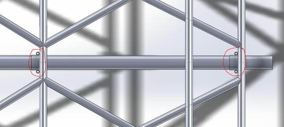
And eyeball alignment check - fits!!! :)
Remember, you’re always a student in an airplane.
Up ↑
Pushrods, bearings, and clearance
slowly getting there
| On: | Jun 09, 2014 |
| In: | [Skybolt] Wings |
| Tags: | CAD, lower wings, control system, ailerons |
In the past couple of evenings; have continued hanging virtual control system on the virtual wings.
Thanks to CWilliamRose from Biplane Forum, I now have quite a bit of models of AN / MILSPEC bearings.. REP3H5 included, but he didn't have REP4H6, so that had to be done first..
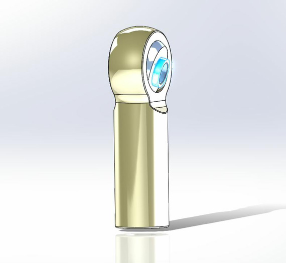
REP4H6 bearing model
Couldn't find a few dimensions; but my rationale is as long as the basic eye height / bore / shank are there, and the ball 'rotates', that's good enough for the purpose of my alignment checking, for now at least. Ill revisit if I start getting into tight corners.
Next, hung the Idler, bearings, cleaned up the model (funny, lower wing assembly is technically my first serious SolidWorks model, so I keep cleaning it up as I go, killing stupid things I did back when I didn't know any better).
Sigh... I will need to hang the wing onto the fuselage model to make sure the pushrod doesn't hit verticals -- clearance is there, but might not be enough.
Here's the wing model with the pushrod:
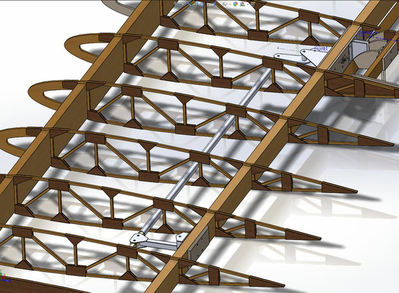
Idler, bellcrank, and pushrod -- there is clearance, but is it enough?
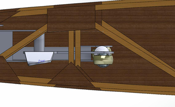
Here, it's looking at the rod from the tip, the rod is that white thingie right of the rib verticals
So, I guess, to the wing fittings and control stick assembled with fuse models tomorrow.
And to finish today off, here's the full zoomed out picture of the lower wing, as it is right now.
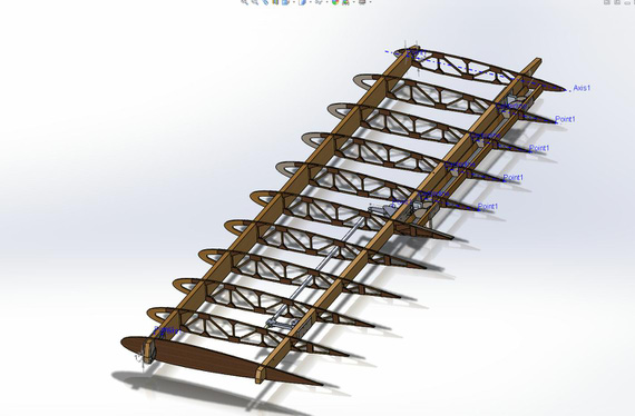
The wing
Unofficial grading standards for low level navigation:
You can't be lost if you don't care where you are.
Up ↑
Bellcrank and Idler
Bending and twisting virtual metal
| On: | May 22, 2014 |
| In: | [Skybolt] Wings |
| Tags: | CAD, lower wings, control system, ailerons |
It's almost 5 am and Im finally done with the bellcrank alignment! Phew.
By the way, sheet metal stuff in Solid Works is amazing! You give it the bend lines, radii, and a couple more parameters; and it automatically creates both the bent item; as well as the flat pattern. Print the pattern, glue, and start bending -- it will show you which line, how many degrees, and in which direction to bend. Ill post one of those final drawings later, when I get around to printing them and bending some actual metal :).
Anyway...
The night started quite jolly with me whipping out the idler arm with it's bracket. Looks pretty neat, eh?
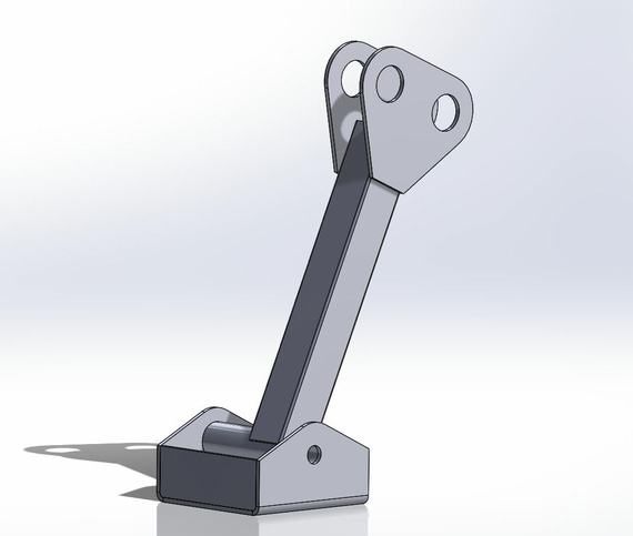
Aileron Idler Arm and Bracket
And then, back to the bellcrank hell. I had it modeled back in the days, and the "jog" bend 1/2 inches down made. Here's how busy the sketch with all the radii and holes looks BTW; pre-bending.
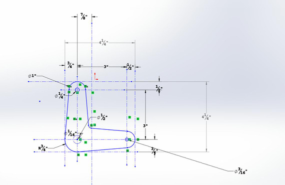
Bellcrank layout
Anyway, with all the sheet metal awesomeness SolidWorks doesn't know how to twist. You can twist a model by using deformation, but at that point all kinds of shenanigans begin to happen. For example, all faces of the model stop being planar faces (meaning nothing can be sketched on them, and sketch is how you start defining a feature (part of the model)); for some reason I wasn't able to put a reference point into the center of one of the holes, etc. (I ended up drawing that point finally by projecting that hole's centerline onto one of the faces; that did work for whatever the weird reason Solid Works gods must have).
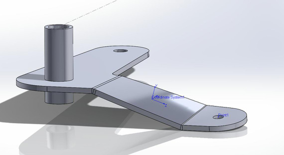
Bellcrank, bent and twisted
And after fiddling with it for about an hour, I was finally able to position everything. The plans don't specify where the bracket should be, so my educated and logical (yes, mr. Spock?) guess was that it should be so that the aileron pushrod connecting bellcrank to the alieron hinge is aligned and straight in the "aileron neutral" position. So I used the aileron hinge center as the reference; squared the bellcrank and aligned it that way. Note the blue line (that's actually a plane bisecting the aileron hinge), and the Point1 (that's that wretched point on the twisted surface that took me so long to figure out). That's what I used for alignment.
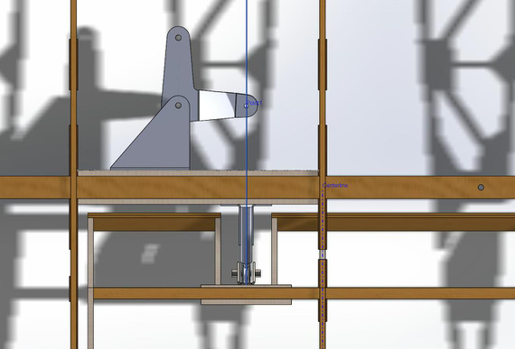
Bellcrank mated and aligned with aileron hinge
Coming up, putting in the idler, all the pushrods, and checking clearances with rib truss throughout the full range of motion. I strongly suspect that I will need the control stick's model on the fuse to do that, since that's what the other end of that pushrod attaches to. Oh man... gotta love those dependencies. That just means that I will have to do that model earlier than planned. Oh well. I like Solid Works anyways...
Tomorrow's the Shop Day! Gotta clean and put that compressor together.
OK 5:11 AM; time to go get some sleep :)
Flying is the perfect vocation for a man who wants to feel like a boy, but not for one who still is.
© Copyright "79FT". All rights reserved. Feel free to cite, but link back to the pages cited.
This website only shows how I did things in my various projects. These pages are for information and personal entertainment only and not to be construed as the only way, or even the perceived correct way of doing things. You are responsible for your own safety and techniques.