[79FT]: Building Things |
 |
Motor Start
...:)
| On: | Oct 15, 2020 |
| In: | [Chickenhouse Charger] Electrical Rebuild |
| Time logged: | 23.0 |
| Tags: | 6781G, MA5 Charger, FWF, electrical, engine, exhaust, alternator, fabrication |
And so, we're onto the race to the first motor run. I am writing this about a month later - according to the log, the motor was started up September 19, 2020.
But first...
Upfront
Finish mounting the starter was no problem: clean up the threads, clean up the studs, torque, done. Then, the alternator.
Belt tensioning... too annoying by hand, but it took me a while to stop trying and become sensible.
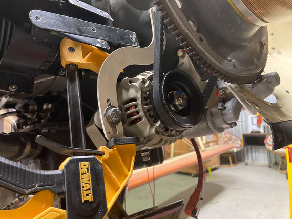
Belt Tensioning
You gotta safety two bolts over there, and I decided to make it nice: for the bottom (pivot) bolt, drilled a tiny hole in the bracket lower than where the alternator would be, and for the top bolt attaching the bracket to the motor... hmmm...
Somewhere on VansAirforce someone used a cherry rivet as a "hookup" point for the safety wire. I thought to one-up that, and use a short #8 screw - drilling it's head.
Frankly, I didn't think it'd work out.
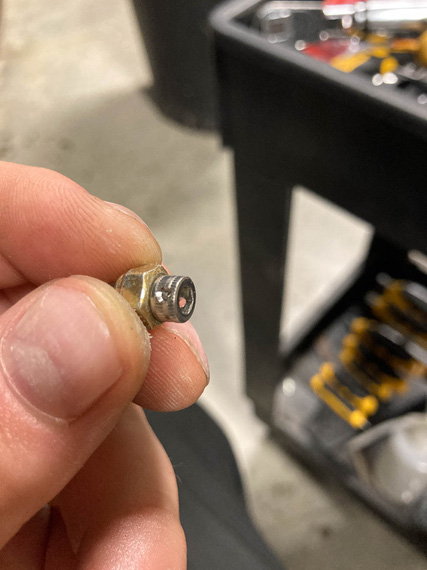
Drilled cap head
...but as you can see, it did.
So then, to the hole in the bracket. I needed a #8-32 tap.
Side, fun, story: quite a while ago I ended up bidding in a machine shop liquidation auction. Got quite a few nice things, including a very heavy duty bandsaw - and, accidentally, a massive cabinet full of tooling. Anything you could imagine: inserts, drills, taps, slitting saws, you name it. In all shapes and sizes. When we moved the cabinet, we emptied it into about 10 boxes, so ... I did have a #8-32 tap. In fact, probably about 20 of them. Question was, which one of the boxes were they in.
... apparently, in the one on the top. Hmm. This kind of luck is unusual.
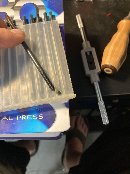
Tap
Look at it carefully. Does it look like a regular tap we are all used to?
Didn't to me either.
So to researching we went.
Aha! "Threadforming" tap. AKA "Cold Rolling". So that's how they're done. Rolled threads are formed into the metal rather than cut; giving them superior strength. Basically, the tap shapes the metal, displacing it in the valleys and raising peaks.
Company that made these taps was advertising them for CNC milling. Well, what's a human if not a bio-CNC machine?!
Okay, problem number 2. I was pretty sure normal tap and drill chart values for hole diameters won't work; making too small a hole. Hmm...
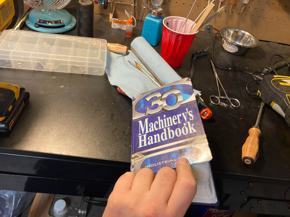
The Bible
Aha! "Ideal Theoretical Hole", and closest drill available charts are just what's needed.
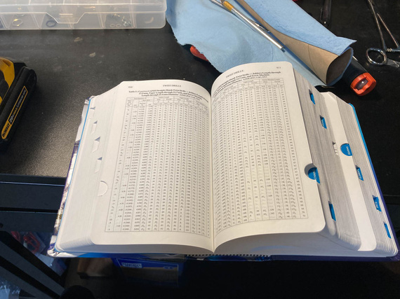
The Word
And with that, the affair was a non-event.
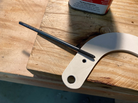
The Hole
Actually safetying was annoying - I had to try twice, because I had to use a hand-twister and you had to get the length just right.
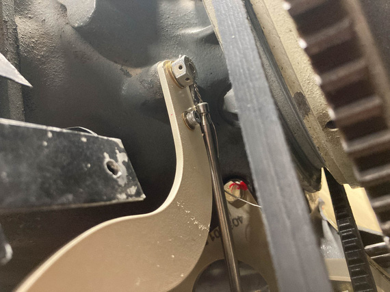
Hand Twister
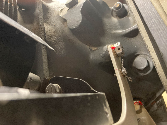
Safetied!
Airbox
That thing needed to be put back on, and carb final torqued with a new gasket. Cleaned it all up inside as much as I could, and had to cut a couple of special gaskets that I can't for the love of me figure out where to get (carb's base is different size from the top - and this is an "airframe" problem - read, "no standard part from Marvel or Lycoming I could find reasonably"). No problem. Used the same material Lycoming used for their gaskets, ordered from McMaster, and made me a couple.
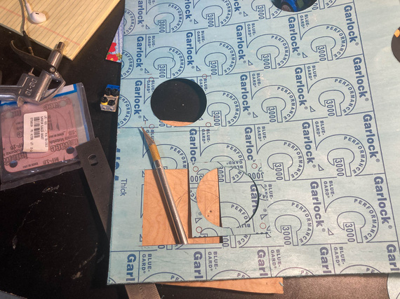
Cutting gaskets
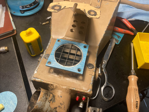
Where they go
Perceptive will see the "airflow straightener". Glenn had it on when he put on the Rotec TBI, and in the times of my research of TBIs, I have discovered that some folks claimed they helped on carbureted motors as well. Well, it definitely won't hurt - aside from my having to do two gaskets instead of one. No biggie.
Carb
One interesting thing that happened. I had to drain the carb bowl of all the preservative oil, and flush it, so I took off the plug, drained it, and started putting it back in. Plug's an NPT thread with torque listed by Lycoming in SSP-1776 at 144 inch pounds.
Hmmm.. I noticed it was going in way deeper than it was in before, and way "harder" than when I took it out.
Hmmm.. Well, it's Lycoming, they know what the hell they're talking about. So in it went, at 144 inch/lbs.
But this bugged me. I think some other day I pulled out the Marvel's manual. 25-30 inch/lbs?! WHAT?!
Back to Lycoming. 144. Marvel (the makers of the carb)? 25-30. Damn it. Forums? Nothing interesting.
I finally figured it out. In SSP-1776, in the table for special torques, Lycoming lists the plug to have 3/4 pipe threads. Mine were 1/8 NPT. Lycoming's torque for those is 40-44 inch/lbs. Still higher than Marvel, but much closer now.
So, I undid the plug, that cut a bit of the tapered thread "deeper", of course. And put it back in, with the right torque this time.
Other Stuff
And then, minor stuff here and there. Cleaned and prepped spark plugs. Put the exhaust back on. Tightened things that had to be tightened. Charged batteries. Tied up everything hanging loose. Gave the plane a good look all over.
We were ready for the final day. There were a number of things I needed two sets of hands for, and I had just the man lined up.
Day X - or, September 19, to be Precise.
My buddy Mr. N. agreed to help, and be my observer and fireman (just in case). Mr. M. was extremely inquisitive about how we're gonna be putting out a burning airplane, and I had to explain a number of times that the goal of an exercise of starting a motor that's been idle for a year is not to have it go ablaze, and having a fire watch nearby is a part of prudence, not expectations. He seemed to have been disappointed. I would be too, if I was 5.
So, on a nice Saturday, we went to the airport.
First, drained all the pickling oil. Took off the prop (because we'd have to spin the motor to pressurize the oil lines). Put the fuel pump back on. Tightened all new fuel lines, and leak checked them. Mr. M. used my fancy "button with alligator clips" to turn it on. Put new oil in, primed the oil cooler and pump (and this is fun in this airplane, because there's no oil filler neck on the motor). Checked control cable travel, and final cotter pinned them. Checked brakes again (though we bled them when I finished fixing them up).
Then, came the pressurization, and purging of oil lines, time. Mr. M insisted that he wants to "press the button" - which would put +12V onto the starter contactor; bypassing my normal starting circuit (latter would make the left mag hot, and I didn't want that).
I told him to press the button and hold it and not let go till I told him to.
Now, starters with a motor with removed spark plugs are fast, loud, and annoyingly sounding. Mr. M. pressed the button. Jumped a bit. Grimaced a bit. He clearly didn't expect it. I didn't see it, Nick told me afterwards - I was watching the oil line. I yelled "Stop" when I saw the oil come out, and looked at Mr. M - who, at that point, was shaking and at the point of breaking down in tears. But! He didn't let go of the damn button. Man.
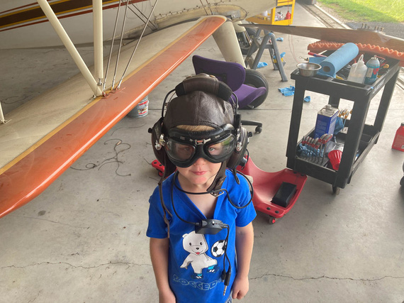
Mr. M
And that was that. Plugs went in, and we were ready, but broke for lunch, first. Mr M deserved his hot dog.
... back from lunch. Plane out. Wheels chocked. Brakes tested. Fire watch ready and instructed.
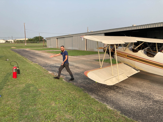
Final prep
... damn, that old Concord battery removed from the Cheetah years ago is weak and barely pulling thru.
... second try: no primer, so I have to pump the throttle a bit.
... she's alive!!!!!
I let the temps go up just a bit, and called N. He confirmed everything seemed to have been fine. We shut down, and went over every fluid fitting. All good.
Started her back up - I wanted to warm the oil to a reasonable temp and let her circulate for a bit, maybe 30 minutes - to get the juice flowing again.
On the second run, I revved her harder, and smelled something. Smelled like... burnt wiring? N. went around the engine, all wires, and everything he could see or think was close to being to a hot surface, or an electrical doodad. No signs of trouble.
We decided to proceed.
She ran just fine. I think we ran for about a total of 30 minutes. Shut her down, dragged her in. Went over the wires again - all of them. Nothing, all clean. There were no bad indications on any of the electrical instrumentation, either. So at that time, we left that as a mystery to be solved.
... and with that, we went home. We were tired.
Flying is better than walking. Walking is better than running. Running is better than crawling. All of these however, are better than extraction by a Med-Evac helicopter, even if this is technically a form of flying.
Up ↑
Brackets for Transducers
fun litte project
| On: | Feb 23, 2020 |
| In: | [Chickenhouse Charger] Electrical Rebuild |
| Time logged: | 5.1 |
| Tags: | 6781G, MA5 Charger, fabrication |
Pressure transducers. Those little doodads that take liquid pressure and transform it into electrical pixies on the wire...
The ones I got are from UMA. I'm replacing the mechanical engine gauge with electric - same 3-in-1 (oil temp, pressure, fuel pressure); but the fluids stay under the cowling. Pixies run in the wires to the gauge and rat those fluids out to it.
Ahem.
Well, this was always a part of the plan:
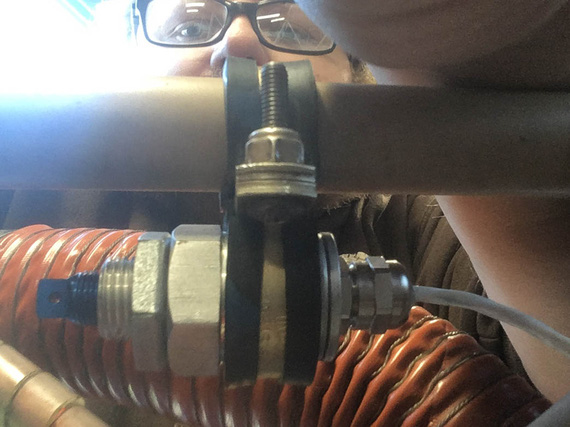
Pressure transducer on adels
but this never felt like sufficient. Only rubber (will harden up pronto) and screw torque (well, not too shabby, but still) prevent it from rotating. Plus, a single point of failure - and I am probably over too sensitive to a probability of dangling fluid hoses with transducers at the end under the cowling in flight.
No sir, we can do better!
Long time ago, I have installed a CGR-30 onto my Cheetah, and back then I mounted the transducers on two adels - but those were different style transducers, much longer than the ones UMA makes.
But they have that threaded "neck" and a nut on it.. hmm... Let's see if we can make some kind of a bracket?
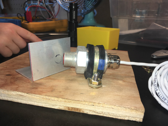
Marking the hole
Start with our good old friend aluminum angle. Now, the "tab" on the bracket will screw with another adel on the motor mount; that was the idea (so the bracket basically was replacing a second adel around the transducer that didn't fit). Therefore, the tab off of my bracket would have to be co-planar with the adel. It did not have to be super precise - I figured, 1/32" of mistake was fine.
A bit of black sharpie transferred the imprint quite nicely.
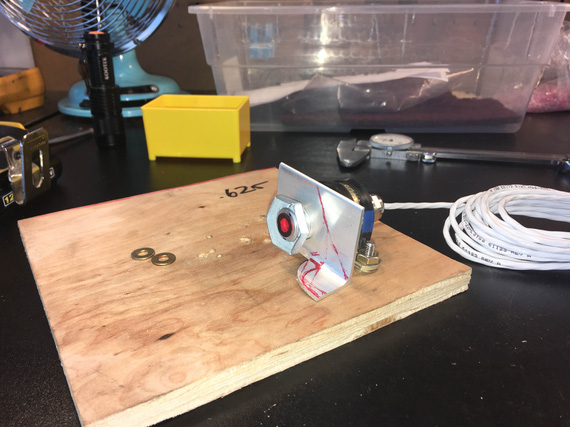
The bracket taking shape
And then, bandsaw and sander. Had to break out my good files to clean up the "fillet" that remained after cutting off one side of the angle under the nut (otherwise, the nut won't fit).
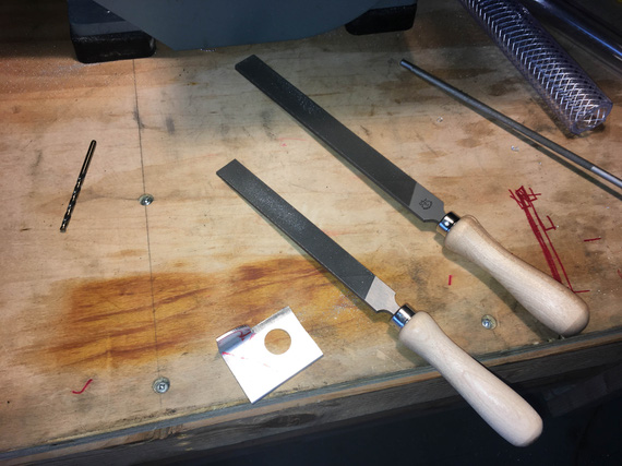
Pferd and Grobet, the two buddies at work
OKay, now, let's add a bit more fanciness to it. Using the nut to draw out circumference and to make sure to stay well clear for now
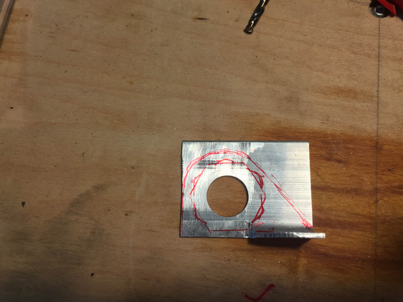
Now, make it "flow"
This above picture also shows the filed area real well - bottom left.
Finally, need to drill the hole for the adjoining adel in the horizontal portion - that one needs to be somewhat precise too, if the transducer is to sit straight. So, we'll test mount it on one adel, and mark out the second hole using the second adel.
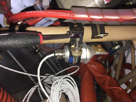
Marking hole location
Okay, drill it, and then clean up, deburr, round over all the corners, yada yada - the usual drill.
Tadaa!
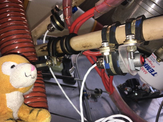
Jack likes the bracket very much.
But we have another transducer. That one's bracket will have to be "mirror image" of the first one.
I used the first bracket to kinda "estimate" the second.
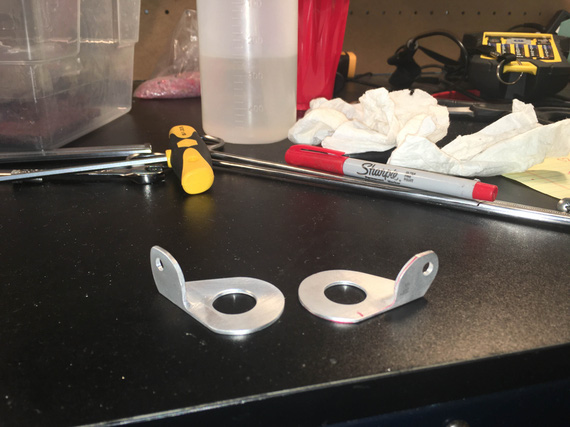
Now, both brackets.
Are they the same? Hell no. But I wasn't trying to make them the same. Just close enough to do the job.
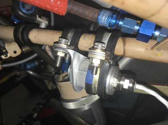
Second, fuel pressure, transducer
Fun little Sunday project, and I broke in the new fancy files :).
A kill is a kill.
Up ↑
Alternator Pivot Arm Bracket
lots of grinding
| On: | Aug 31, 2019 |
| In: | [Chickenhouse Charger] Electrical Rebuild |
| Time logged: | 14.5 |
| Tags: | 6781G, MA5 Charger, alternator, 4130, fabrication, drilling, CAD, SWX |
With baffle support bracket done, the next step on the path to alternator happiness was the pivot arm.
The Problem
... was that the default B&C's pivot arm did interfere with the front baffle hookup brackets.
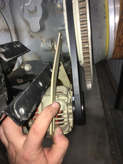
Interference!
That did actually make me pay attention to the very unusual old pivot arm.
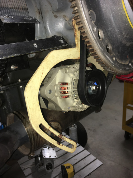
Old one
Nice dogleg, isn't it?
Well, this bracket did not involve any bending, just needed to make the correct one to fit around all the other stuff there on the nose.
Hmm... so how do we do that? Well, first, we need...
The Template
This is not the real template, because (.. read on ;) ). It's the template for the Template.

Start with a piece of heavy paper

Cut around the alternator
All we need to do with this template is show the location of the hookup hole (top hole, the one that attaches the bracket to the motor); the location of the slot for the alternator to hook up to, and the general outline of the alternator

Alternator bolt location is being marked
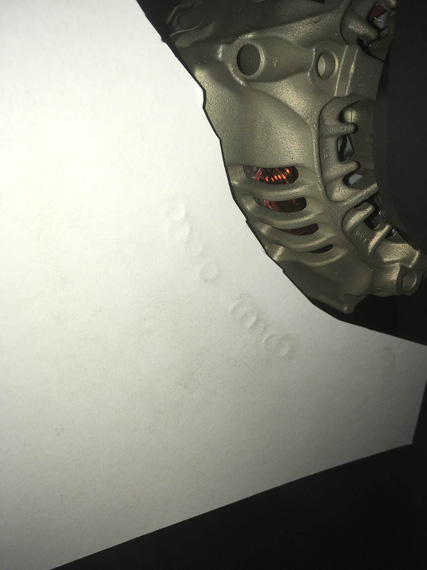
Bolt imprints along the "pivot arc"
..and finally, some more "no go" zones to prevent interference with other brackets there:

Done!
Notice I also added some "imprints" of the B&C-supplied pivot arm in there, just in case I'd need them.
Okay. I'm lying to you. This template is not the one I used. It was done with the long belt that ended up not working out, so I had to redo the template (thanks God, just the template). The new one was done in the same manner as the one I described above.
Here it is:

The *actual* template used
Okay. So now, we know critical locations of things and where not to go - so, cue in...
Solidworks!
It's magic, I keep telling people.
So, we take our template, and scan it on a scanner, along with a little metal ruler to give us physical dimensions. Then, we go to Solidworks, start a sketch, and insert the scan as "sketch picture". Using the image of the ruler that was scanned in, we tell Solidworks what "one inch" on this picture is. Boom! The image is now dimensionally accurate.
Then, we start drawing around it.

Initial sketch
Above, I positioned the top hole, and the four 5/16" holes around bolt imprints. I then sketched a large circle and made it tangent to three out of four of those holes - it defines the "pivot arc". Then, offsetting it 5/16th gives me the other "side" of the slot; and offsetting it more gives me the "sides" of the bracket in the "pivot arc" area.
I also started sketching the "no go" lines around the top portion of the bracket.

More circles
More circles and lines are added, and off-set. They are not positioned or dimensioned - just made tangent to "no go" lines. You can almost see the outline of the pivot arm, yes? ;)
Now, we take this master sketch; and add arc elements with real lines that we care about.

The arm!
Tada! We got the Solidworks Part.
By the way. How do you "measure" the round over of the B&C arm? Radius gauge? Calipers? Hmmm.. Or...
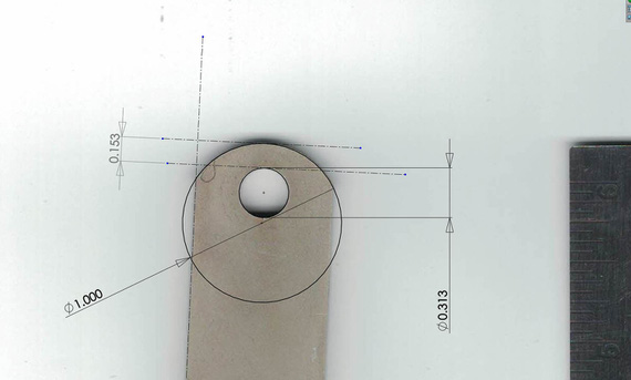
Measuring with Solidworks
Nice, isn't it?
Next, we print the drawing of our new part; making sure our holes' centers are marked (we'll use that later to drill them)
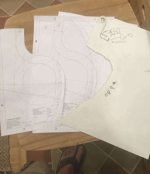
Done!
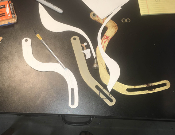
And, we got ourselves the actual template!
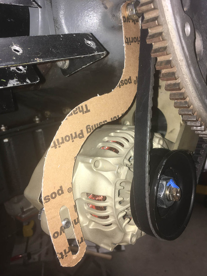
Now, the final test (Many thanks to USPS for providing material for this test)
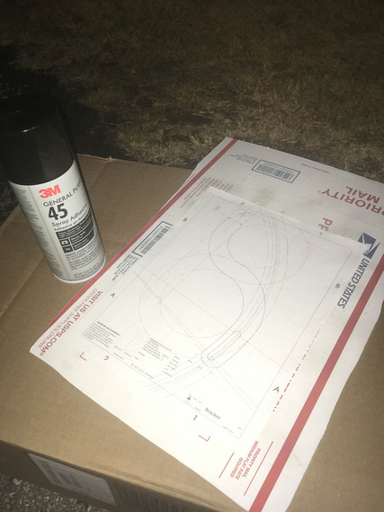
Spray glue and cardboard
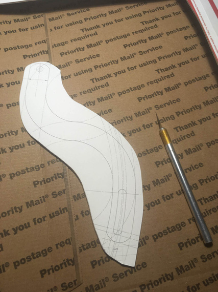
I wish I could cut 1/8" steel with X-Acto...
The mockup
Tadaa!!
Okay, we have the real template now, and we know it'll work. And now, comes...
The Grind
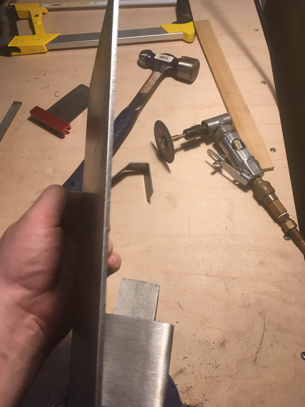
1/8" steel is no joke
Nice little sheet of 1/8" 4130 showed up from Spruce some time earlier... I used spray glue to put the print out of the bracket on top of it.
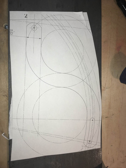
Template on steel
First, all the holes had to be drilled. The drill press I have at the moment is severely underpowered, so I had to step-drill them in four steps.
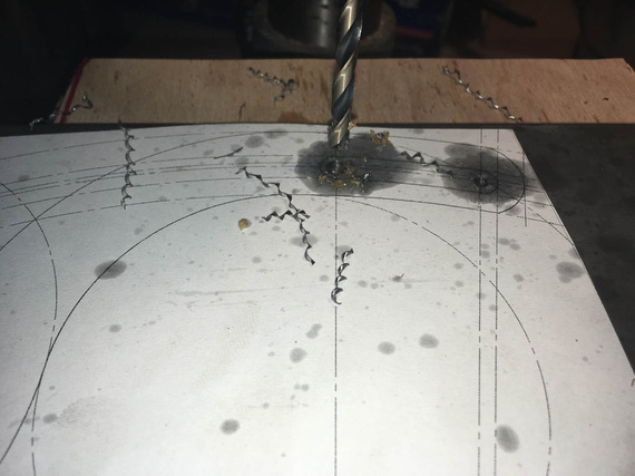
Curlies!
I got to admit, I am starting to become very fond of pretty steel curlies made by nice drill bits.
Also, lesson number one learned: drilling oil (I used TapMagic) gets under the template, and messes up the glue (and unglues it). I need to figure out a better glue.
I drilled the slot's "start" and "end" holes slightly undersized, and reamed the main attachment hole to 5/16ths exactly.
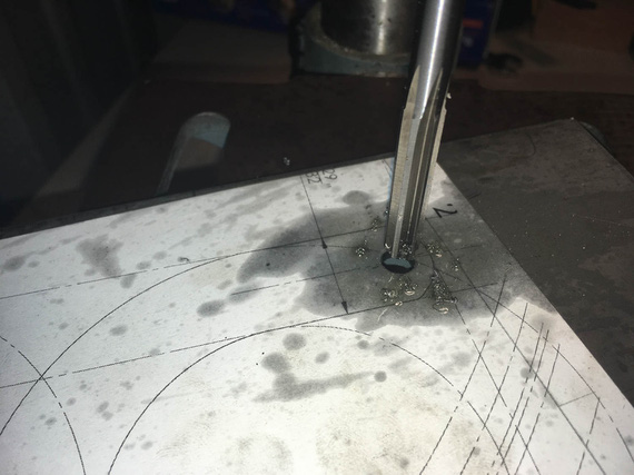
Reamer!
Next, the slot... I rough-drilled small holes around it's perimeter, thinking that a 1/8" shank carbide burr in an air die grinder (basically, Dremel) would work... Ha! It did... for a second ;)
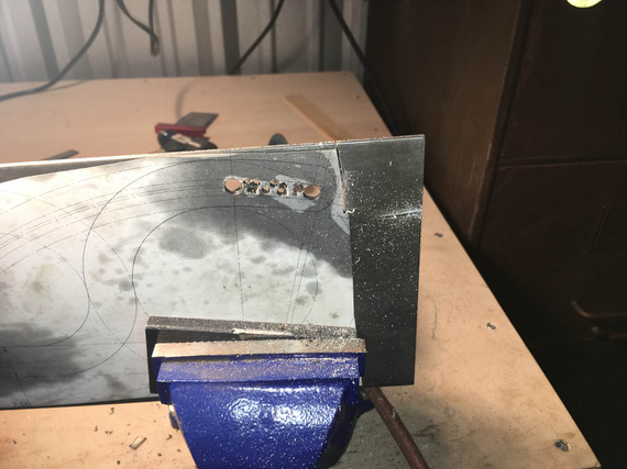
Slot in the making
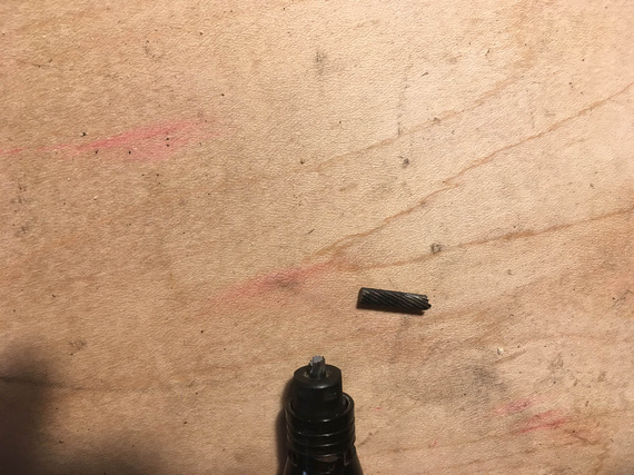
Boo!
Okay, time to go old school... where's that...
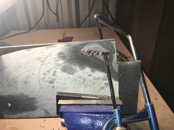
Hacksaw!
I cut it out, and cleaned it out with a bastard file.
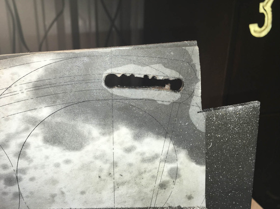
Cut out
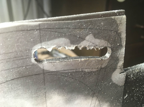
.. and cleaned up
And then, more and more hacksaw...
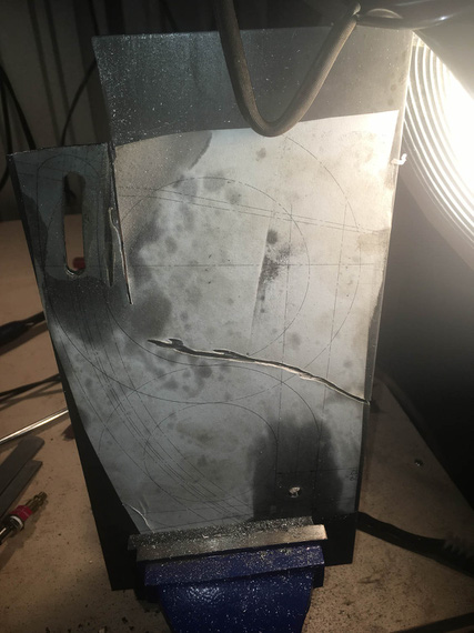
.. my right arm
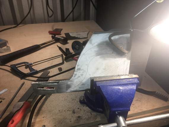
.. is beginning to feel...
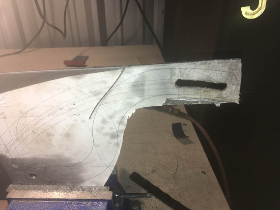
.. it ..
Yeah. The last few inches, I gave up, and used the jig saw. It did cost me 3 blades, but I was too ... done with the hacksaw. I figure, about a blade per 1 inch of cut in 1/8" 4130 with a jigsaw...
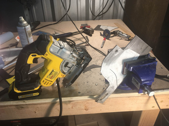
.. gave up.
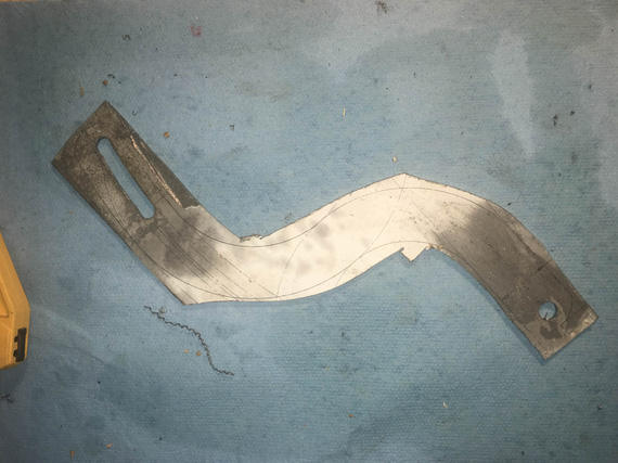
Cutting done.
Looks very ugly, right? Well.... to the grinder!
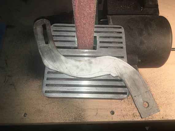
Grind...
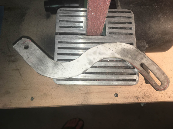
.. grind ..
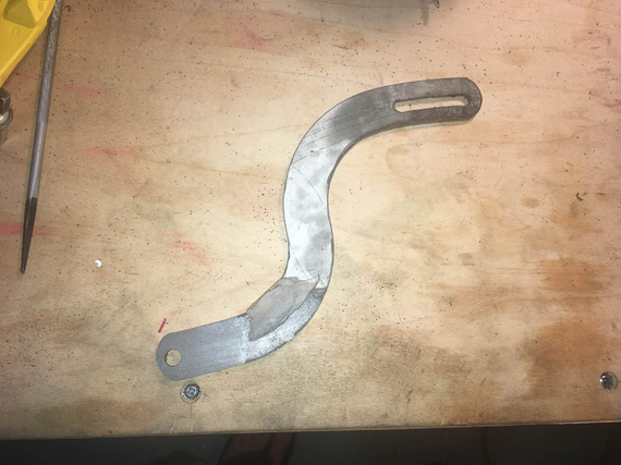
.. grind away ..
Three belts I believe is what it took.
Well, now, the final cleanup on the slot. Yes, Dima, I used the rotary file here :).
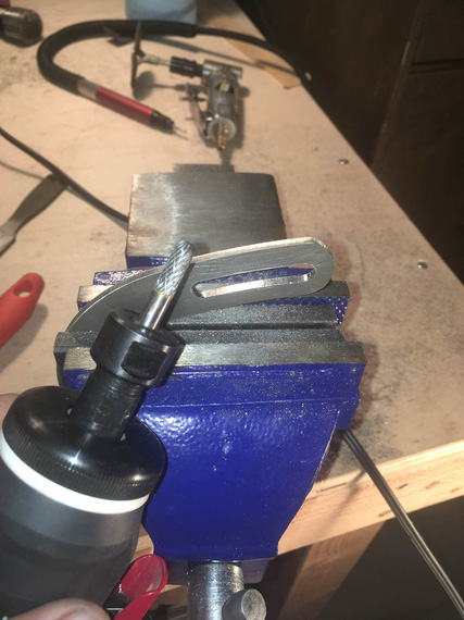
Cleaning up the slot
..and, test fit
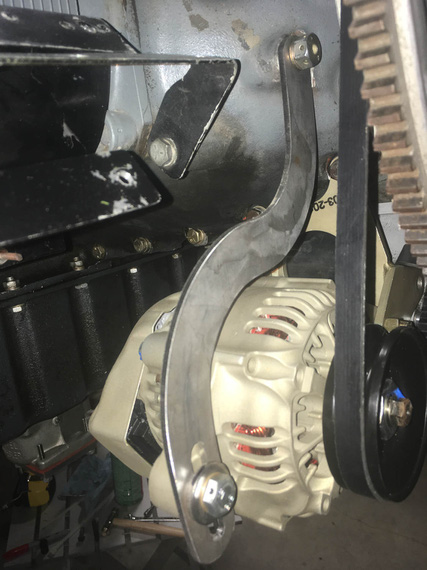
Tadaa!
That was two evenings, folks; but I wasn't done.
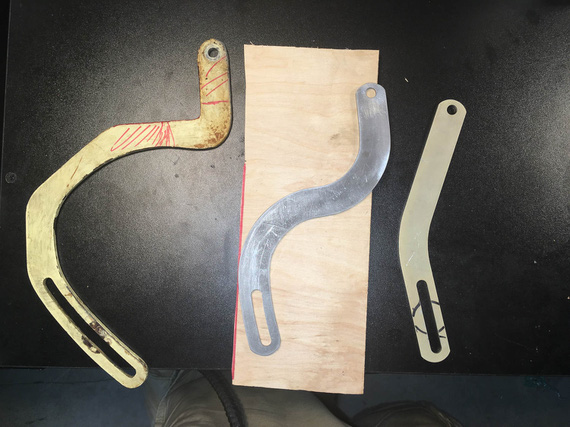
The Three Brackets
Next, I had to prep the edges and sand out all the scratches, and paint. A deburring wheel on a bench grinder helped; and the most nasty marks were filed out and then polished out with the deburring wheel.
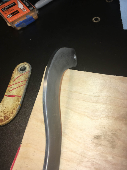
Clean edge
It has to be done because every scratch is a stress riser - on fittings, every edge needs to be rounded over, and polished.
Finally, to....
Paint
Every airplane "paintjob" I've done so far was in my makeshift "paintboots". Like this one.
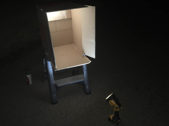
Paintbooth!
I sprayed both the pivot arm, and the baffle support bracket I made earlier, with self-etching primer, and some Rustoleum paint. White will make cracks more visible, if they show up.
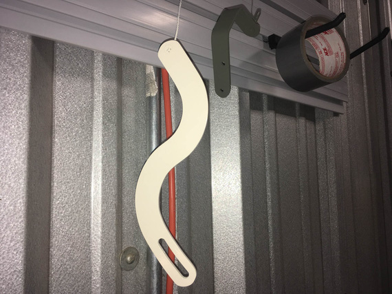
Painted!
So there we go. With this done, I can now install the alternator. Just measly 30 hours to get ready to install the damn alternator! ;)
"Citation 123, if you quit calling me center, I'll quit calling you twin Cessna."
-ORD ATC
Up ↑
Alternator Install: Nose Baffle Support Bracket
...I am Bender, insert girder
| On: | Aug 25, 2019 |
| In: | [Chickenhouse Charger] Electrical Rebuild |
| Time logged: | 9.5 |
| Tags: | 6781G, MA5 Charger, alternator, 4130, fabrication, bending |
As I have thought before, I would need the new nose baffle support bracket, to replace this one:

Old baffle support bracket
...because it would have to now be shorter, fitting in front of the new case mount alternator bracket, over it's right "ear" over here:
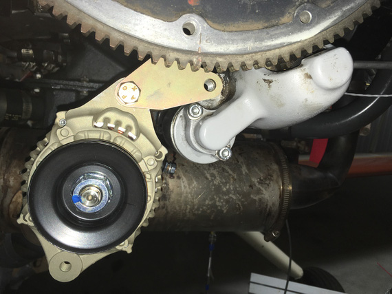
Alternator mount ear and starter
However, prepping to set up to do it, I found this.
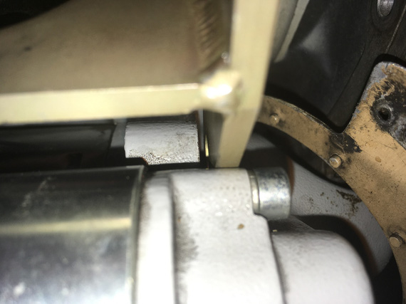
Gap between starter boss and alternator bracket
See that gap between the starter boss "ear" and the new alternator bracket?
Hmmm, methinks.. Maybe, maybe, I can get away without bending up a new, 0.090 steel bracket with weird geometry (it's not a simple "couple bends and you're done" - you'll see later).
Well, let's see.

Old bracket fits nicely in that gap
But it was just a touch too "low". Didn't fit right - and I couldn't raise it (that would raise the holes to which the nose baffle itself attaches, and make the whole thing just not work).
Oh well, I guess we're bending steel after all.
Around that time, my strip of 4130 I ordered from Spruce some days back showed up.
I needed a vice, and a couple more pieces of steel for bending block and such. Picked those up at big box stores (and I will admit, that included a trip to Harbor Freight..).
I also fished out my old small belt sander, and air grinder, from the storage (all my tools are packed up aside from simple hand tools - I am rebuilding my shop; and thanks God I had them close so that I didn't have to rummage thru boxes).
Cutting off a small chunk of an approx. 1/4" thick strip for a bending block is no joke...

... Cutting
My compressor would run out of air, and I'd have to stop, and, while waiting for it to get back to pressure, use hacksaw ('cause I didn't have anything better to do).
Then, I attempted to get away with shoddy bevel grind on the bending block...

Very poorly made bending block
I hoped that that little "cavity" in the middle would work enough to handle bending spring-back - the roundover was fine, just the bevel was uneven.
Ha! Bending a couple of test bends proved me wrong; and that one never gets away with shoddy workmanship.
I re-ground the block to have a nice, even section (all that on a 1x30 belt sander by the way - which I have discovered is perfectly adequate for handling steel with a ~40 grit belt).

A much better bending block
Cut my 4130 strip to width:

Hacksaw!
... and clean up that edge

Edge to be cleaned up
I kinda gave up on it, frankly - got too tired to get it straight and even; and decided to temporarily switch my mind to something else.
Instead, I cut another, test strip, of 4130, without making it to proper width - and attempted to replicate the bracket's geometry on the now much better bending block.
Thinking about how to replicate bend lines, I couldn't think of anything better than... just roughly folding a piece of paper over the old bracket.

Old bracket, test bend, paper pattern, and strip prepared for the new bracket
It worked!
The key was, rather than bending the strip over the block by hand, instead, start the bend by hand, and then finish it with the hammer. I used another piece of 1/4 strip that I cleaned up as an "interface" between the hammer and the material bent, to avoid hammer marks. This way, the bend was much tighter radius (equal to about material thickness, which is what you need for steel), and much easier to control and nudge in the proper direction.
The geometry of the bracket was close enough; the angles were off a bit, but those could be tweaked.
All that bending was one day. I felt done, and left.
Next time I was over at the hangar, I thought, "to hell with it", and decided to use my real strip that I cut out for final bracket.
Used a nice square to draw a reference line, and cleaned up and straightened that edge left over from cutting, marked the first bend line using the paper template left over from my test bend:
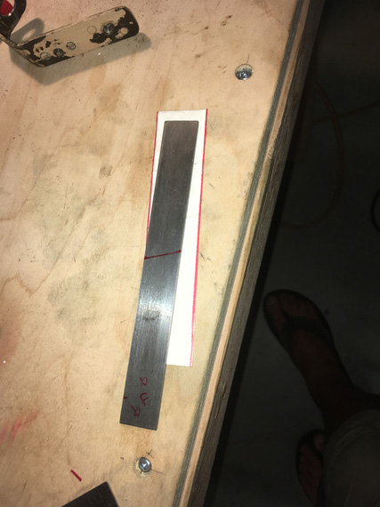
Bend mark one
... put it into the vice

Bend one
and bent, using the old bracket for angle reference. That worked out okay, so marked and bent the second bend

Bend two
See the problem? Yep, the first bend is not right on the mark - I did not clamp it right for that first bend. No problem though, I had enough spare length on both ends, so I just moved the location of the second bend accordingly.

Final tweaking by hand

The hole is made, the "ear" is about to be
The hole was drilled with a Unibit, and all the cutting off of small pieces was done with a 3" cutoff wheel on an air die grinder, followed by final tweaking on the 1x30 belt sander.

The ear
And now, the first try.

Did it... work!?
Wow. It might've worked!!! Maybe.. just maybe.. the final test will be if I'll be able to make the holes for the baffle in it.
But for that, we need to position the baffle, and then mark out the holes.
No problem.
Bolt on the old bracket, and hook up the baffle to it. Use anything, whatever, for reference (I used the starter conveniently sticking thru the baffle):

Reference marks set
Then, unbolt old bracket, put the new bracket in, and mark out the holes, while having the baffle back to position marked by reference marks.
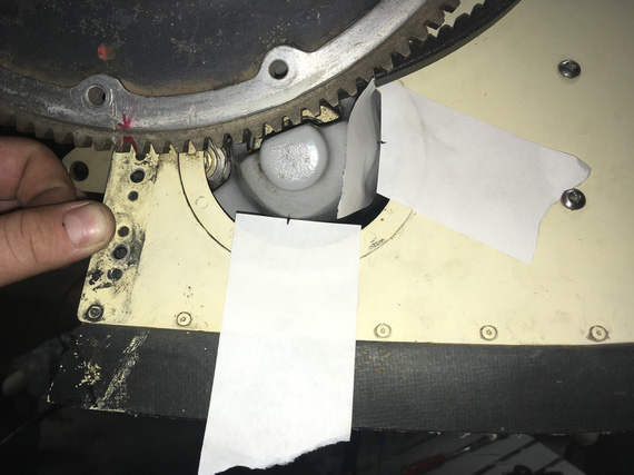
Marking new bracket
Okay, here it is. The final test.

The Two Brackets
Not bad! Given the messed up geometry, me using the paper pattern, my first attempt at bending, it's not that bad at all! Hey, my holes are also not on the center; but the old bracket doesn't have it's holes particularly centered either (and it won the Golden Lindy ;) ).
I guess I'm keeping mine.
I pulled out my nice Cobalt bits I got at Oshkosh to make those holes. At that point I have obtained an old small drill press for the hangar (I had to drill the first, large, hole in the "ear" free hand - even with Unibit that was very annoying).

Sweet metal shavings

Final check

... and, trimmed to size
Emery cloth the whole thing, and it's done.
By the way - you must say - but it's just two bends! How come your holes are not lining up nicely, and such?
Well, this thing has a very messed up geometry. It's two bends, at a non-even angle. This picture probably illustrates this best:

Geometry
Meanwhile, I also had to figure out the alternator's belt length - to make sure it clears all the brackets, and holes in the nose baffle.
I wrote a bit about it in the previous post. Initially I thought that just mocking up the belt, measuring the length of the mockup, and ordering the right size would work - ha!
New belt was too long, and didn't clear the newly made bracket.
Ooookay. Well, I had the belt that's too long (the one I ordered after making the mockup of belt length with a chunk of wire). And, I had the belt that was too short (the one that came with the alternator).
So, I bought all the sizes in between.

Belts!
The one that worked? 7320 :).
... and just to make sure that everything will fit with the new bracket, I ended up putting the nosebowl back on. Didn't want to discover that the nose baffle was sticking out, or not fitting in any other way, when putting the cowling back on.

Bracket - final cut (still temp hardware)

Fit check with nosebowl
OKay. Next - the pivot arm! No bending here. Just lots and lots of grinding.
Meanwhile, all my electrical hardware started showing up! It's like Christmas in August!
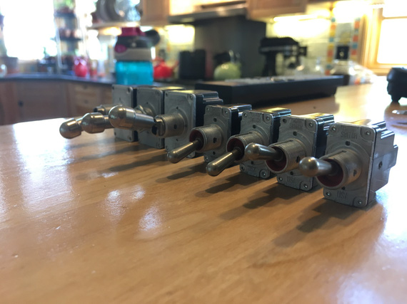
Switches
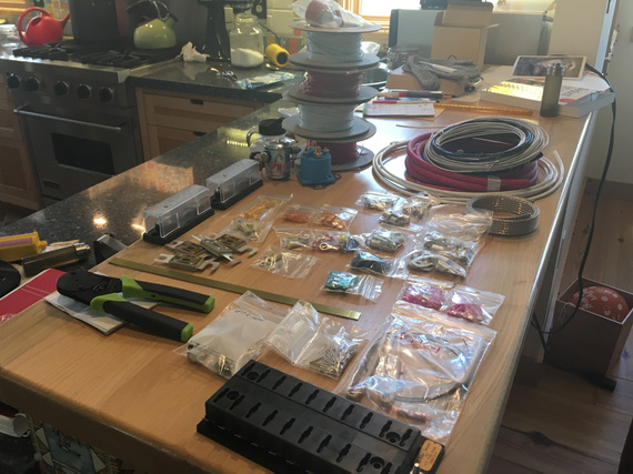
Components
If you push the stick forward, the houses get bigger, if you pull the stick back they get smaller.
© Copyright "79FT". All rights reserved. Feel free to cite, but link back to the pages cited.
This website only shows how I did things in my various projects. These pages are for information and personal entertainment only and not to be construed as the only way, or even the perceived correct way of doing things. You are responsible for your own safety and techniques.