[79FT]: Building Things |
 |
Brakes and Wheels
fixin' and bleedin'
| On: | Nov 04, 2019 |
| In: | [Chickenhouse Charger] Electrical Rebuild |
| Time logged: | 23.1 |
| Tags: | 6781G, MA5 Charger, Annual, brakes, wheels |
So this one turned into a month long project, give or take. Sure, sure, I was doing other things, too: last one of which was completed October 9th... after which I was finishing this one exclusively, pretty much.
Damn. One month to finish putting the brakes together. Granted, I had a hiatus for a week and a half, dealing with fixing up bad (non-aircraft) plumbing and cutting (non-aircraft-grade) trees.
Regardless... Shall we?
...
After having finished making the new brake line, I naturally wanted to install it and call brakes done.
Some of the disassembly work documented here actually happened prior to the new line being bent up, but hey. Putting it all in one place makes for a better narrative in one context.
First, the Calipers
... one of which was cracked due to someone having overtightened the bleeder adapter. Oh well.
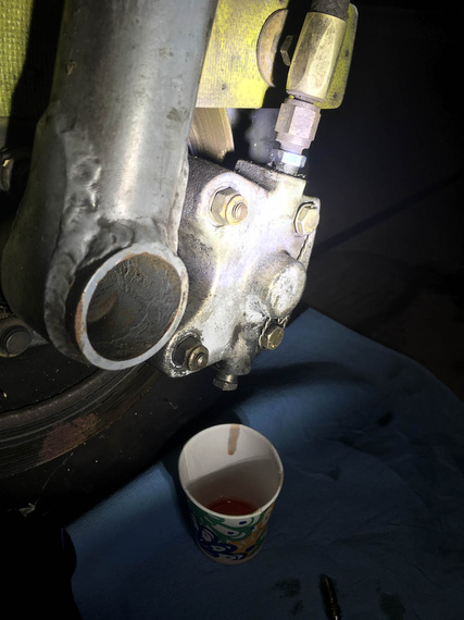
Drain
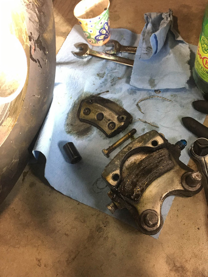
... and pull
Brake pads were soaked in brake fluid. For that matter, the disk was covered in brake fluid that hardened to molasses-like consistency (which mineral milspec fluid does, apparently).
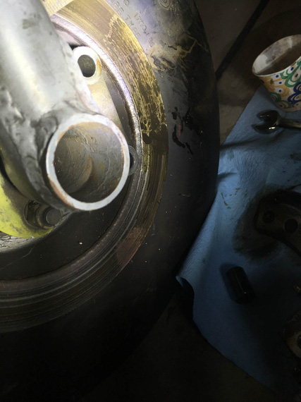
Ugly smudge
Intermission. By the way, it seems that this smudge didn't come from the dripping bleeder, but rather, judging by how the pads were soaked, from under the brake piston. Probably the o-ring was bust, and it was weeping from between the caliper and the piston. It seems that it had been a feature of the plane for a while.
Jumping a bit ahead of myself, on the other side, I discovered the brake disk somewhat dirty with oil - crankcase breather hoses are routed into the _left_ side wheelpant and terminate near the disk - clearly, spraying a bit of oil on and around it. You'll see those hoses on the pics of the left wheel below.
I think Remo's idea was to prevent oil on the belly from the breather. My friend's Ben contention was, this was a brake lock-up prevention measure; and when he brought it up, I immediately realized... leaking piston on the _right_ caliper was a lock-up prevention measure as well - to make sure both brakes are equally slippery - right one with brake fluid, left one with motor oil... At any rate,..
I will admit, this was my first caliper job ever, and anchor pins presented a bit of a problem. They're press fit in the caliper, and I didn't have an arbor press. Well, I used an old 1/4 nut that I banged on (gently!), and finished with a drift punch....
Tappy-tap-tap!
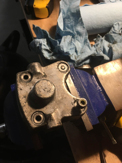
Tapping out the pins (aka anchor bolts)
With the caliper put apart, I tossed the old body, and took maroon scotch-brite to the rest of the pieces to clean them up.
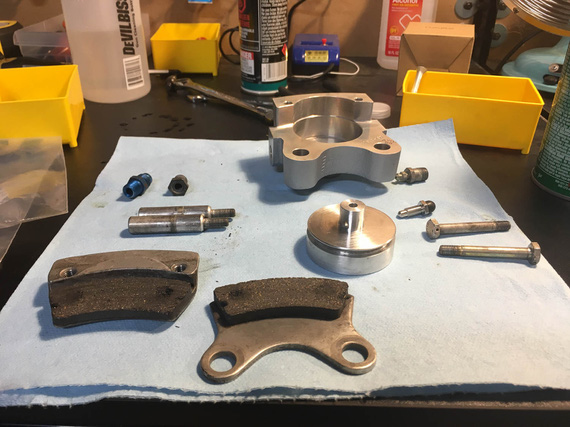
Cleaning up the parts
Now, I tried tapping the anchor pins back in, but was too afraid to mess them up. Finally, that was an excuse to go get me an arbor press!
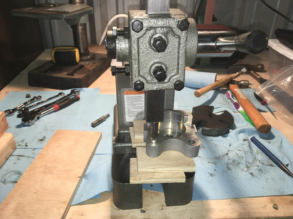
Pressing the pins back in
One final bit was to put the nuts back on.
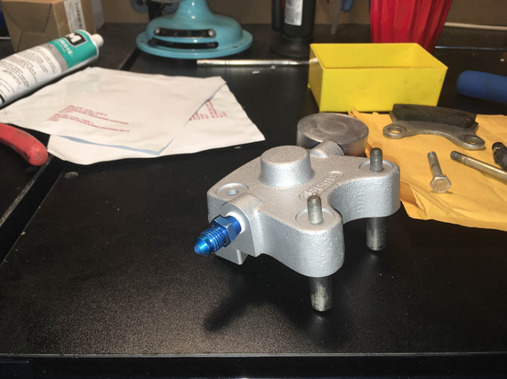
Ready for nuts
Question: how many wrenches does it take to put on an aircraft grade nut properly? Answer: three.
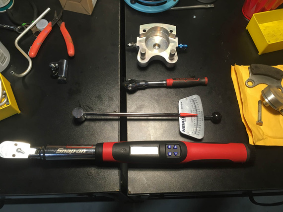
Wrenches!
Answer: three. Ratchet to work the nut before it's torqued. Small torque wrench to determine the free torque. Large torque wrench to torque to spec.
I pulled off the other caliper, and cleaned it up, too.
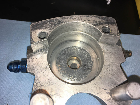
Left caliper, cleaned
Put in new piston o-rings, cleaned up AN flare adapters, put the calipers back together, and put them away.
Next step was,
The Parking Brake Valve
That little doodad was leaking for a long time, too. It seemed it was leaking from the little cam arm that rotates, but I wasn't sure, so I decided to put it apart and rebuild it completely, too.
It's under the passenger's seat on the Charger.
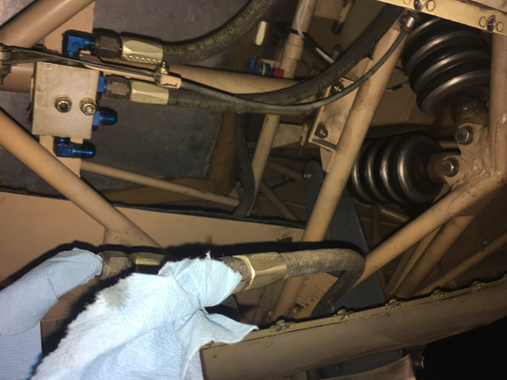
Pulled it off
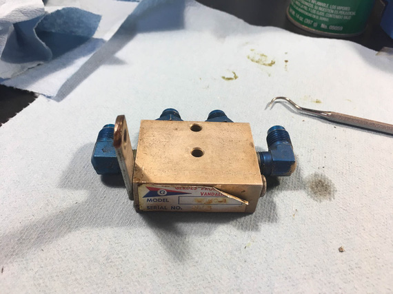
On the bench
First, I pulled the "cam arm" out - the little arm pivots, and pushes valves open (or lets them close) inside the box.
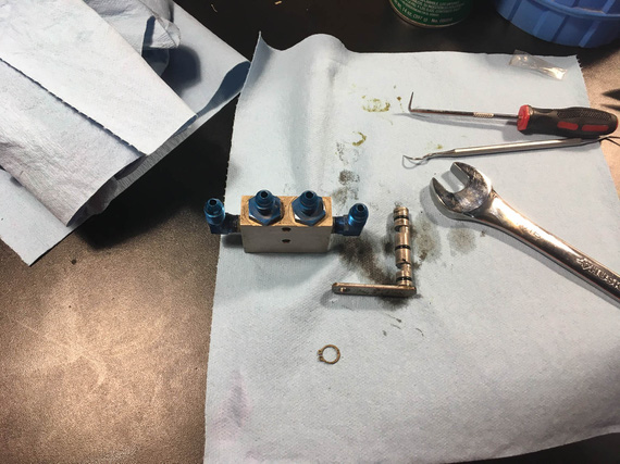
Cam actuating arm
O-rings were in reasonable shape, but looked a bit.. old. I decided to change them and disassemble the rest of the contraption, to change all the other o-rings in it.
Now, the middle two "straight" fittings are straight threads and o-rings under them. No problems there.
The two 90 degree elbows on the sides are NPT. One came out just fine. The other... Well, the other decided to leave a chunk of itself inside the valve body...
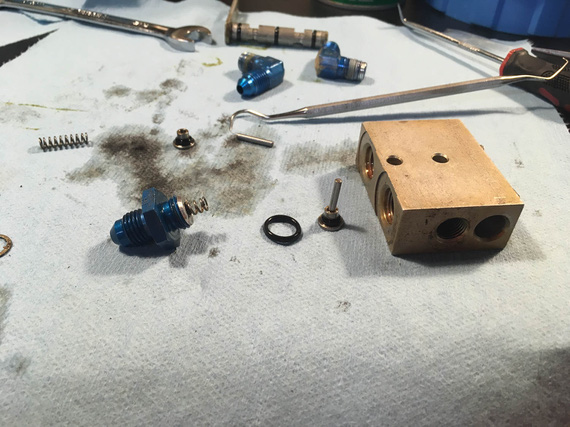
Bits and pieces - valves, springs, and actuator plungers
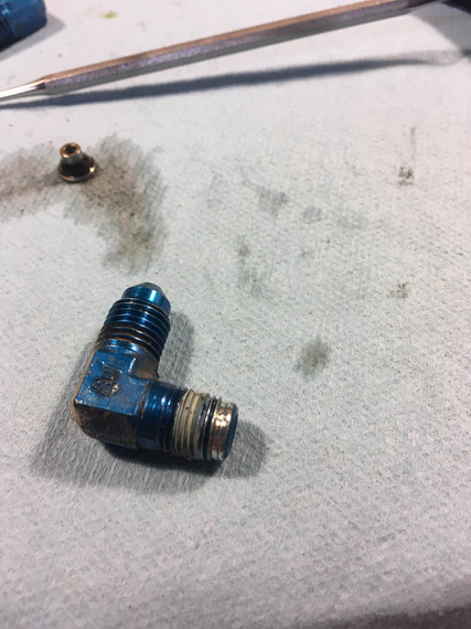
Busted elbow
You can see the chunk of the male thread galled and stuck in the female NPT hole of the body.
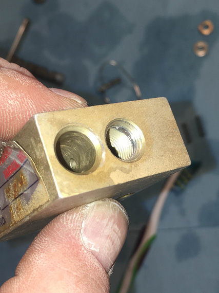
Chunk of thread
Damn damn damn! I need a new parking brake valve now?
That new valve is how much (search.. search.. six hundred and sixty five!?!?!?!?! $#*@(&(2@@#!). No way I'm paying that.
There are alternatives. Cheapest one is like what, hundred fifty bucks; and I'll have to work around it's plumbing (which is different than mine); and the "direct fit" "homebuilt" cheapest one is over $300? No way. No way in hell until I try to fix this.
What is the hole? 1/8 NPT? McMaster sells taps for $25, two new fittings are what... under $30, and a handful of o-rings, which of course I didn't have (I have a bunch of o-rings in a ton of sizes for fuel applications, but not for brake applications).
We'll try to re-tap that hole; hopefully braking the piece of the thread left in there by the fitting while keeping the female thread intact...
... the tap and the o-rings got delivered a few days later. Made myself some nice soft jaws for the vice to hold the thing without scratching it.
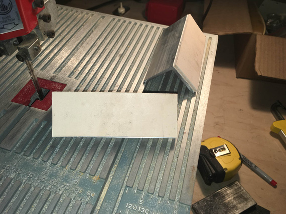
Soft jaws
That's aluminum angle and leather.
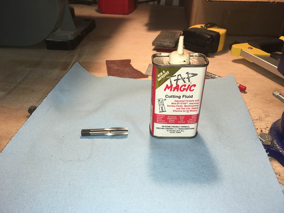
Weapons ready!
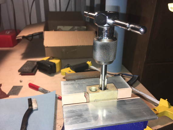
Tap, tap, tap (not that kind of tap!)
Slowly, slowly and gently, breaking the chip every 1/4 turn and adding cutting fluid. It worked out great! The hole was deeper than needed, so I tapped the threads a bit deeper, arguing that if the female portion of the threads got chewed up a bit, I'd put a fresh surface on them too.
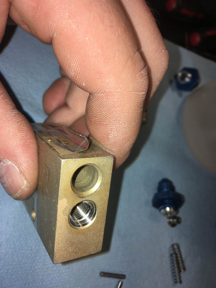
Done!
Well, we'll have to wait to see how well this works out. If it doesn't leak, I just saved me a boat-ton of money.
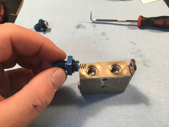
Putting it back together
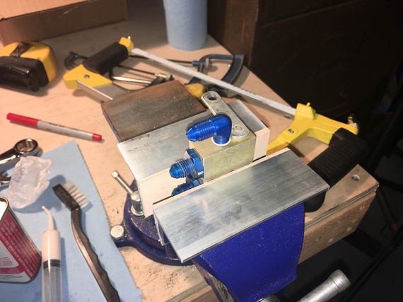
All done
New o-rings, new elbow fittings, re-tapped hole. Threads on the busted hole felt good, no hesitation and "catching". We'll see how that works out...
Next,
The Pads
Pads on the right brake (the one with leaking piston o-ring and busted caliper) were soaked in brake fluid. Cleveland says contaminated pads are a cause for replacement, so I decided to do it, since I was already in there. Besides, excuse for another tool - this time, the brake rivet set!
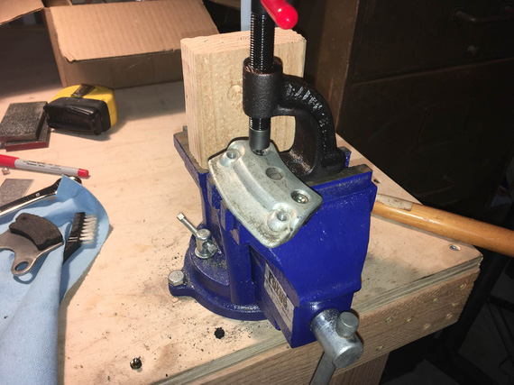
Punching old rivets out
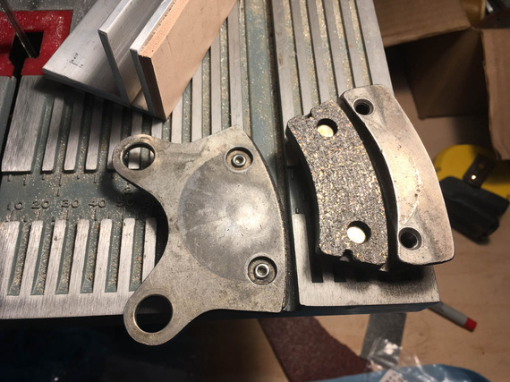
... and putting new ones in
And with that, the last bit before we could put everything back together was,
The Wheels
Again, since I was already there, I decided to do the wheels at this time too - re-pack the bearings, that is, and give the disk contaminated with brake fluid a real good cleaning.
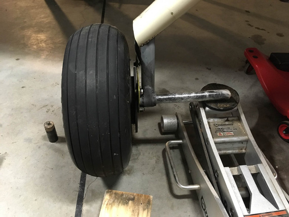
Jacking the plane
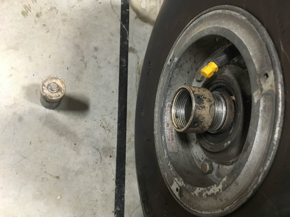
The axle nut comes off with finger pressure
I admit - I made a mistake here. I did not remember what kind of resistance I felt when spinning the wheel on the axle before I took off the nut and took everything apart. It would've been important, especially since this was my first time doing these wheels, and wheels in general....
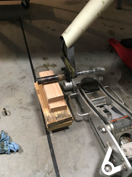
Temp "wheel"
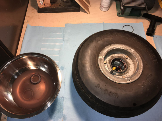
Cleaning bearings
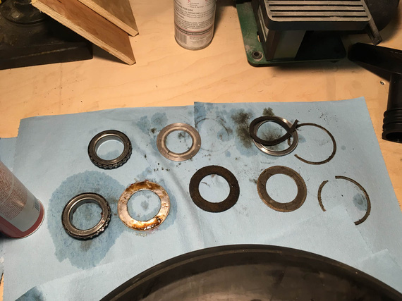
All the grease seals (and bearings)
Crap! What, the felt seal is bust!?.. Looks like it is. Okay, not finishing this part quickly (because of yet again, another "order parts / wait" cycle).
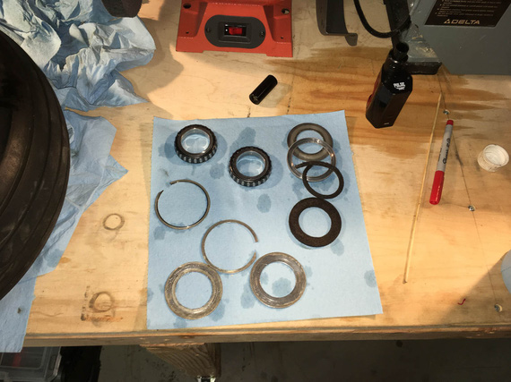
Flushed, and drying
Do you see the other mistake I made? Yep. I mixed up the bearings ("front" and "back"). Bearings should always stay with their races...
Oh well. After some research, seems that the worst that will happen is wear will get accelerated.. since the bearings and races looked squeaky clean, I decided to keep them as is.. for now. And just Hail Mary the position (since I have a 50% chance of getting it right :)).
I decided to replace all the felts because I was changing grease from I didn't know what kind but likely red Mobil grease to Aeroshell 22.
Ironically, I apparently didn't take a single picture of the bearings being greased - probably because my hands were too greasy doing them :). Oh well.
The new felts came, and got coated in grease.
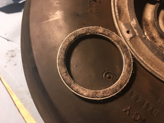
One of new felts
And, I put the wheel back together. And then... And then, I couldn't tighten it back right. I have to align the hole in the axle nut for the cotter pin... I could either get it under-tight (with perceptible play in the bearings - not good), or a bit over-tight (so that the wheel will spin, but with some measure of resistance). Remember, I said that my mistake number one was not checking how freely this wheel spun prior to pulling it off? Now, I was paying for it.
I tried flipping the bearings around (because I didn't note their original positions), thinking that maybe that will help. Nope. No change at all.
Oh well. I couldn't do anything about that at that point, so decided to settle on "a bit tighter" option.
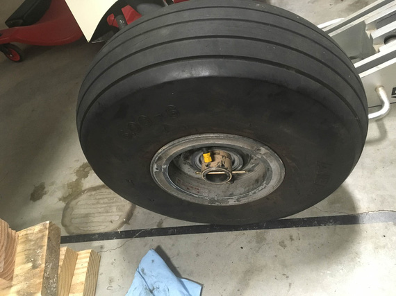
Cotter pin
With the other wheel, things went much smoother (the second time you do the job, it takes you 10% of time it took you to do it the first time, right? :) ). It came off, was cleaned, and got back on, with new felts and bearings in the original positions. Nut got tightened to super tight, loosened, and tightened to finger tight - and the wheel was perfect. No play, and no "drag".
Le double sigh.
So finally, it was the time to put things back together!
Putting the Brakes Back On
That was almost pleasant, after all the mess-aroundary with bearings. I cleaned up the pins' glide bushings, and lubed them with Dri-Slide (graphite + moly) lube Parker recommends.
And then... Calipers on, slide the bolts in, torque.
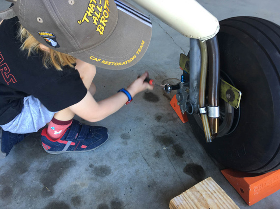
Putting calipers back on
Even a child could do it! By the way, that's the left wheel - remember I was mentioning the breather hoses routed to that wheel? There they are, in their awesome oil-spraying glory...
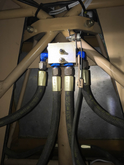
Parking brake back on
Put the parking brake back on.
Phew. Now, finally, we can bleed and test!
Bleeding
Now, there are two approaches to bleeding brakes - either bottom up (push fluid up thru the bleeder valves), or top down (sit in the plane and squeeze the pedals while the other guy opens and closes the bleeder). Bottom up is inherently simpler.
Some time ago, my buddy Dick was showing off his fancy bleeder he got from ATS.
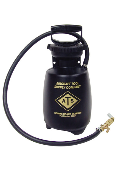
ATS Brake bleeder
Hmmm.. What is that reminding me of? Aha! Bug sprayer! That's right
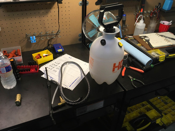
Bug sprayer
Now, a few minor modifications, and...
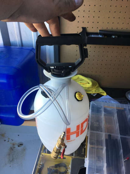
DIY brake bleeder
Pump it with air, open the valve, and the brake fluid gets pushed out thru the line that attaches to the bleeder valve on the caliper. Child's play.
For bleeding, I dragged my good friend Nick S. to give me a helping hand. I could've done this by myself, but having someone watching over the "other end" (it either being the end that pushes the fluid in, or the end out of which the fluid comes out) makes the job much more pleasant.
Now, the way brakes are plumbed on the Charger is, each side goes from it's caliper up the gear leg to the parking brake valve, then to the Master Cylinder, and from there both Master Cylinders are plumbed into a tee, from which the single line (the one I was re-making earlier) goes to the reservoir on the firewall.
We decided to bleed each side up to the tee first - to minimize the amount of air ending in the "common" line between the tee and the firewall. After bleeding each side up to the tee, we'd attach the "common" line and bleed each side up to the reservoir, letting at least a cup of fluid to flow thru, ensuring that we push all the air out.
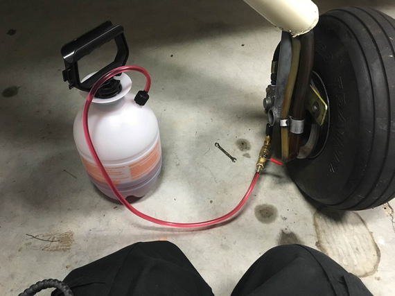
The setup
The plan went without a hitch, aside from the fact that I initially forgot to open the parking brake, and was trying to figure out why the hell the fluid won't flow. Hehe. Nick called it, too!
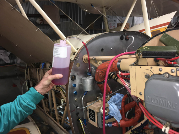
Nick holding the fluid line from reservoir
Finally, the moment of truth. The brakes were firm and nice, held well, and no leaks nowhere! Now, I need to double-check this - next time I'm in the hangar for a good few hours, I'll set the parking brake to keep the pressure in lines, and see what happens - but initially, everything held just fine! Phew.
So finally, the last bit was left.
Finishing the New Line Install
Now, the new line was finally in place, and all that was left was to install some ADELs to hold it.
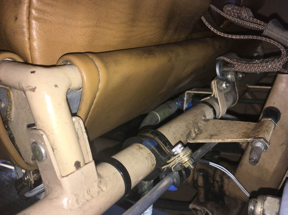
ADEL One
That one took ... an hour! Very nasty spot and hard to get to. I had to find a better way...
Now, there are fancy mods to ViceGrips (or you can buy them for sizeable chunks of cash pre-made) to hold ADEL clamps together while you're inserting the screw and starting the nut. I don't have them.
Some people use safety wire.
I decided to try...
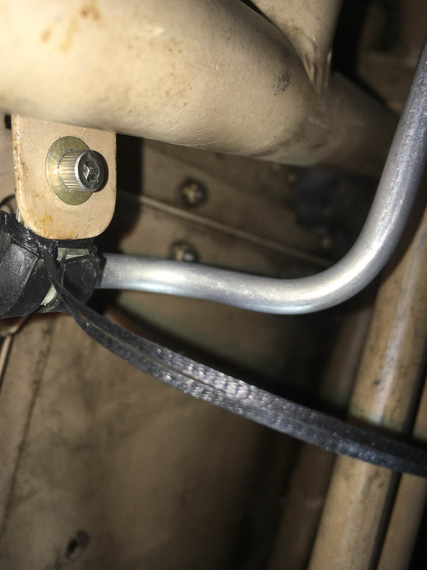
Lacing cord!
It works great, too! Just double up and "noose" it around - it holds a clamp like a charm in the "closed" position while you fiddle with the nut! Even Jack came out to see that.
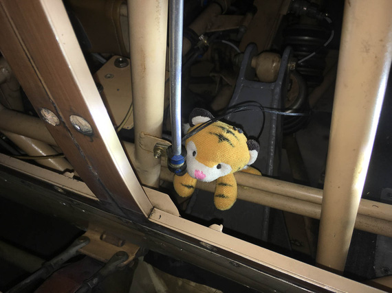
Jack inspecting the work
With those clamps installed, I had to tie a bundle of wires going across the tube to the front stick's PTT switch. That one was one hell of a contortion exercise, under the front seat's front edge and behind the stick, but I managed after a couple of tries.
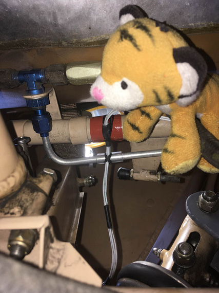
Lacing the wires to brake fluid line and structure
And finally, a couple more clamps along the length of the line on the fuse to hold it in place there. Some TorqSeal, and we're done!
I worked out a method to these, finally, I think. I use a long (~2 inches) AN3 bolt first to "thread" the clamps on, and then close them with a wrap of lacing cord using the "noose" method ("Method 2" here). I then remove the long bolt, install the final bolt, and start the nut. When the nut brings clamps almost to a close, I cut off the nooses, and tighten the nut. Works like a charm!
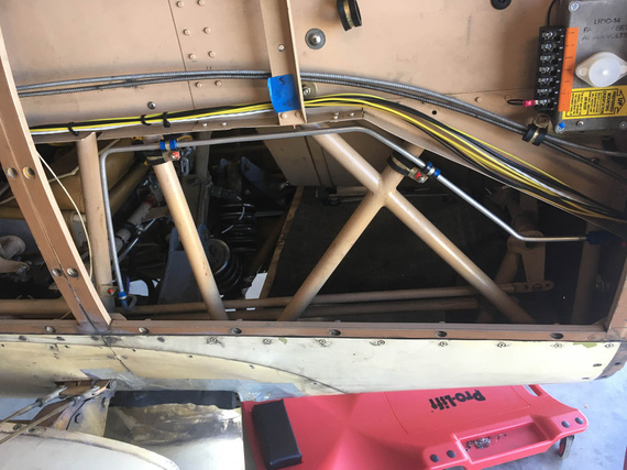
All done!
So, there. A pretty big job now complete - brake system rebuilt, re-bled, and ready to go.
PS: I was considering where to put this - under "2019 Annual" or "Electrical Rebuild" category... decided to pile it into the "Electrical Rebuild", because basically as a part of this rebuild I'm doing a bunch more stuff.. This is basically becoming a "minor restore" project... But still, the main theme is "Electrical Rebuild", and I'm keeping it under this section.
"you're gonna have to key the mike. I can't see you when you nod your head."
-ORD ATC
Up ↑
Bending Brake Lines
... and fitting in place
| On: | Sep 30, 2019 |
| In: | [Chickenhouse Charger] Electrical Rebuild |
| Time logged: | 12.5 |
| Tags: | 6781G, MA5 Charger, Annual, brakes, bending, tube |
So, yet again, last few weeks turned into working on lots of little bits simultaneously.
But, finally, one of them is done - and therefore, something to log.. ahem, pardon, b-log, about :).
The brake line.
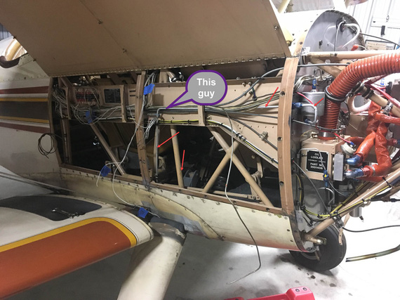
The old brake line
I needed to relocate this bad boy to free up room for the Voltage Regulator. This is the older picture - I have long bent it out of the way and cut off a chunk. It was to be relocated to run below the conduit.
Well, first, we had to locate the hole in the firewall. And that depended on the line to the reservoir, firewall forward.
After having thunk a bit about it, decided to replace the 90 degree fitting in the reservoir with the 45 degree; and the firewall bulkhead fitting with a 90 degree. That'd minimize the amount of bends and make for a neat job.
So, firewall forward we go first - that will locate the bulkhead fitting and the hole.
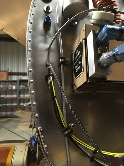
Mockup one
This is with old fittings in the firewall and the reservoir. The clamp on the mockup line is using an existing hole in the firewall - nice happenstance; I'd have to plug it with a "blank" bolt otherwise.
Then, "project" the tube onto the firewall, roughly mark the center, and drill!
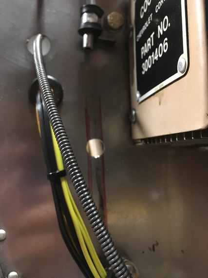
New hole!
And now, to the most fun part. Making the tube.
This was another first - never done tubes and flares before, so first of, had to figure out how to flare them properly.
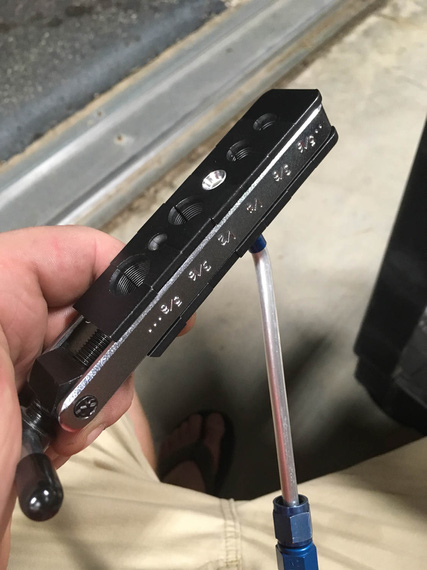
Flaring tool
Question: by how far does the tube have to stick out of it to arrive at the correct size flare?
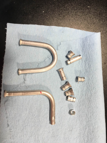
Practice (evidence)
Answer: 0.035. For the -4 tube. :) Yeah, those practice flares are not ALL the ones I made. Just some of them.
OKay, so the next question was how to actually make it fit.
My first thought was,
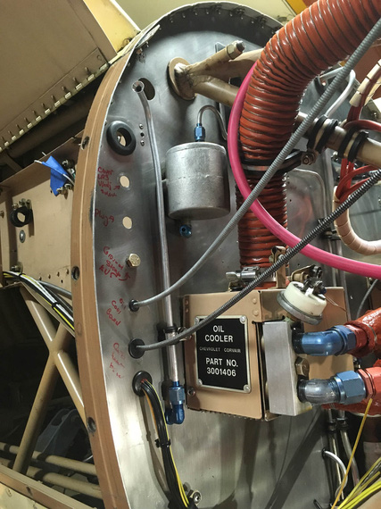
Bottom hooked up, top not bent yet
- Hook up the long portion (bottom)
- Mark out the centerline of where the bend should be
- Bend
The tubing bender has alignments marks for where the marked CL should go for different angles of bends.
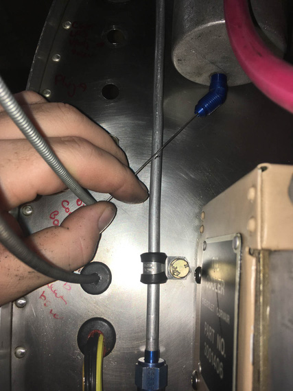
Marking centerline
What I didn't realize is that on this short a run, even a little error (bend being off of the ideal centerline by as little as 1/16") would cause a total misalignment.
It did, of course.
Okay, second try.
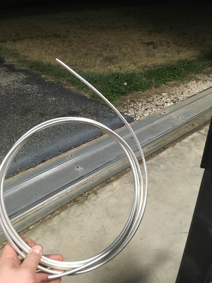
Real material!
I pulled out the roll of the new tubing, too. Partly to motivate me. Partly because I ran out of the chunk I've cut off of the old line.
This time, the idea was to bend it first and get the bend angle just right. Then, trim to correct length.
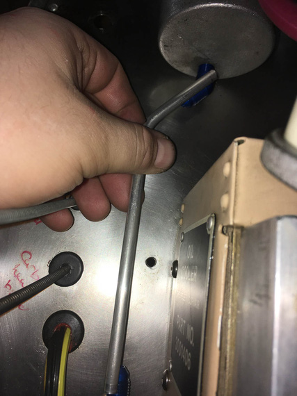
Bend angle first
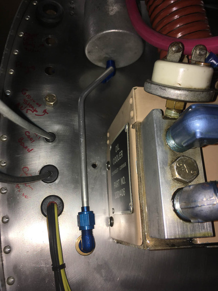
Trim, flare, hook up the bottom and mark the top
This actually worked.
Question. If you have a fitting with a flared end, where to place the cut mark, so that after you cut, and deburr, and flare it, while it's sticking out of the flaring tool (un)-precisely 0.035", it fits?
Answer? I don't know. I think I got lucky :)
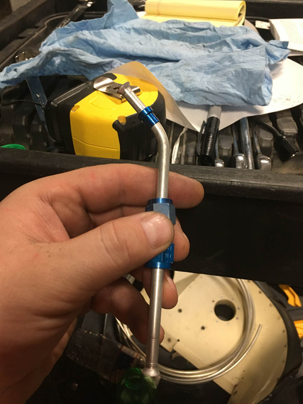
All done
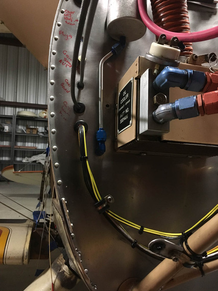
Installed
It fits perfect. I have no idea why the fitting there looks crooked - probably weird camera angle. It's straight :).
Okay. Time for the Big Kahuna - the actual long line, running along the conduit, and under passenger's seat.
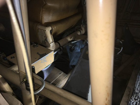
Under the seat it goes..
See that line? It goes down, turns, turns again, and again, and then goes to the center of front seat's front, and goes under.
It was rubbing against structure in a spot, too - so I wanted to clean all that up.
~30 minutes of head scratching yielded clamping arrangement that would work.
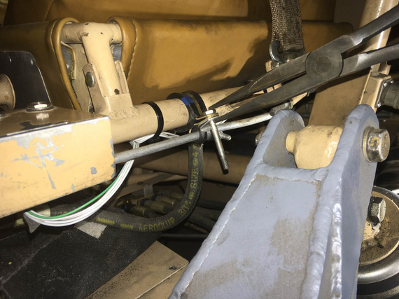
Clamps
By the way, I am stealing this arrangement shamelessly from my friend Mr. Gary Vogt of AuCountry Aviation fame. He uses similar arrangement to organize wires along motor mounts. Genius, really - and I have never seen this before (but I likely am a total idiot, anyway).
One final mock-up, and we're good to go.
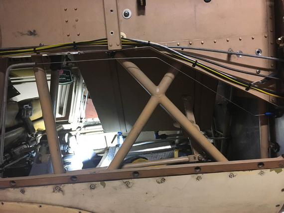
Safety wire for mockup
BTW. How do you make safety wire straight? Chuck it into a drill, and spin a bit :). It'll work harden a touch, and straighten out.
Okay, now, let's do the actual new line.
Unbend a long enough piece of tubing from the roll. Pull out the old line. (and use it as a template!)
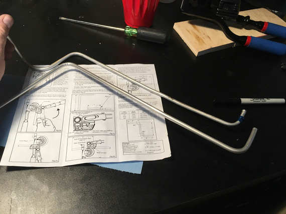
First two bends
Old line on the top, new on the bottom. I made the "tip" (that first section on the left) longer and planned to flare it later - can you guess, will that bite me or not? ;)
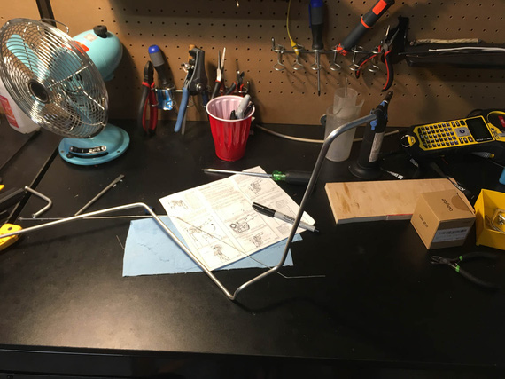
Getting close
Once I got to the point where the complex section (the one that goes from under the seat, to the side of the plane, and then up, and down again to run parallel to the conduit), it was time to try it on.
Maneuver it in.. it fits! Perfect! Bends clear all the right spots and fit in all the tight places.
Okay, now, time to actually attach it to the fitting under the passenger seat, hook it up with temp clamps, and do final bends and trim to final length in place.
But first, I need to flare that end - the one to go under the seat, where I left somewhat a longer stub to be trimmed later.
I trim it. Perfect length.
Crap! It does not go into my flaring tool now. It's way too short for it. WAAAY too short.
See, the flaring tool has some thickness to it. The sleeve has to fit on the tubing before you flare, and takes up another 1/4" of it's length. And, it won't go thru the bend. So there's a certain minimum length of straight tubing required for you to be able to flare it.
And, I already cut it off :( And I can't unbend it - it'll just break.
Okay, I'll admit to this. I did try to unbend it. I annealed it back to soft (torch + sharpie as temp indicator) and actually did succeed at it. But, bend flattens the tube some - and the sleeve still won't go over it.
Besides, bending this big Kahuna was actually not that hard - much easier than I thought, with old line acting as template. And, I had enough tubing. So, I decided to re-bend a new one.
Second try, I flared first. And then, I realized that Remo has probably bent his with a different kind of bender, or had a different kind of flaring tool - my bender would make that first section a bit longer than what the original line had.
Well... it wouldn't interfere with anything (I checked). It'll make it run a bit at an angle, and stick out from the seat a bit more... a bit uglier, but not a big deal (and I'll try to massage it into a bit more parallel run during final install).
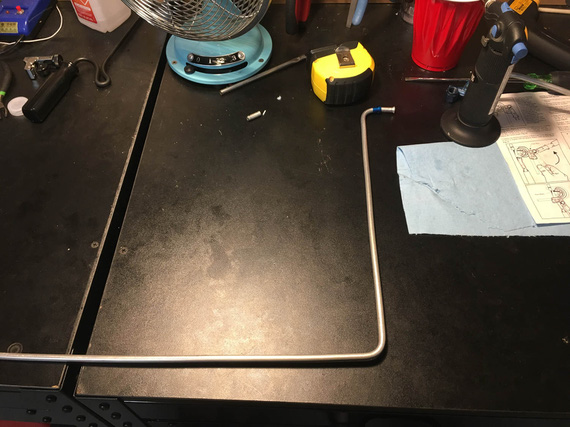
First bends - the first section (with sleeve and flare) is longer than original
Oh well.
Finished bending it, and installed it into the plane.
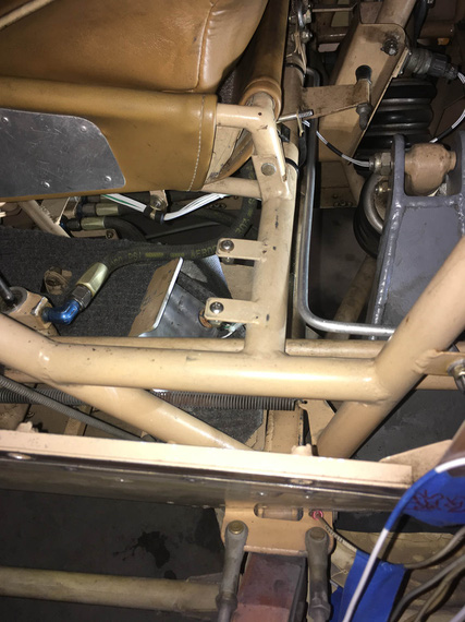
Seat to side...
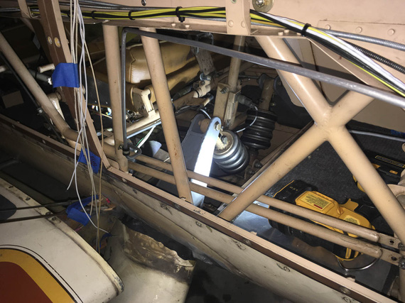
...and up the side
By the way, this is how this looks from under the plane.
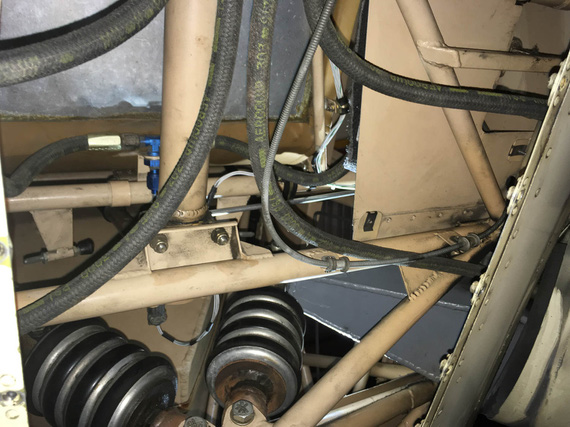
From under
The "front" of the plane is on the bottom of the pic. Can you find the line? (hint - it feeds the T with hoses attached to it. Hoses go to master cylinders under rudder pedals).
OKay, so now to final bends and trimming.
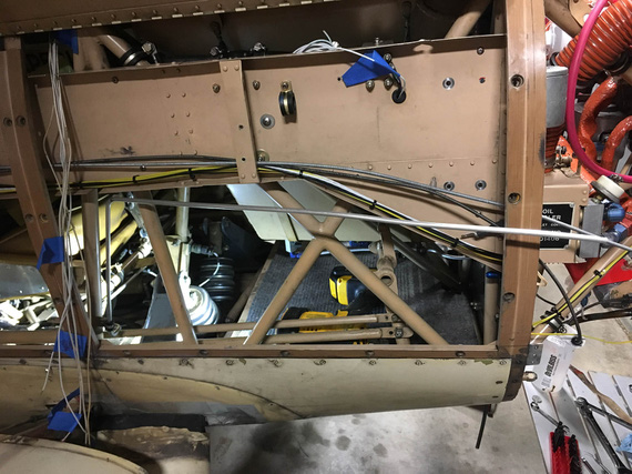
Still needs to be bent and trimmed
There'll need to be two more bends - "down" to follow the conduit and "out" to hook up to the bulkhead fitting on the firewall.
That geometry would need to ensure that I have enough straight tube to successfully flare it - learned my lesson there :).
So, our little safety wire mockup to the rescue.
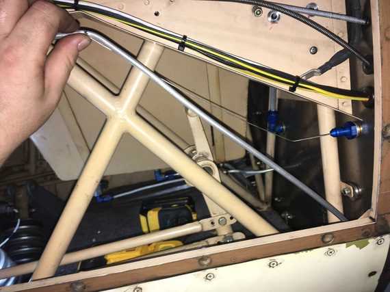
First bend made, marking / eyeballing the second
What I didn't realize is that this long line is much easier than a short stub. Even if you make a mistake, you can massage the line into compliance, "smudging" your mistake over the whole length - mistakes like wrong angle, a bit short here, etc.
Though, marking precisely does help. :)
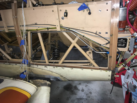
All done
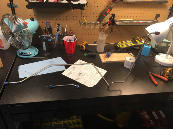
Two new tubes, all ready
I guess, mounting and bleeding is next; but for that, I need to replace the busted cylinder on the wheel, attempt to fix the leak in the parking brake, and re-pack the wheels (or I'll be re-bleeding the brakes later). I want to install the voltage regulator first, too, because that will minimize me messing with fasteners in the vicinity of this line.
Oh well.
PS: at the time of this writing, I am actually more than 50% thru with both of finishing up brakes, and voltage regulator. :).
"Approach, what's the tower?"
"That's a big tall building with glass all around it, but that's not important right now."
-ORD ATC
Up ↑
Race for the Engine
...or was it pickles?
| On: | May 17, 2019 |
| In: | [Chickenhouse Charger] 2019 Annual |
| Tags: | 6781G, MA5 Charger, Annual, engine, Rotec TBI, prop |
So after having discovered the electrical mess, I realized that she's gonna be sitting for a while.
Which meant...
Pickle time! Damn, this pickling thing is becoming a thing, excuse my tautologies...
I had to put her together enough to be able to run the engine to circulate and warm up pickling oil.
And she was apart. With intakes off, TBI almost off, no oil, and such.
Fuel / Intakes
So first, it was to be intakes.
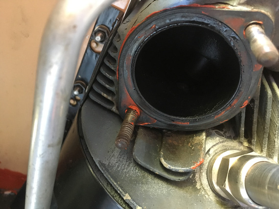
RTV where there should be none
Somebody put RTV to "seal" the intake gasket. Oh well.
Did you know that those 1 1/2 inch rubber hoses that go on intake tubes are much easier with very thin coat of oil?
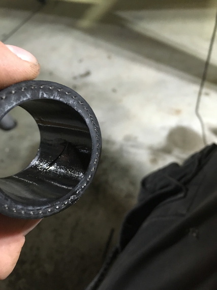
Oiling the hoses
And then, it was the TBI.
Recall that when I was putting her apart, I found pipe dope on the TBI inlet port?
Let me explain.
Fuel goes into gascolator. Then it branches: one branch goes to the engine driven pump, the other goes to the electric pump. Then, they go to the regulator on the TBI. Then, a couple of 90 degree fittings feed it into the TBI's inlet port, which has the "last chance" screen in it.
That's the port here, right above the airflow straightener:
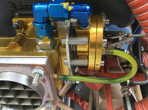
TBI from the down low
See that white gunk? That's Teflon dope. "Aircraft grade"; whatever.
Here's the problem.
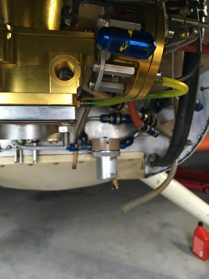
TBI inlet hole
Fuel has to go there, into that inlet hole. That's what the screen fitting screws into. Right past that, inside the TBI itself, there's a turn, another turn, and a spray bar that sprays gas into the intake, injection-style, thru a tube with a bunch of tiny holes. That's why there are screens in the fuel system: to prevent gunk from clogging up those tiny holes.
So now, what happens when you take a male fitting out of a female threaded hole, and the fitting was doped? Some of that stuff ends up on the female portion. Next time the fitting is put in, dope remnants will be pushed in past the engaged threads, and possibly clog up the works.
Not. Good. At. All.
That's why there is the copper crush gasket behind that screen fitting - to seal it to the TBI body w/o requiring anything extra. You can kinda see that gasket all smudged around with that dope on the first picture.
So I had to deal with it.. Clean it out somehow.
It was crumbly, but sticky enough to not want to come out.
I tried every solvent on hand. Nope.
I tried carefully scraping it out with a dental probe. Yeah, kinda worked, but I wasn't satisfied.
I tried every solvent in my buddy Dick's hangar. Nope.
In desperation, I drove to the local Home.. strike that, Aerospace, Depot, thinking about picking up every kind of solvent they had and I didn't.
And then, I remembered this:
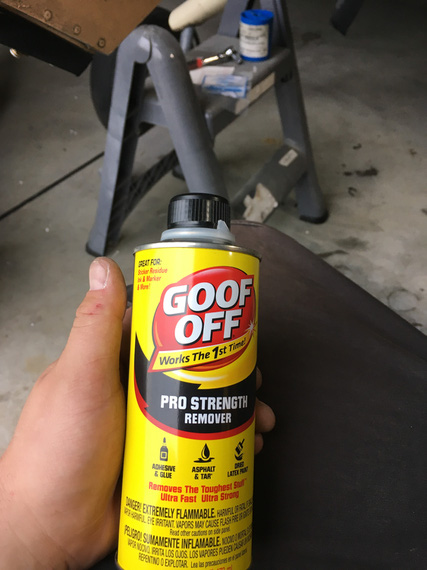
Goof-OFF!
I don't know what kind of concoction that is; but it worked! The hole was clean. Next time was a couple days after, and when I got back to the hangar, I discovered that it has turned into a lake :(
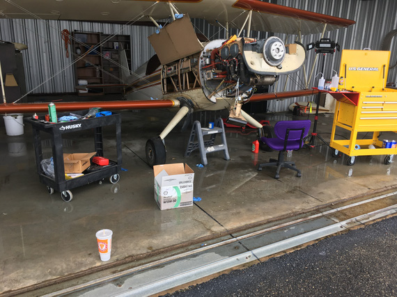
Lake in my hangar
Grading's all screwed up around our hangars, and when we get lots and lots of rain, they flood. Not too much though, luckily. This was the second time in the past few weeks - first time, I had my tools scattered around the floor. This time, I was smarter...
Anyway, back to the TBI. The rest of it went together quite nicely. I discovered that there was TorqueSeal put on the idle mixture screw.
Why? No idea. That screw is spring loaded. Should stay put.
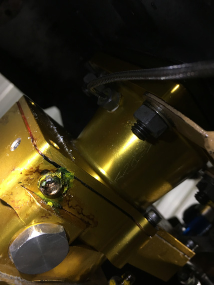
Torque Seal where there should be none
I wanted to flush the lines and then the TBI to make absolutely sure none of that dope went it. The best way to do that would be with the electrical pump; but I'm a one man show.... and the switch for it is 5 feet away from the firewall.
So, I had to rig me up a little doodad.
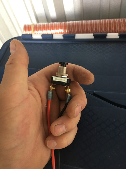
The simple click switch
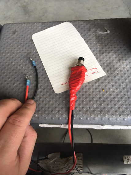
.. with ring terminals
The ring terminals were hooked up to the Master Solenoid in such a way that when the button was clicked on, the Solenoid would close.
The pump was turned on.
This way, I could click my button, Master Solenoid would close, and the pump would start running. Neat-o! I'll need it later, too.
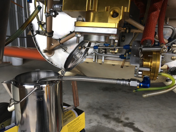
Flushing - braided hose provides nice bond to the airframe
The Pickling
I borescoped the engine (looked alright - I'll post a report about this later, maybe...); and it was time to fill'er up with oil.
Pickling oil was mixed up next, and into the engine it went.
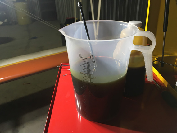
A pitcher of pickling oil
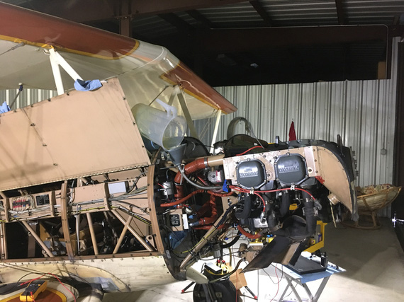
A recipe for a mess...
After filling the sump up, it was time to check for oil pressure. Lycoming tells you in SB1241C to pre-oil your engine by cranking with the starter in 10-30 second bursts until oil pressure comes up to 20 PSI.
Well, oil pressure gauge on the Charger is finicky, so I wanted it to at least move.
Oh wait. She has an ignition/start switch. No way I can use that to crank and not have a hot mag w/o messing with P-Leads.
Crap.
Also, I might want to crank from around the firewall (the prop was still off).
But I had my pushbutton doodad!
So I rigged it up to the starter solenoid this time.
Of course I misunderstood the way the starter solenoid was wired.
It had two terminals.
I thought one of them was ground; with the wire going to the firewall. The other then was supposed to be positive.
That didn't work.
I measured it - between those terminals - nothing. "Dead starter solenoid", I though. Crap! It was 8pm. Auto parts stores were closing soon.
I rushed to a nearby O'Reilly. Picked up a starter solenoid. Went back.
Measured it too. NOTHING? How come? Something was amiss.
Only then I started suspecting that something was off. That other terminal on the original starter solenoid I was hooking my positive wire to was all corroded and looked like it never had a nut.
OH! The way it's supposed to be wired is that positive goes to the same terminal where that wire I thought to have been ground was. It wasn't a ground wire - it was a diode. And the ground was off of the case of the solenoid.
Okay.
So, we're cranking now.
30 seconds. No pressure. 30 more. No pressure. Crap!
I unhooked the oil pressure sending hose (the one that hooks up to the line that goes to the gauge).
Crank. No oil. A couple bubbles is all I got.
CRAP!
The oil pump de-primed itself?
Kinda makes sense I guess? The plane was sitting for way too long :(
So, I took off the oil cooler return line. Dumped another quart of oil in there.
I had this hose fitting that goes on top of an oil bottle that was very neatly set up to mate with the engine oil hose's flare: so I could squeeze the bottle and push the oil in.
After the whole quart, I re-hooked the line back onto the oil cooler, and tried again.
Success! Now, I saw oil coming out of the oil pressure sending hose.
Hooked it up to the gauge line, and saw the gauge move, finally. Good.
Damn, with all that cranking I ran out my old battery I had put in there.
Now, have to flip the battery (to put in the good one - the flying one - I always use my old battery from the Cheetah when I mess with electrical, not to abuse the actual "production" battery).
Now, the top spark plugs go back in, the ignition wires get hooked up.
Prop time!
Bolt one - start it in. Bolt two. Bolt three.
Bolt 4. Doesn't go in? Not even a chance? What the hell?
I pulled the prop back off and laid it down. Put the front crush plate on top (that one positions the bolts).
No matter what I did, there'd be at least 3 out of 6 bolts that won't go in. This time, it was a few dry days, and I guess the prop moved enough to have the "top" and "bottom" holes (if looking at the prop horizontally) move closer together. It was off by almost a 1/16th.
So here I was. With an engine that was cranked for a total of a few minutes, and probably had scraped a lot of oil off of cam lobes and lifters.
With a prop.
I couldn't put on.
Which I needed.
To fire the damn thing up.
It was late. I tidied up, and went home.
The Prop
I wrote a note to Frank Johnson who made the prop that same night, and called him the next day.
He wasn't surprised. "Redrill" is a simple fix.
But I was a bit apprehensive, and this was a nice excuse to meet him. He's 2 hours away from me. We agreed to meet in a few days, at the first time he was available.
So, the engine with oil scraped off the lobes had to sit for another couple days.
Nothing I could do in that short a time...
Interlude
The weekend hit us; and it is a weekend in May, in Texas. Which means...
MUDBUGS!
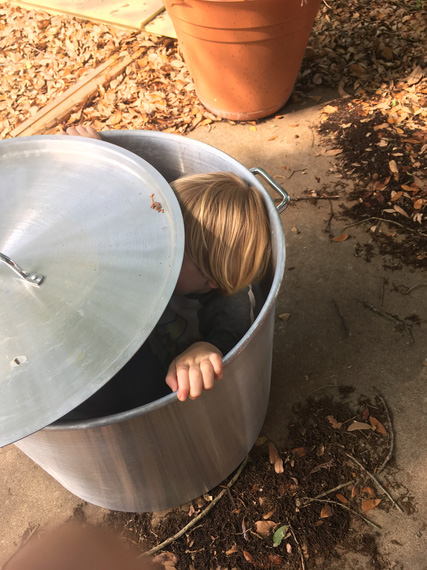
The annual fit inspection
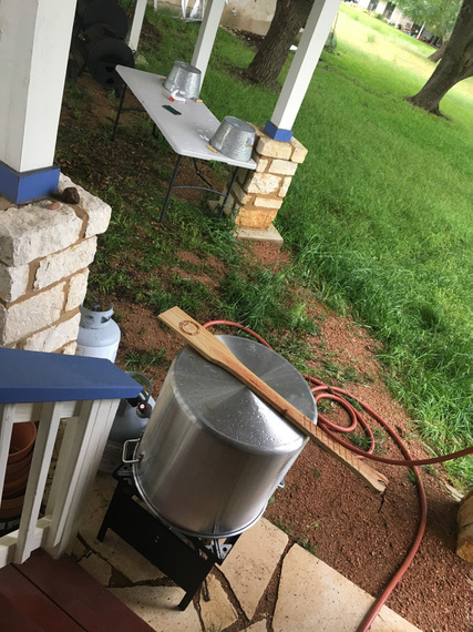
The setup

The fixings
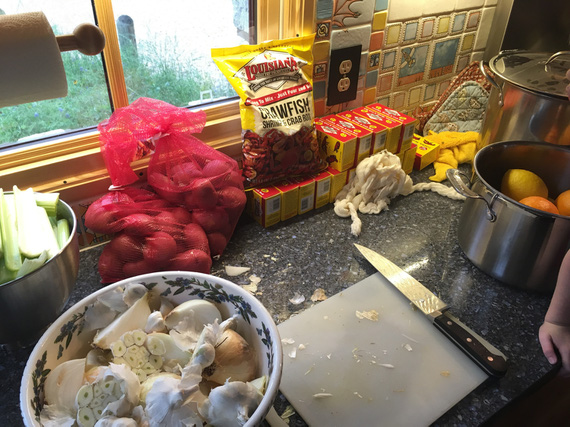
Prep
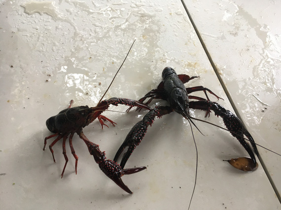
Aliens!

The Boil
The Finale
Into the trailer the prop went, and to Frank's we drove.
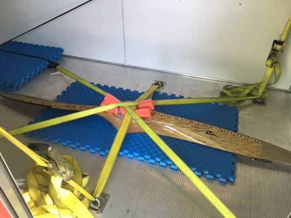
All tucked in
Of course, it took us 15 minutes out of 3 hours I spent there to fix it. The rest of it? Well, what can two guys who're crazy about airplanes do at one of those guys' shop and hangar? Hmm... What could we do? :)
The weather was swell, and I was in a good mood - and airport was on the way back from Frank's.
So, I went straight to the airport.
The prop went on beautifully.
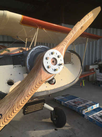
Finally, on
It was nice, sitting in a running, shivering airplane, to watch the sunset. If you looked up, it almost felt like flying. With the buzz, the shake, the smell and the noise.
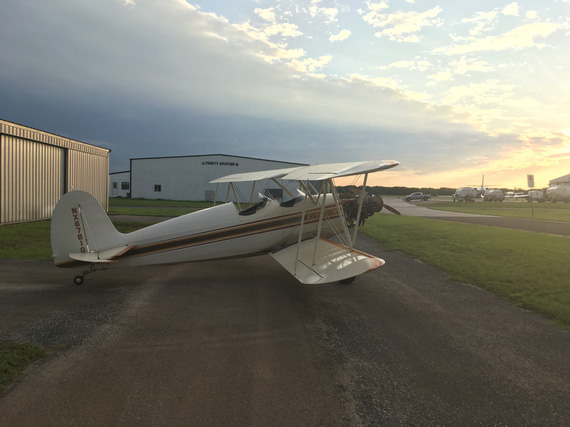
The Sunset
A couple days later, I went back to the hangar, sprayed the engine top and replaced spark plugs with desiccant.
Now, I can focus on the electrical mess...
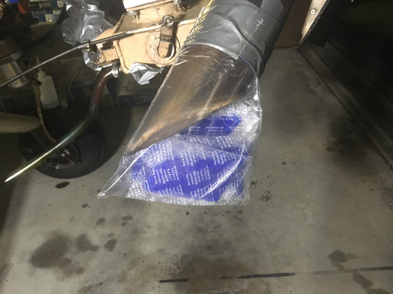
The Muffler plug
You can always depend on twin engine aircraft. When the first engine quits the second will surely fly you to the scene of an accident.
Up ↑
The Flying Fire Hazard
...sparks galore!
| On: | May 16, 2019 |
| In: | [Chickenhouse Charger] Electrical Rebuild |
| Tags: | 6781G, MA5 Charger, Annual, electrical |
This thing nagged me for a while. The Charger did not have the Field breaker. For that matter, it didn't have the Alternator master breaker, either.
It had this weird "main buss" breaker for 60 amps, but that didn't look like the Alternator breaker to me.
So in between dealing with other things after having decided to put her thru Annual in 2019 a bit early, I was running around with my multimeter, tracing wires.
Initially, I quickly discovered that some lines were definitely not fused; like Battery -> Main Buss line, and thought I'd put inline fuses into them, and be done.
She has an old charging system; a mechanical switching voltage regulator, and a Delco Remy alternator seemingly from a tractor:
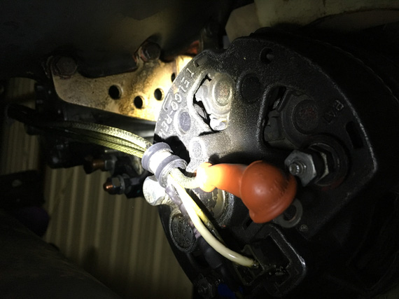
The old Delco-Remy
Voltage regulator didn't make sense. It had 4 wires (should be 2: supply and field output, or 3: supply, sense, and field output).
Alternator didn't make sense. Instead of 1 wire for Field input, it had two wires.
Additionally, Battery Contactor didn't make sense. One terminal had a wire going to it. The other was grounded....
Interlude
Battery Contactor is an interesting point here. Normally, one terminal is connected to the "always hot" side of it (basically, directly to the battery) and the other goes to the Master Switch. Master Switch turns the Battery Contactor on by grounding that wire, providing the negative side to the circuit. It's a safety thing. If that wire breaks, it'll either turn the electrical off (open circuit), or it will keep it turned on (short to ground). That's it.
But, one of the terminals on the Battery Contactor was grounded... that means, that the other terminal (the wire coming from the Master Switch) must provide positive side??? Huh? But where does it get it's power from?
Tracing
So to tracing we went. I spend maybe 10 hours trying to find diagrams and understand that alternator and voltage regulator hookups.
And me tracing it spelled my doom.
The Diagram
Now, I didn't trace the rest of it. Just the main distribution system. That was enough.
Shall we?
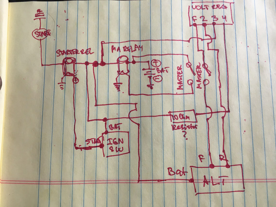
The current main power system of the Charger
Yep, the diagram is missing the main power buss. It's dangling off of the same spot where everything else that's interesting is - the Battery Contactor (marked MA RELAY) <-> Starter Contactor (marked STARTER REL) link.
So let's see what we have here.
- Lots of unfused wires. Do you see a single fuse here? Nope. That's because there aren't any. All the fuses are further downstream, off of the main buss.
- Voltage Regulator has this extra wire running to / from cockpit that isn't really necessary and could've been kept on the hot side of the firewall (terminal 4 wire)
- Alternator field broken at output (F->ALT) rather than at input (battery -> terminal 3)
- And the best part? Always hot wire that you can't turn off between the battery and the Master Switch to turn the Master Solenoid on.
That last bit bugged me. I couldn't find the damn thing. Even before actually tracing it, I knew that if the Master Solenoid is switched on the "hot" side, it needs to get the power from somewhere, and that only could be battery. But I didn't see any wires on the always hot side of the Master Solenoid. Only when I traced it, I actually traced the physical wire to where it goes, and then found it. It was so tucked behind the battery -> Master Solenoid wire that it was invisible:
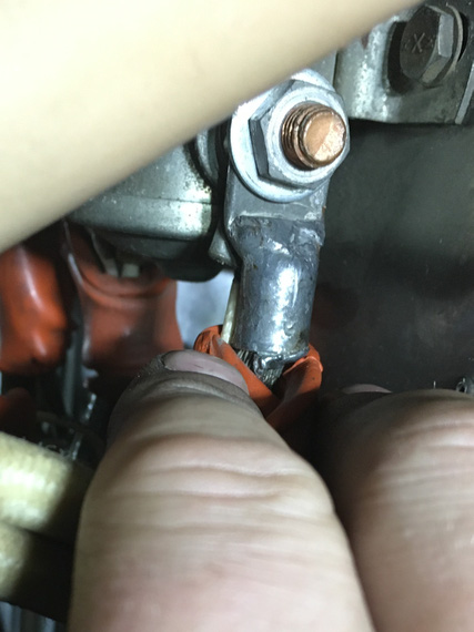
This little !@#!S@#....
Oh; and by the way, the Master Switch is the only switch that's soldered in, and w/o any good insulation around the terminals, and over-stripped wires. So that's just waiting to short, and the magic smoke that'll be let out behind the panel when that shorts can't be stopped (always hot wire, remember?)
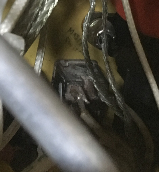
Master Switch
The Wires
So I kinda went backwards here; but I thought it'd be easier to see the diagram first.
Let's see.
Most of connections are made on this very nicely marked terminal block:
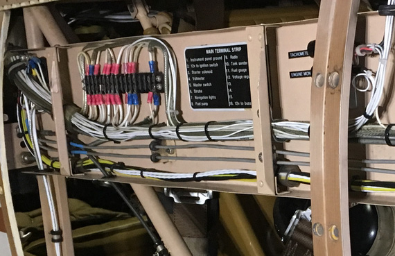
The terminal block
All the switched power comes out there, and every wire is marked. This actually helped a lot in tracing. This block is on the side of the plane, right next to the front hole's backrest.
You know what threw me off the most with that damned always hot wire (I ended up tracing it physically)? It's how it's hooked up.
Yep, it is hooked up to that terminal block. To the terminal... that is marked.. (drumroll).... "Master Switch".
Wait.. this actually makes sense... But where's the "return" from the switch?
Ah! It's the wire that's marked.... drumroll... "Fuel Gauge"!
So really, let's look at what's going on, shall we? Zoom in the image below, it's annotated.
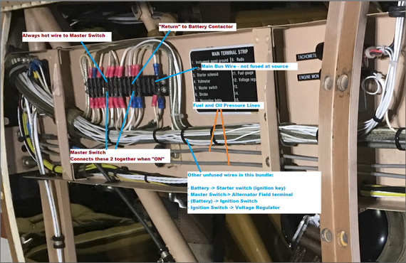
Untangled
So let's see. We've got this bundle of wires, a lot of which are not fused, and one of which is always hot.
The Main Buss wire is the thickest one (10 gauge maybe?) that's not fused between this buss bar and the source (engine compartment).
Oh, did I mention that this buss bar is on the side of the plane near the rear instrument panel (so that 10 gauge run, and the rest of the harness between firewall and the panel is about 30 inches long)?
What else do we see there? Oh! The two little 1/16inch thick aluminum lines carrying.. fuel pressure (and oil pressure).
Shall I say more?
Shall I say that there's a fuel tank in between the front hole (passenger) and the firewall?
That the wires run along between firewall and rear cockpit along that fuel pressure line (to fuel pressure gauge)?
That if one shorts to this very nearby fuel pressure line, it'll burn a hole straight thru it, and then ignite the gas that'll start coming out?
Yep.
Can I fix all of that?
Sure. But rewiring will be much much easier, because I have to touch pretty much everything. Re-running half of individual wires in a bundle is much harder than re-running them all.
So, I made a decision to rewire the plane... Sigh. Looks like I won't be flying for a looooong time.
Oh, and tell you what. Tracing wires on a biplane is dangerous. I ended up twisting my knee and pulling a muscle while trying to get behind the panel so badly that I couldn't walk (or sit) for 2.5 days :(.
Navy carrier pilots regards Air Force pilots:
“Flare to land, squat to pee.”
Up ↑
Annual 2019: The Cowling Conundrum
...Comanche, no Comanche?
| On: | May 15, 2019 |
| In: | [Chickenhouse Charger] 2019 Annual |
| Tags: | 6781G, MA5 Charger, Annual, baffles |
Baffle seals on this plane are original reinforced neoprene rubber, and they were in pretty beat up shape. There is a lot of gaps, they sag in places, making the seal really not that good.
So one of the things I decided to do is to redo them.
Pardon the cruddy pictures; but those ones are the only ones I have :(
The Nosebowl
One of the things I noticed immediately is that baffle seals were turned the wrong way in the nosebowl area; where the front "air ramp" joins the bottom of the nosebowl.
Here's the nosebowl and the front ramp:
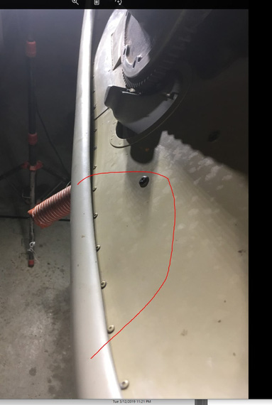
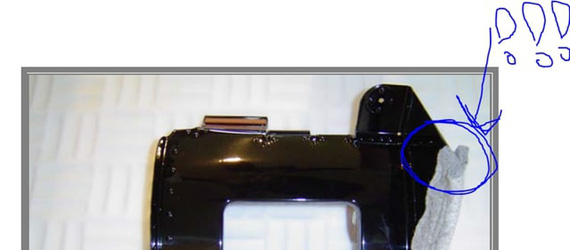
Front ramp
Notice the circled area? Here it is, from the back:
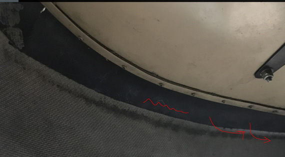
The behinds
That marked rubber seal is in the circled area. Notice it's turned the wrong way; "into" the cowling, rather than away from it? Ram air hitting that front "ramp" will "bend it in", and leak into the underside of the engine compartment - precisely where it's not supposed to go.
Naive me thought that it was just wrongly installed - the rubber needed to have been folded up and out, "into" the lip of the nosebowl.
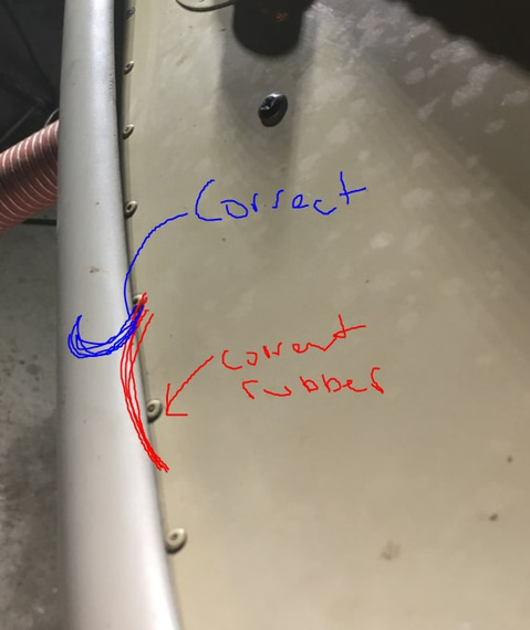
Correct and current seal orientation
Ha! Well, Remo (the guy who built the Charger) thought different.
There's just not enough room there. Everything is super tight. The seal just won't go there and stay there. There's just no room.
Look at the above two pictures - inside and outside - again. You'll understand why. Use pop rivet line as your reference.
Here's where the problem gets worse. Ramp is really thin - so with just a mild pressure, I can make that gap between the ramp and the bowl 1/4 - 3/8 inches. Guess what happens when ram air hits it... :)
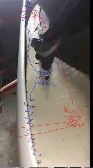
What ram air does...
Okay, so then I went digging.
I thought this was a standard bowl. I was right!
It's an old Comanche single style bowl (I think).
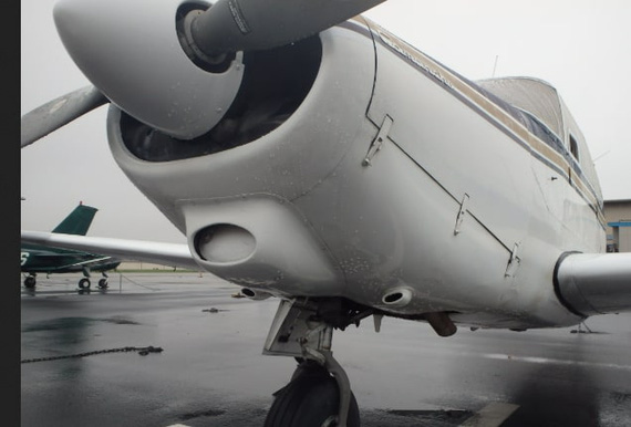
Comanche nose
Looks similar? I researched further.
Here's a guy making replacement ramps for Comanches, with some good pictures.
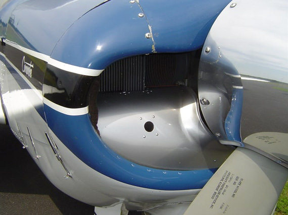
Front ramp on a Comanche
Okay; see the difference? Comanche ramps are curved the other way.
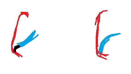
Changer vs. the Comanche
This is cross section. Mine's on the left, Comanche's on the right. Red is nosebowl; blue is this ramp, and black is my baffle seal.
Mine is "concave". Comanche is "convex". So if I got my thinking right, this makes the Comanche version more rigid facing the wind.
Drawing from the Comanche's parts' manual confirms this proper curve.
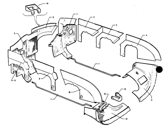
Comanche parts manual on baffles
The parts I'm talking about are numbers 11 and 12, bottom right corner.
But how the heck do they seal them? Notice that the material on the drawing above seemingly has some "dots" on it (as opposed to the rubber material on the side baffles).
Well, back to our "remade Comanche front baffles" guy.
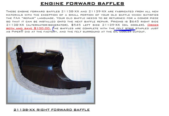
Forward baffles from Comanche Gear guy
Felt strip!
Well, I guess that makes sense. Felt wrapped around the front ramp.
Felt strip
Felt is thick and, contacting the nosebowl, I guess, will create a good enough seal if the ramp is rigid enough. I am guessing that Comanche's ramps are way more rigid than mine due to that opposed curve.
So where are we at with all this?
Remo probably built this noseramp himself. It looks very custom. It's too thin and doesn't have rigidity - ram air will flex bend it "into" the cowling. It's not sealed properly practically along all of that bottom edge between the bowl and the ramp.
The only hope for it is that it's aerodynamic-ish and looks like a "dozer blade" - curved up. Maybe the nosebowl lip deflects the air enough for it not to go under too much:
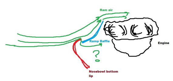
Airflow diagram
Can I replace the current rubber seal with felt?
Maybe. The front of the engine moves. The ramp's aluminum is very light - I am afraid that if I were to add any reasonable quantity of felt to it to hold the seal tight it will warp the aluminum via relative motion of that ramp (hooked up to the engine) rubbing on the bottom of the nosebowl. Or worse yet, make a hole in the bowl.
Can I replace the ramp? Well, everything's possible; but that's a massive undertaking. That ramp / nose baffle, Comanche-style, has that compound curve, and I don't have time or skill to do it fast. 2 months? Maybe, if I get lucky. BTW this is probably why Remo did it this way - because his is just an aluminum sheet, wrapped around the front of the engine, "neck cone" style, and cut to fit.
So, what do I do?
After discussing this at length with my good friend Ben, we settled on testing this out first to see how bad the air flow going "under" will be. I can mark the bottom of the nosebowl with some tinted oil, and go fly. Oil streaks will tell me if the air is flowing under a lot, or not so much.
I'll also replace all the other baffle seals, which will improve cooling. There's a lot of gaps to RTV, too.
I don't want to replace the bottom nosebowl ones, because actually there the rigidity of old neoprene rubber seals should help...
The three best things in life are a good landing, a good orgasm, and a good shit. A night carrier landing is one of the few opportunities to experience all three at the same time.
Up ↑
Annual 2019: The Rest of April
...and 1/2 of May
| On: | May 14, 2019 |
| In: | [Chickenhouse Charger] 2019 Annual |
| Tags: | 6781G, MA5 Charger, Annual, Rotec TBI, baffles, prop, fabric |
Well, as usual, I got too focused on the plane and the mess I got myself into; and didn't log things as they went...
I will split the notes in multiple posts; by theme / subject. Just general notes here.
Annual, Continued
We got together with John, my IA, and continued working on the plane early April.
We pulled the prop, so that I will have access to baffles (I wanted to redo them).
John re-riveted the air takeoff flange back to the front ramp.
Meanwhile, I started disassembling the fuel system to get to the screens, including the oil sump screen, and clean them.
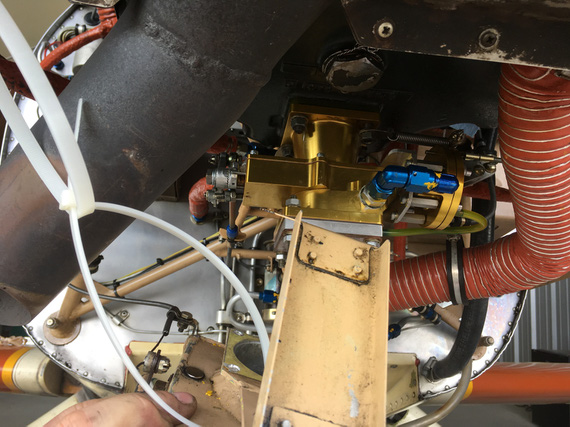
Airbox off
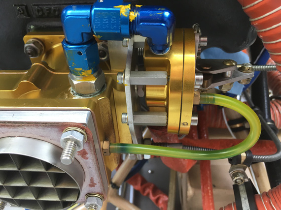
TBI intake airflow straightener
Okay, stop right there. See that fuel inlet, right above the air intake? See the little smudge of dope around the inlet fitting? Yep. Teflon dope. Rotec explicitly tells you not to put ANYTHING on there - there's a copper crush gasket behind that fitting.
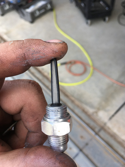
TBI screen
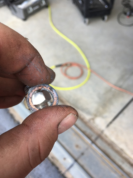
TBI crush gasket
See all that dope above? Okay, that thread on the TBI is a female thread. Dope will be all in it, and guess what will happen when I screw the fitting back in? Yep. It'll go into the TBI fuel galleys. Right to where that spray bar is with tiny little holes in it. Not Good (c).
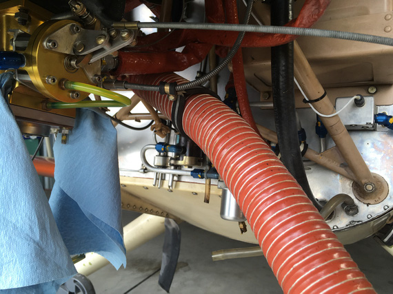
TBI holes plugged
Intakes
I noticed evidence of possible intake leaks, so without "burping" the engine, decided to pull the intakes and replace the gaskets. This is my karma. I did that on the Cheetah just a year ago, and scraping remnants of one of those gaskets and re-chasing the threads took me about 10 hours; maybe more.
Also: interesting note: she has intake tube clamps on studs and not bolts like every other Lycoming I've seen. Old, narrow-deck cylinders :).
Prop
When we pulled it, bolts were in the thru holes on the wooden prop really tight.
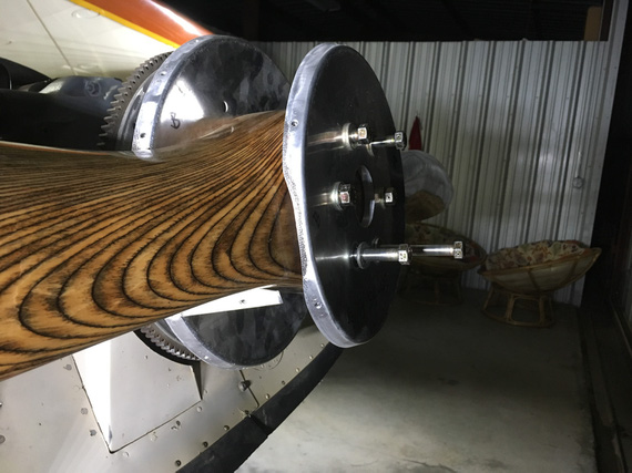
Pulling the prop
She has the prop made by Frank Johnson of Performance Propellers fame, and after contacting him, he just suggested to re-drill the holes and re-coat them inside with something.
Well, I got me a 29/64 (1/64 oversize) reamer, and went to town.
But first, I needed a rack.
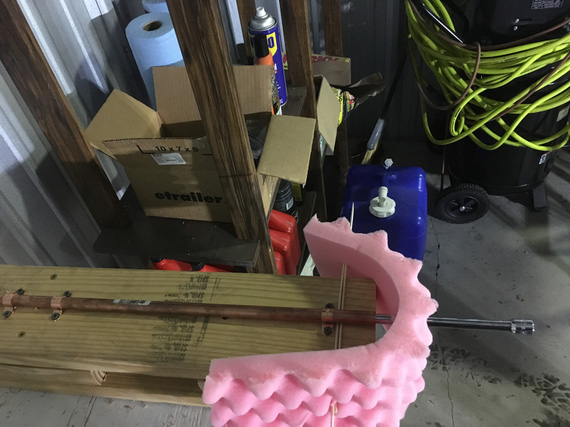
My prop rack
Built with a 1/2" pipe, some foam, pipe brackets, screws, 2x6s screwed to the table, and my 3/8" drive extension rod. You get the idea :). Redneck engineering galore.
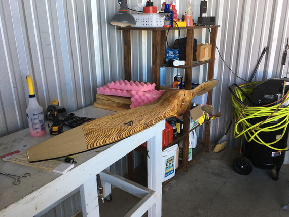
Prop on the rack
This whole thing was happening over a few days by the way; and when I finally got my reamer and had time to deal with it, the holes.. extended. Wood moves!
Hey, we had much rain then, and prop "swelled" a bit methinks.
But I still decided to fill the holes as much as I could.
Even got me some nice scales for mixing System Three ClearCoat.
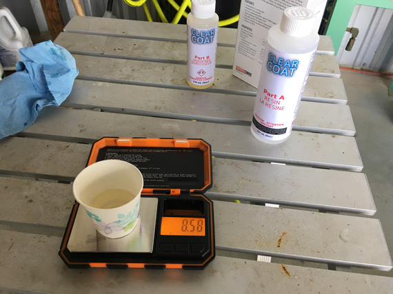
Mixing
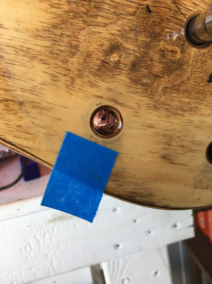
A filled hole
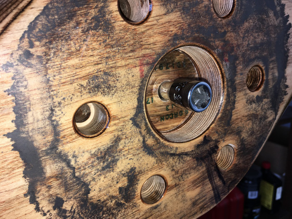
Backside
Fabric
Fabric on this plane is old. Flyable from what I am being told by experts, but old. Cracking, peeling paint.
Original logs say that she was covered in Polyfiber. But the current finish looks more like Imron and the company - "flexible" automotive poly. It's cracking and peeling around areas of high wear (prop wash, etc).
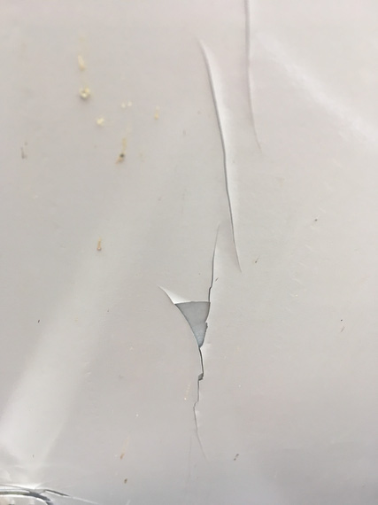
Sad fabric
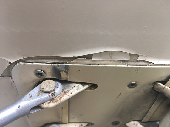
Sad, sad fabric
John (my IA) wanted to take a Maule fabric tester to it; but I didn't want holes in my wings.
I discussed this with a few guys that worked with fabric their whole lives, and we came to a consensus that for now this is fine. Will just fill with silver, and keep on flying. Incidentally, that's what Glenn has been doing, too.
Full Stop
I worked on baffles a bit, but then, everything went downhill. We'll talk about baffles in the next post. And the downhill part, afterwards :).
"Expect lower at the end of this transmission."
-ORD ATC
Up ↑
Annual 2019: April 6
...wing root fairings
| On: | Apr 06, 2019 |
| In: | [Chickenhouse Charger] 2019 Annual |
| Tags: | 6781G, MA5 Charger, Annual |
Only had a few hours today, so decided to concentrate on taking off the wing root fairings. As I mentioned before, the "back-side accessible" screws were set up to have nuts on them rather than nutplates. Well, I don't know about that accessibility....
It ended up being 3 hours for ~30 screws.
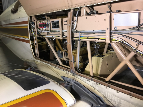
Root fairing off
Most of them on the back side of the wing require you reaching with a wrench thru the rear cockpit, and my arm is just barely long enough to do that successfully. Since nuts are nyloc, no way I can hold them with my fingers - they need a socket.
Some of those nuts are in a U-type channel over which the fabric is glued, and some of the holes are off-center: making it impossible to put a socket over them.
I could've ground a socket down; but I don't have a grinder - so especially one of the nuts took a while to get off. And oh, you have to do all that without dropping the nut and the washer onto the floor (and having them go into the tail). So the process looked like this:
- Get your hand in, try to put the socket over the nut.
- While holding the ratchet, try to put the screwdriver into the screw w/o missing it and poking a hole in the fabric.
- Undo the screw, almost.
- Remove the socket, take a strong magnet.
- Finish undoing the screw, hoping that the magnet will catch the washer and the nut.
Having magnetic sockets helped. They weren't deep enough to grab most of the fully tightened nuts because screws protruded from them. I used them as magnets sometimes, and sometimes used my magnetic "fishing for lost hardware" probe.
Now I'm writing this, I realized what I should've been doing is using a long extension and a 90 degree adapter on my socket. Damn! But this still doesn't solve the problem with some of the nuts that were hidden almost behind things that were in the way (ie, a trim control wheel's attachment structure that's welded into the fuselage).
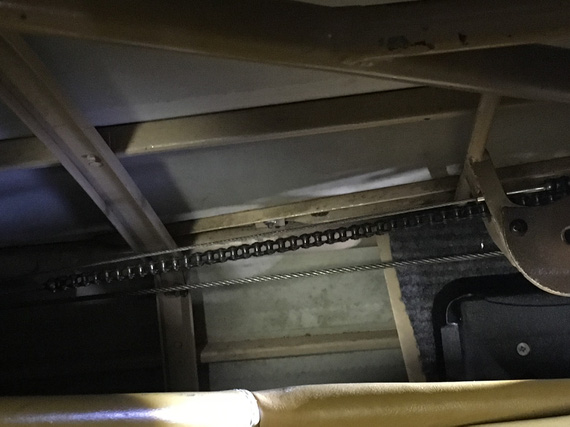
One of those pesky nuts
I'm considering replacing those nuts with Tinnerman-type and screws with sheet metal screws thru Tinnermans. I'd put some anti-chafe tape inside the U-channel, and then Tinnermans on top of it. Since Tinnermans are long, when undoing (or tightening) the screw, they will turn and touch the side of the U-channel, which will act as a wrench.
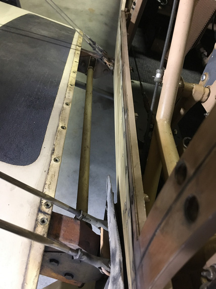
Wing attachment - right side
And that's literally all I got done today. Just took those damn screws out.
The similarity between air traffic controllers and pilots?
If a pilot screws up, the pilot dies.
If ATC screws up, the pilot dies.
Up ↑
Annual 2019: March 30
... getting familiar
| On: | Mar 30, 2019 |
| In: | [Chickenhouse Charger] 2019 Annual |
| Tags: | 6781G, MA5 Charger, Annual |
Decision
After getting the Charger, I have decided to fix a few basics.
- Clean plugs
- Change oil
- Give her a good look over
Getting a bit ahead of myself, a series of coincidences (airport closed, baffles' condition, intake leak, and others) made me decide to go thru the annu... sorry, Condition inspection (damn, will have to get used to new nomenclature :) ).
Notes
Cowling came off.
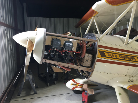
Cowling off
Discovered a few booboos:
- Cracked cowl inlet ramp: need to stop drill.
- Baffle seal behind the inlet ramp is turned the wrong way (Glenn was complaining about high temps - one of the reasons, hmm?).
- Top baffle seals are too hard and sag in few spots.
- One of the air take-offs off the ramp has almost un-riveted itself.
Since I will need some helps with skills and tools with riveting, and we'll need to pull the prop to change (and turn the right way) the seals, decided that I will put her thru annual.
Studying the systems (I was mainly concentrated on fuel and other al lines and hoses to see where things go), discovered a few things, too
- She has the Rotec TBI-40-MKI TBI installed, which requires a 40 mesh filter upstream of it. The only filter besides finger strainers in tanks is gascolator, which goes down to 72 micron (0.003) only. Need to get a hold of Rotec people and discuss this situation.
- The "low" end of the tank (in 3-point attitude) has a very nice drain fitting + drain cock draining behind the cowl. I am seriously considering adding a quick drain there - that is the lowest point of the tank in 3-point. My thinking is: water collected in the tank, goes to that lowest point; but there's not enough of it to go thru the take-off (which is in the middle). Then, when I raise the tail, it slushes forward, goes into the take-off, and reaches the engine right when I am just off the runway. Not Good.
- Some un-critical drain hoses are clear vinyl and hard as a rock. For now will replace them with clear polyurethane, and if that hardens, with rubber.
- TBI needs positive stops on the throttle quadrant. Need to check if they're present and adjust as necessary.
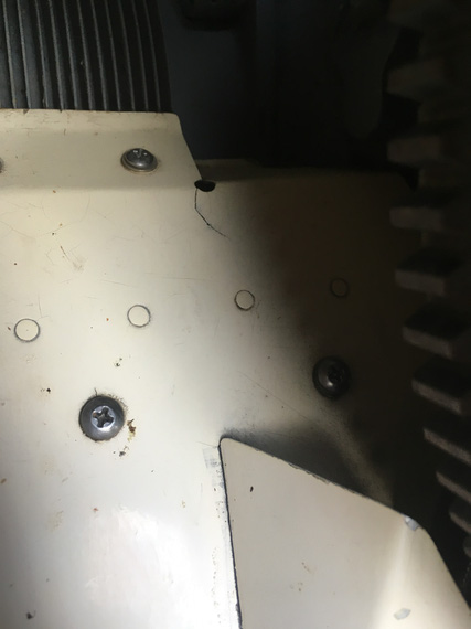
Crack in inlet ramp: stop drill
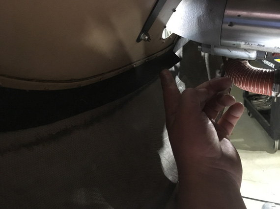
Inlet ramp baffle: turned the wrong way
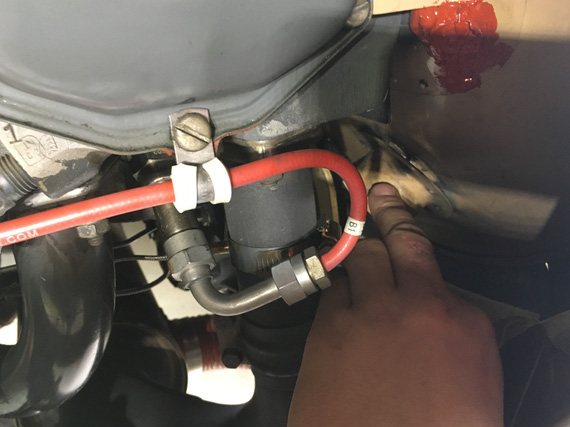
Inlet ramp's take-off flange - un-riveted itself
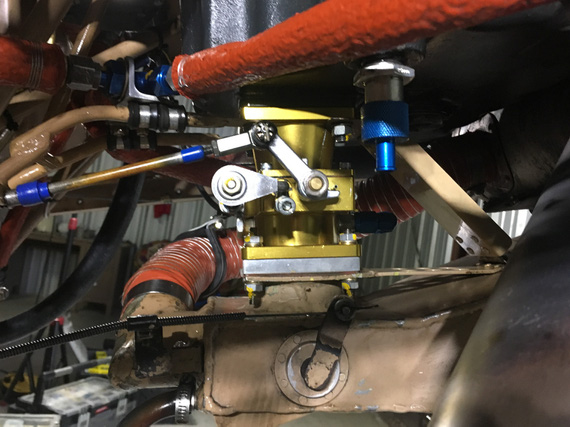
TBI
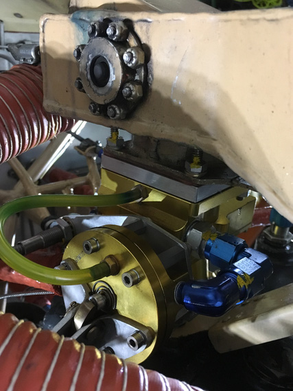
TBI - Regulator Side
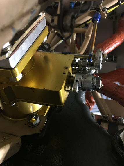
TBI - Throttle linkage
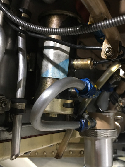
Electrical fuel pump and gascolator
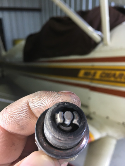
#1 bottom plug - in pretty good shape
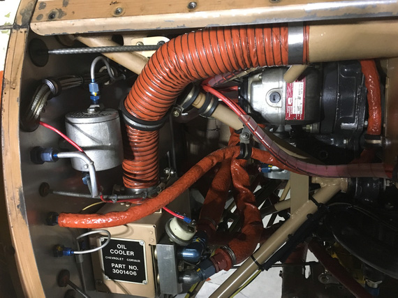
Engine compartment right side
Fairings
Spent the rest of the day taking off fairings and access panels. This is the first thing I thing could've been done better here methinks. Everywhere where it was deemed that the back side would be "accessible", Remo used #6-32 nyloc AN nuts on machine screws instead of nutplates. Well, some of those nuts are not accessible, and I gave up on quite a bit of them around the rear wing root fairings.
Need to standardize on fasteners' length so that I don't juggle 10 different screw sizes.
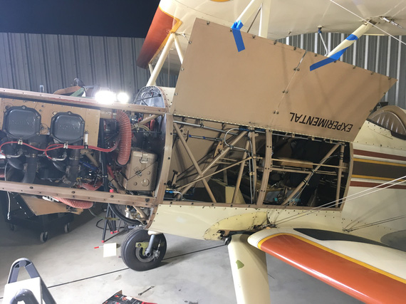
Gotta love that easy access!
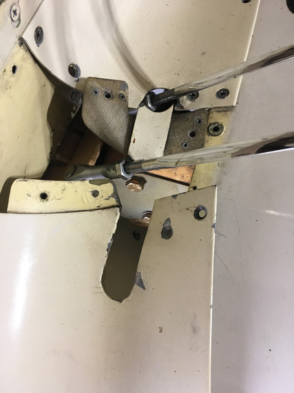
Flying wires' fairing
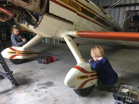
My laborers for the day working on wheelpants
Gravity, it's not just a good idea, it's the law.
© Copyright "79FT". All rights reserved. Feel free to cite, but link back to the pages cited.
This website only shows how I did things in my various projects. These pages are for information and personal entertainment only and not to be construed as the only way, or even the perceived correct way of doing things. You are responsible for your own safety and techniques.
