[79FT]: Building Things |
 |
Brakes and Wheels
fixin' and bleedin'
| On: | Nov 04, 2019 |
| In: | [Chickenhouse Charger] Electrical Rebuild |
| Time logged: | 23.1 |
| Tags: | 6781G, MA5 Charger, Annual, brakes, wheels |
So this one turned into a month long project, give or take. Sure, sure, I was doing other things, too: last one of which was completed October 9th... after which I was finishing this one exclusively, pretty much.
Damn. One month to finish putting the brakes together. Granted, I had a hiatus for a week and a half, dealing with fixing up bad (non-aircraft) plumbing and cutting (non-aircraft-grade) trees.
Regardless... Shall we?
...
After having finished making the new brake line, I naturally wanted to install it and call brakes done.
Some of the disassembly work documented here actually happened prior to the new line being bent up, but hey. Putting it all in one place makes for a better narrative in one context.
First, the Calipers
... one of which was cracked due to someone having overtightened the bleeder adapter. Oh well.
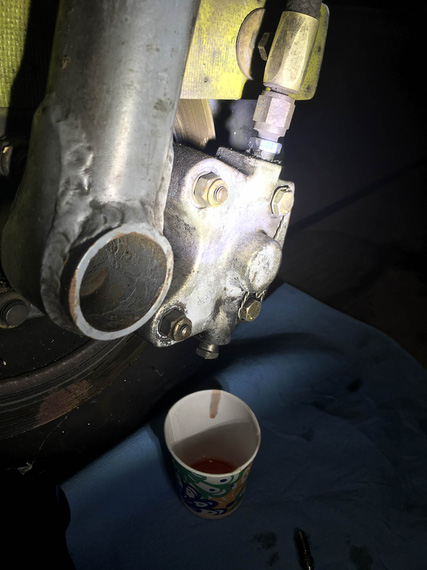
Drain
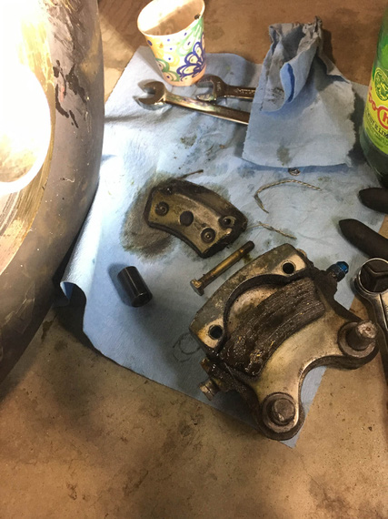
... and pull
Brake pads were soaked in brake fluid. For that matter, the disk was covered in brake fluid that hardened to molasses-like consistency (which mineral milspec fluid does, apparently).
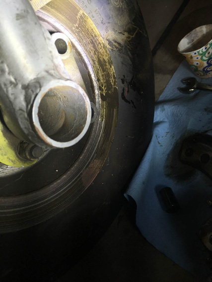
Ugly smudge
Intermission. By the way, it seems that this smudge didn't come from the dripping bleeder, but rather, judging by how the pads were soaked, from under the brake piston. Probably the o-ring was bust, and it was weeping from between the caliper and the piston. It seems that it had been a feature of the plane for a while.
Jumping a bit ahead of myself, on the other side, I discovered the brake disk somewhat dirty with oil - crankcase breather hoses are routed into the _left_ side wheelpant and terminate near the disk - clearly, spraying a bit of oil on and around it. You'll see those hoses on the pics of the left wheel below.
I think Remo's idea was to prevent oil on the belly from the breather. My friend's Ben contention was, this was a brake lock-up prevention measure; and when he brought it up, I immediately realized... leaking piston on the _right_ caliper was a lock-up prevention measure as well - to make sure both brakes are equally slippery - right one with brake fluid, left one with motor oil... At any rate,..
I will admit, this was my first caliper job ever, and anchor pins presented a bit of a problem. They're press fit in the caliper, and I didn't have an arbor press. Well, I used an old 1/4 nut that I banged on (gently!), and finished with a drift punch....
Tappy-tap-tap!
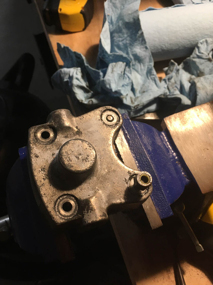
Tapping out the pins (aka anchor bolts)
With the caliper put apart, I tossed the old body, and took maroon scotch-brite to the rest of the pieces to clean them up.
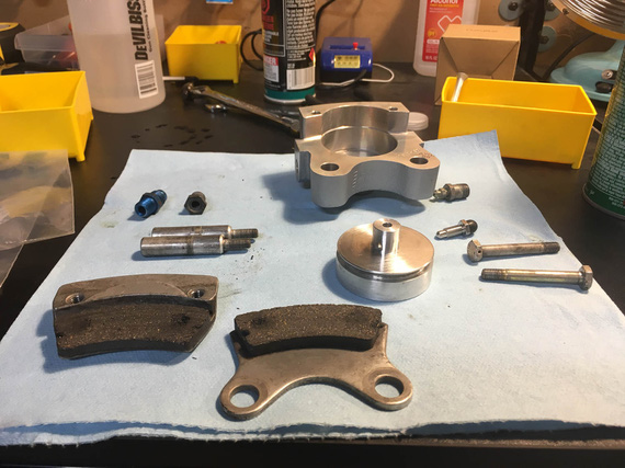
Cleaning up the parts
Now, I tried tapping the anchor pins back in, but was too afraid to mess them up. Finally, that was an excuse to go get me an arbor press!
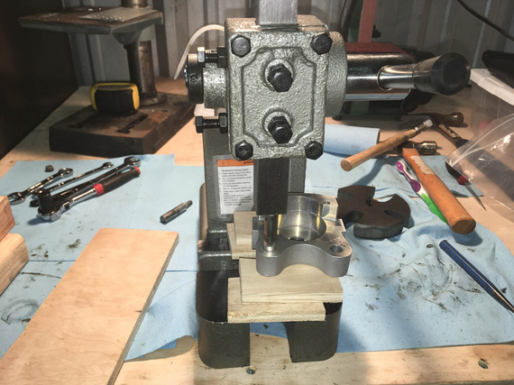
Pressing the pins back in
One final bit was to put the nuts back on.
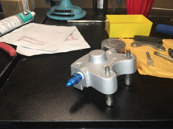
Ready for nuts
Question: how many wrenches does it take to put on an aircraft grade nut properly? Answer: three.
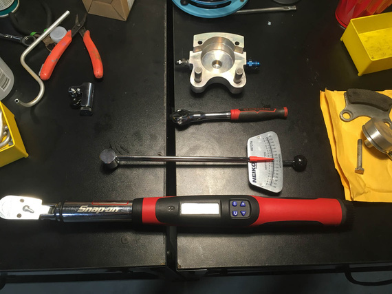
Wrenches!
Answer: three. Ratchet to work the nut before it's torqued. Small torque wrench to determine the free torque. Large torque wrench to torque to spec.
I pulled off the other caliper, and cleaned it up, too.
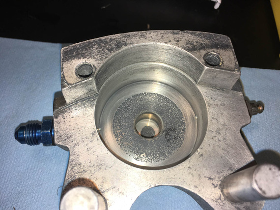
Left caliper, cleaned
Put in new piston o-rings, cleaned up AN flare adapters, put the calipers back together, and put them away.
Next step was,
The Parking Brake Valve
That little doodad was leaking for a long time, too. It seemed it was leaking from the little cam arm that rotates, but I wasn't sure, so I decided to put it apart and rebuild it completely, too.
It's under the passenger's seat on the Charger.
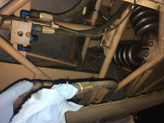
Pulled it off
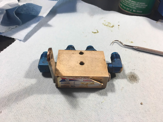
On the bench
First, I pulled the "cam arm" out - the little arm pivots, and pushes valves open (or lets them close) inside the box.
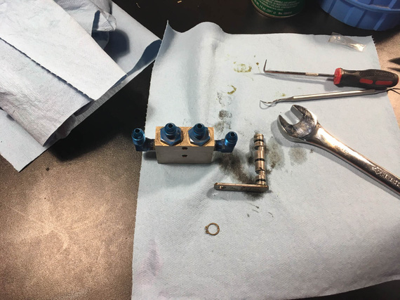
Cam actuating arm
O-rings were in reasonable shape, but looked a bit.. old. I decided to change them and disassemble the rest of the contraption, to change all the other o-rings in it.
Now, the middle two "straight" fittings are straight threads and o-rings under them. No problems there.
The two 90 degree elbows on the sides are NPT. One came out just fine. The other... Well, the other decided to leave a chunk of itself inside the valve body...
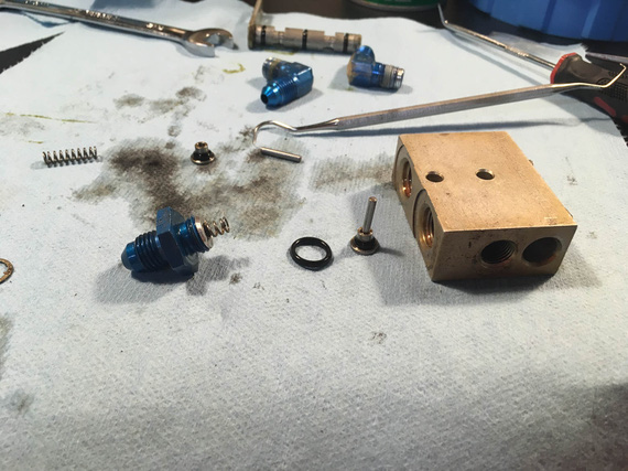
Bits and pieces - valves, springs, and actuator plungers
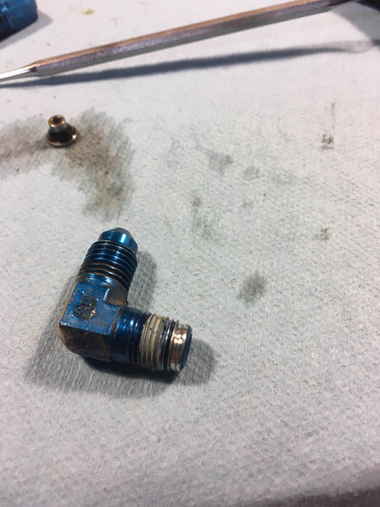
Busted elbow
You can see the chunk of the male thread galled and stuck in the female NPT hole of the body.
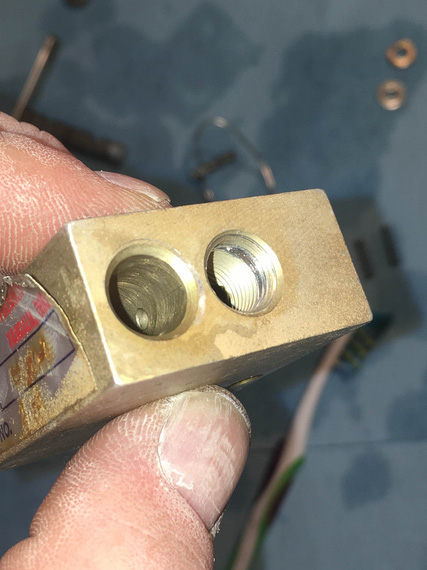
Chunk of thread
Damn damn damn! I need a new parking brake valve now?
That new valve is how much (search.. search.. six hundred and sixty five!?!?!?!?! $#*@(&(2@@#!). No way I'm paying that.
There are alternatives. Cheapest one is like what, hundred fifty bucks; and I'll have to work around it's plumbing (which is different than mine); and the "direct fit" "homebuilt" cheapest one is over $300? No way. No way in hell until I try to fix this.
What is the hole? 1/8 NPT? McMaster sells taps for $25, two new fittings are what... under $30, and a handful of o-rings, which of course I didn't have (I have a bunch of o-rings in a ton of sizes for fuel applications, but not for brake applications).
We'll try to re-tap that hole; hopefully braking the piece of the thread left in there by the fitting while keeping the female thread intact...
... the tap and the o-rings got delivered a few days later. Made myself some nice soft jaws for the vice to hold the thing without scratching it.
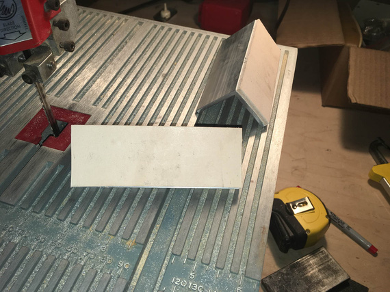
Soft jaws
That's aluminum angle and leather.
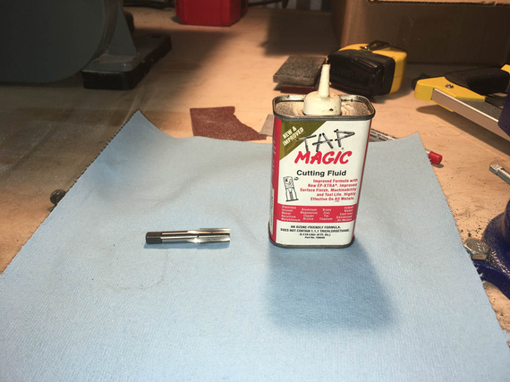
Weapons ready!
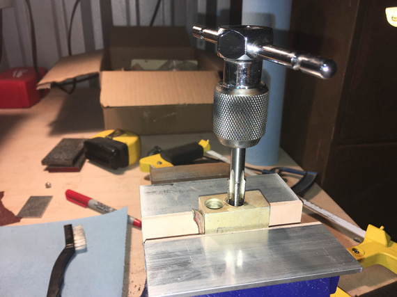
Tap, tap, tap (not that kind of tap!)
Slowly, slowly and gently, breaking the chip every 1/4 turn and adding cutting fluid. It worked out great! The hole was deeper than needed, so I tapped the threads a bit deeper, arguing that if the female portion of the threads got chewed up a bit, I'd put a fresh surface on them too.
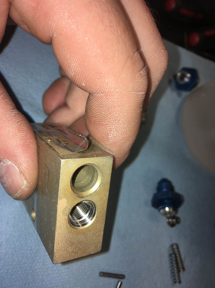
Done!
Well, we'll have to wait to see how well this works out. If it doesn't leak, I just saved me a boat-ton of money.
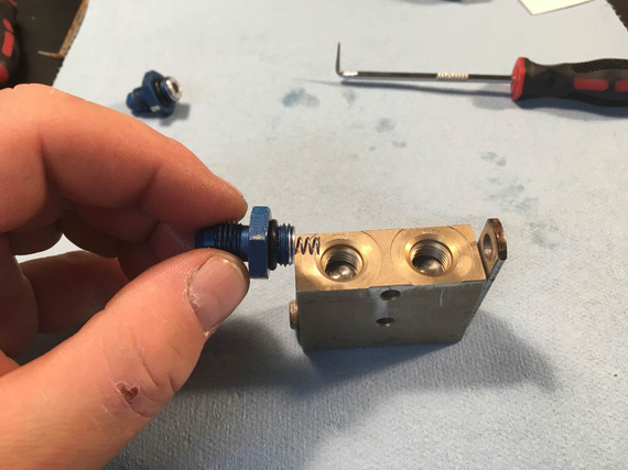
Putting it back together
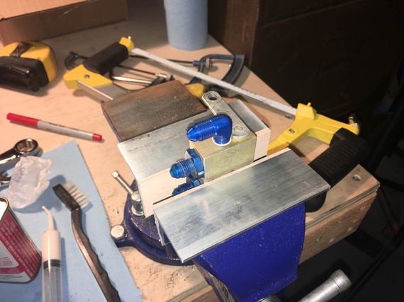
All done
New o-rings, new elbow fittings, re-tapped hole. Threads on the busted hole felt good, no hesitation and "catching". We'll see how that works out...
Next,
The Pads
Pads on the right brake (the one with leaking piston o-ring and busted caliper) were soaked in brake fluid. Cleveland says contaminated pads are a cause for replacement, so I decided to do it, since I was already in there. Besides, excuse for another tool - this time, the brake rivet set!
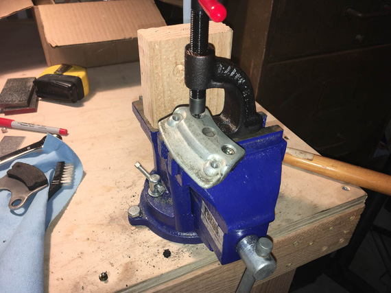
Punching old rivets out
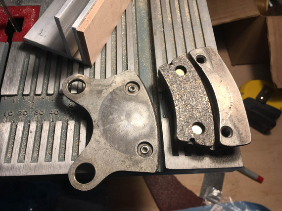
... and putting new ones in
And with that, the last bit before we could put everything back together was,
The Wheels
Again, since I was already there, I decided to do the wheels at this time too - re-pack the bearings, that is, and give the disk contaminated with brake fluid a real good cleaning.
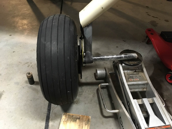
Jacking the plane
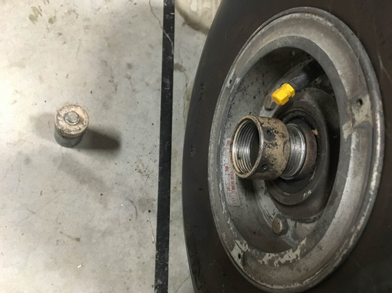
The axle nut comes off with finger pressure
I admit - I made a mistake here. I did not remember what kind of resistance I felt when spinning the wheel on the axle before I took off the nut and took everything apart. It would've been important, especially since this was my first time doing these wheels, and wheels in general....
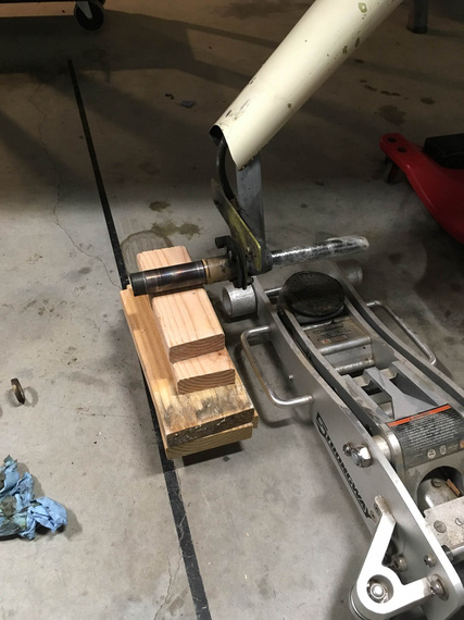
Temp "wheel"
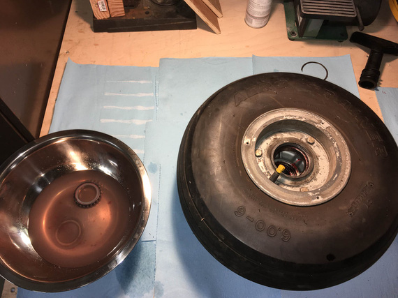
Cleaning bearings
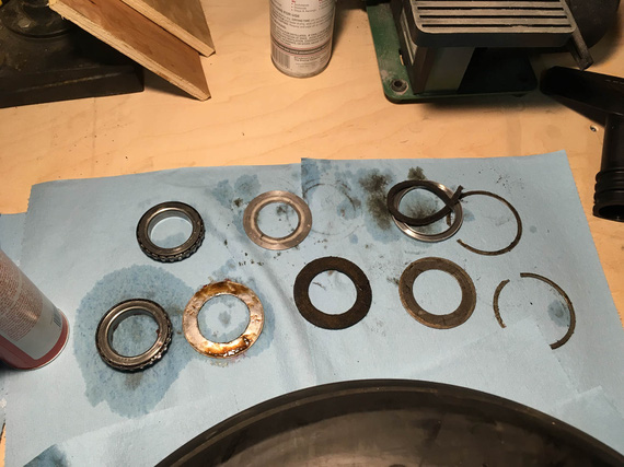
All the grease seals (and bearings)
Crap! What, the felt seal is bust!?.. Looks like it is. Okay, not finishing this part quickly (because of yet again, another "order parts / wait" cycle).
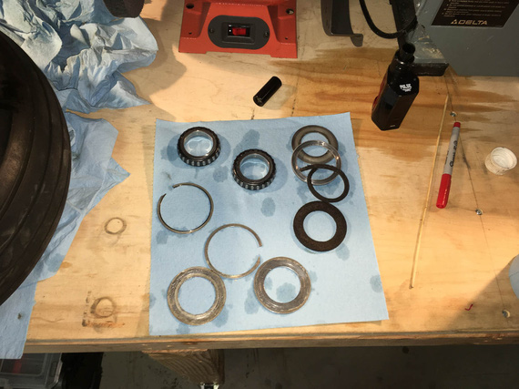
Flushed, and drying
Do you see the other mistake I made? Yep. I mixed up the bearings ("front" and "back"). Bearings should always stay with their races...
Oh well. After some research, seems that the worst that will happen is wear will get accelerated.. since the bearings and races looked squeaky clean, I decided to keep them as is.. for now. And just Hail Mary the position (since I have a 50% chance of getting it right :)).
I decided to replace all the felts because I was changing grease from I didn't know what kind but likely red Mobil grease to Aeroshell 22.
Ironically, I apparently didn't take a single picture of the bearings being greased - probably because my hands were too greasy doing them :). Oh well.
The new felts came, and got coated in grease.
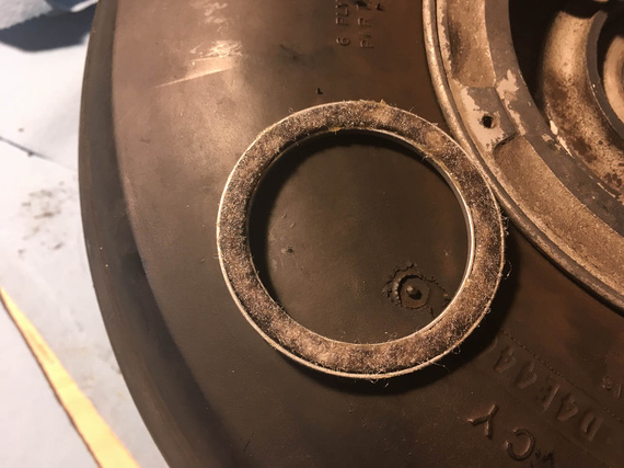
One of new felts
And, I put the wheel back together. And then... And then, I couldn't tighten it back right. I have to align the hole in the axle nut for the cotter pin... I could either get it under-tight (with perceptible play in the bearings - not good), or a bit over-tight (so that the wheel will spin, but with some measure of resistance). Remember, I said that my mistake number one was not checking how freely this wheel spun prior to pulling it off? Now, I was paying for it.
I tried flipping the bearings around (because I didn't note their original positions), thinking that maybe that will help. Nope. No change at all.
Oh well. I couldn't do anything about that at that point, so decided to settle on "a bit tighter" option.
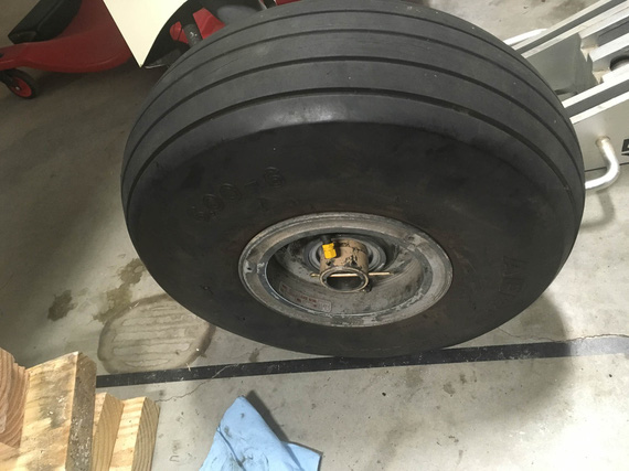
Cotter pin
With the other wheel, things went much smoother (the second time you do the job, it takes you 10% of time it took you to do it the first time, right? :) ). It came off, was cleaned, and got back on, with new felts and bearings in the original positions. Nut got tightened to super tight, loosened, and tightened to finger tight - and the wheel was perfect. No play, and no "drag".
Le double sigh.
So finally, it was the time to put things back together!
Putting the Brakes Back On
That was almost pleasant, after all the mess-aroundary with bearings. I cleaned up the pins' glide bushings, and lubed them with Dri-Slide (graphite + moly) lube Parker recommends.
And then... Calipers on, slide the bolts in, torque.
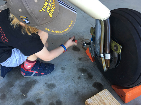
Putting calipers back on
Even a child could do it! By the way, that's the left wheel - remember I was mentioning the breather hoses routed to that wheel? There they are, in their awesome oil-spraying glory...
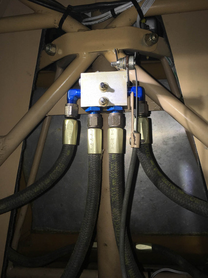
Parking brake back on
Put the parking brake back on.
Phew. Now, finally, we can bleed and test!
Bleeding
Now, there are two approaches to bleeding brakes - either bottom up (push fluid up thru the bleeder valves), or top down (sit in the plane and squeeze the pedals while the other guy opens and closes the bleeder). Bottom up is inherently simpler.
Some time ago, my buddy Dick was showing off his fancy bleeder he got from ATS.
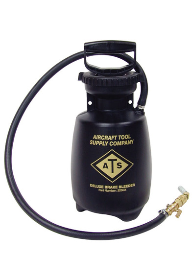
ATS Brake bleeder
Hmmm.. What is that reminding me of? Aha! Bug sprayer! That's right
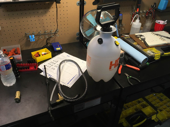
Bug sprayer
Now, a few minor modifications, and...
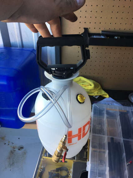
DIY brake bleeder
Pump it with air, open the valve, and the brake fluid gets pushed out thru the line that attaches to the bleeder valve on the caliper. Child's play.
For bleeding, I dragged my good friend Nick S. to give me a helping hand. I could've done this by myself, but having someone watching over the "other end" (it either being the end that pushes the fluid in, or the end out of which the fluid comes out) makes the job much more pleasant.
Now, the way brakes are plumbed on the Charger is, each side goes from it's caliper up the gear leg to the parking brake valve, then to the Master Cylinder, and from there both Master Cylinders are plumbed into a tee, from which the single line (the one I was re-making earlier) goes to the reservoir on the firewall.
We decided to bleed each side up to the tee first - to minimize the amount of air ending in the "common" line between the tee and the firewall. After bleeding each side up to the tee, we'd attach the "common" line and bleed each side up to the reservoir, letting at least a cup of fluid to flow thru, ensuring that we push all the air out.
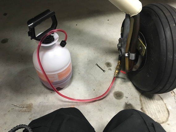
The setup
The plan went without a hitch, aside from the fact that I initially forgot to open the parking brake, and was trying to figure out why the hell the fluid won't flow. Hehe. Nick called it, too!
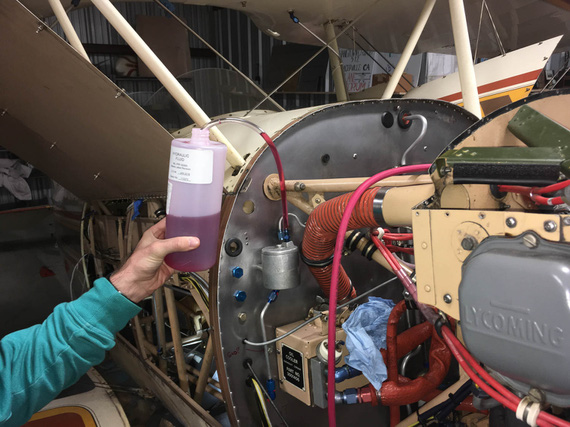
Nick holding the fluid line from reservoir
Finally, the moment of truth. The brakes were firm and nice, held well, and no leaks nowhere! Now, I need to double-check this - next time I'm in the hangar for a good few hours, I'll set the parking brake to keep the pressure in lines, and see what happens - but initially, everything held just fine! Phew.
So finally, the last bit was left.
Finishing the New Line Install
Now, the new line was finally in place, and all that was left was to install some ADELs to hold it.
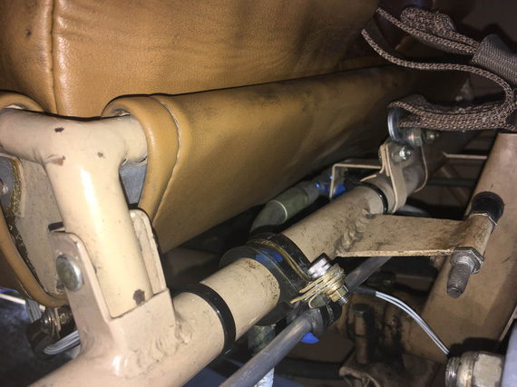
ADEL One
That one took ... an hour! Very nasty spot and hard to get to. I had to find a better way...
Now, there are fancy mods to ViceGrips (or you can buy them for sizeable chunks of cash pre-made) to hold ADEL clamps together while you're inserting the screw and starting the nut. I don't have them.
Some people use safety wire.
I decided to try...
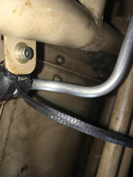
Lacing cord!
It works great, too! Just double up and "noose" it around - it holds a clamp like a charm in the "closed" position while you fiddle with the nut! Even Jack came out to see that.
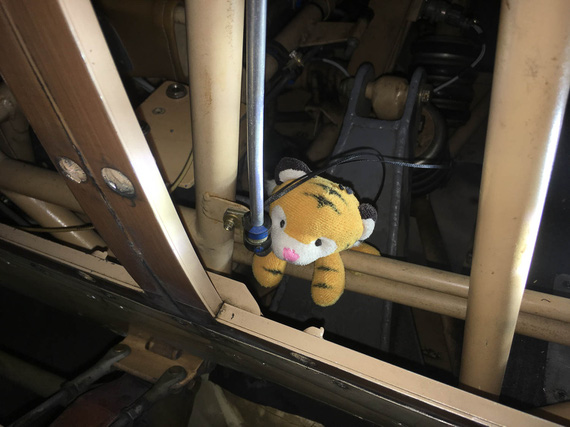
Jack inspecting the work
With those clamps installed, I had to tie a bundle of wires going across the tube to the front stick's PTT switch. That one was one hell of a contortion exercise, under the front seat's front edge and behind the stick, but I managed after a couple of tries.
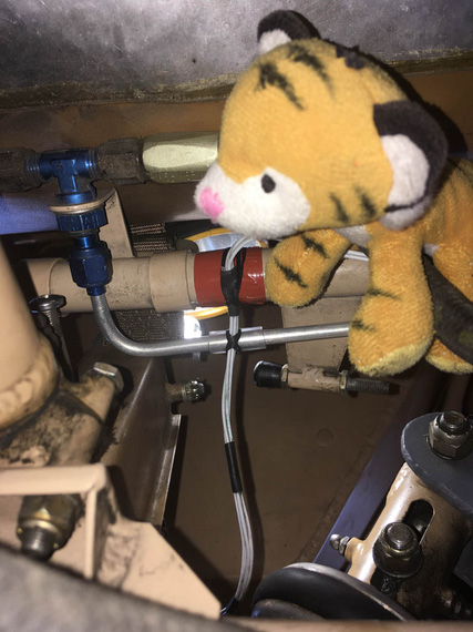
Lacing the wires to brake fluid line and structure
And finally, a couple more clamps along the length of the line on the fuse to hold it in place there. Some TorqSeal, and we're done!
I worked out a method to these, finally, I think. I use a long (~2 inches) AN3 bolt first to "thread" the clamps on, and then close them with a wrap of lacing cord using the "noose" method ("Method 2" here). I then remove the long bolt, install the final bolt, and start the nut. When the nut brings clamps almost to a close, I cut off the nooses, and tighten the nut. Works like a charm!
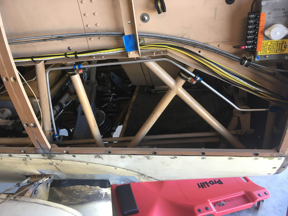
All done!
So, there. A pretty big job now complete - brake system rebuilt, re-bled, and ready to go.
PS: I was considering where to put this - under "2019 Annual" or "Electrical Rebuild" category... decided to pile it into the "Electrical Rebuild", because basically as a part of this rebuild I'm doing a bunch more stuff.. This is basically becoming a "minor restore" project... But still, the main theme is "Electrical Rebuild", and I'm keeping it under this section.
"you're gonna have to key the mike. I can't see you when you nod your head."
-ORD ATC
Up ↑
Bending Brake Lines
... and fitting in place
| On: | Sep 30, 2019 |
| In: | [Chickenhouse Charger] Electrical Rebuild |
| Time logged: | 12.5 |
| Tags: | 6781G, MA5 Charger, Annual, brakes, bending, tube |
So, yet again, last few weeks turned into working on lots of little bits simultaneously.
But, finally, one of them is done - and therefore, something to log.. ahem, pardon, b-log, about :).
The brake line.
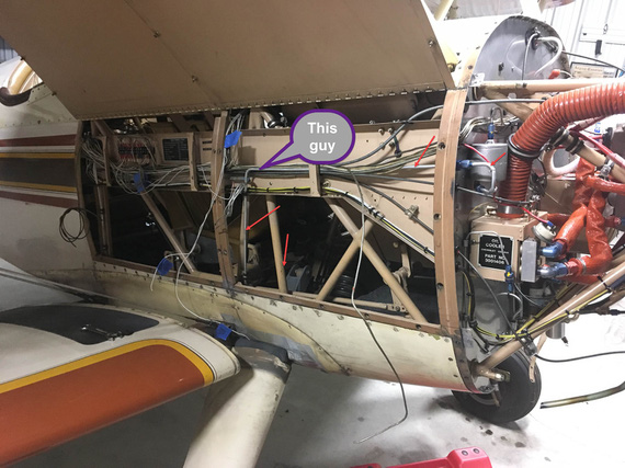
The old brake line
I needed to relocate this bad boy to free up room for the Voltage Regulator. This is the older picture - I have long bent it out of the way and cut off a chunk. It was to be relocated to run below the conduit.
Well, first, we had to locate the hole in the firewall. And that depended on the line to the reservoir, firewall forward.
After having thunk a bit about it, decided to replace the 90 degree fitting in the reservoir with the 45 degree; and the firewall bulkhead fitting with a 90 degree. That'd minimize the amount of bends and make for a neat job.
So, firewall forward we go first - that will locate the bulkhead fitting and the hole.
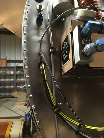
Mockup one
This is with old fittings in the firewall and the reservoir. The clamp on the mockup line is using an existing hole in the firewall - nice happenstance; I'd have to plug it with a "blank" bolt otherwise.
Then, "project" the tube onto the firewall, roughly mark the center, and drill!
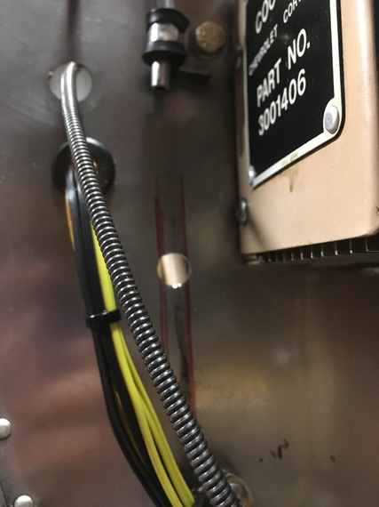
New hole!
And now, to the most fun part. Making the tube.
This was another first - never done tubes and flares before, so first of, had to figure out how to flare them properly.
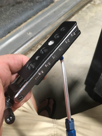
Flaring tool
Question: by how far does the tube have to stick out of it to arrive at the correct size flare?
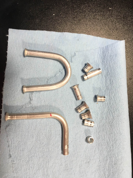
Practice (evidence)
Answer: 0.035. For the -4 tube. :) Yeah, those practice flares are not ALL the ones I made. Just some of them.
OKay, so the next question was how to actually make it fit.
My first thought was,
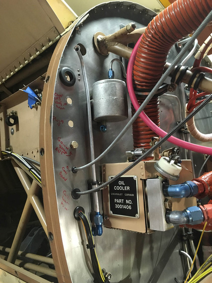
Bottom hooked up, top not bent yet
- Hook up the long portion (bottom)
- Mark out the centerline of where the bend should be
- Bend
The tubing bender has alignments marks for where the marked CL should go for different angles of bends.
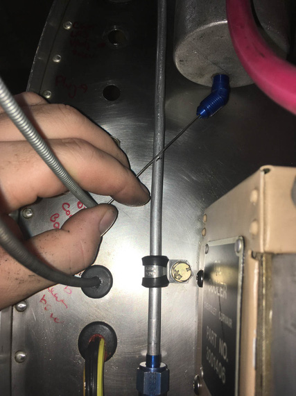
Marking centerline
What I didn't realize is that on this short a run, even a little error (bend being off of the ideal centerline by as little as 1/16") would cause a total misalignment.
It did, of course.
Okay, second try.
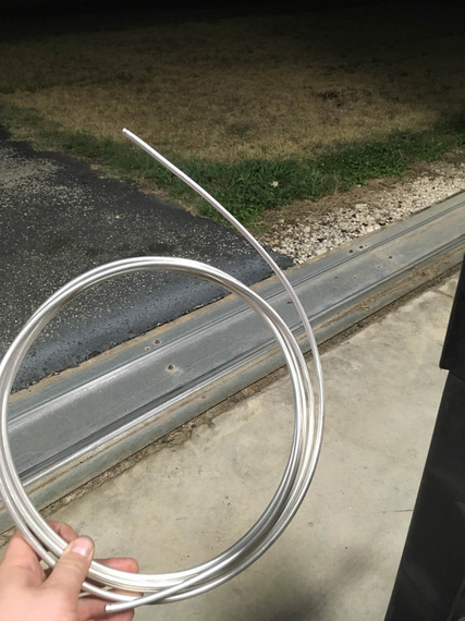
Real material!
I pulled out the roll of the new tubing, too. Partly to motivate me. Partly because I ran out of the chunk I've cut off of the old line.
This time, the idea was to bend it first and get the bend angle just right. Then, trim to correct length.
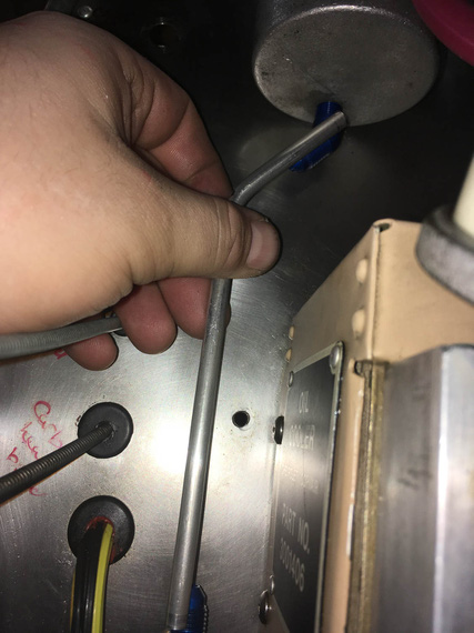
Bend angle first
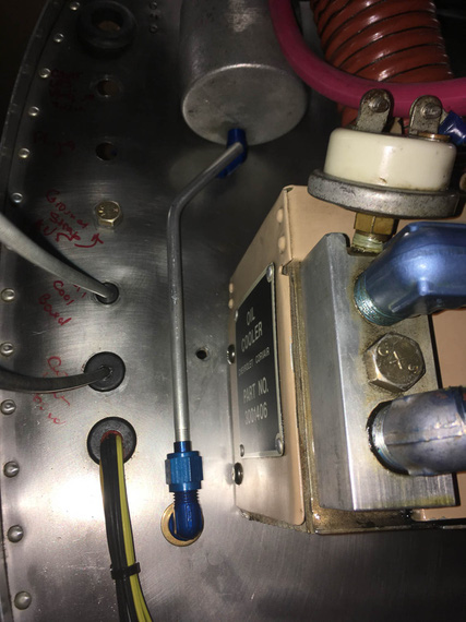
Trim, flare, hook up the bottom and mark the top
This actually worked.
Question. If you have a fitting with a flared end, where to place the cut mark, so that after you cut, and deburr, and flare it, while it's sticking out of the flaring tool (un)-precisely 0.035", it fits?
Answer? I don't know. I think I got lucky :)
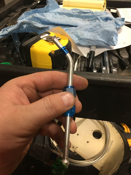
All done
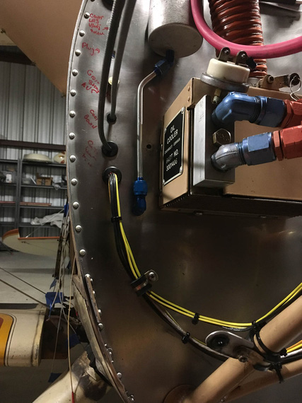
Installed
It fits perfect. I have no idea why the fitting there looks crooked - probably weird camera angle. It's straight :).
Okay. Time for the Big Kahuna - the actual long line, running along the conduit, and under passenger's seat.
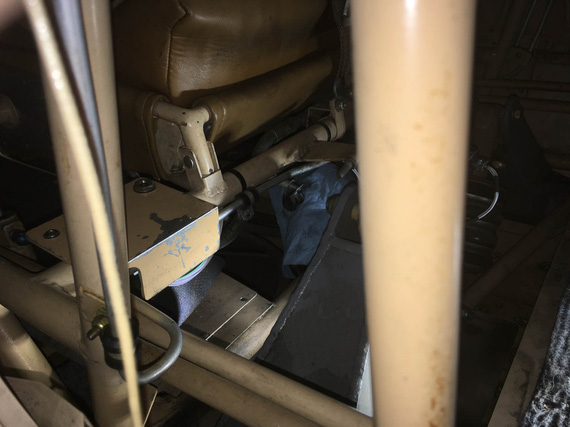
Under the seat it goes..
See that line? It goes down, turns, turns again, and again, and then goes to the center of front seat's front, and goes under.
It was rubbing against structure in a spot, too - so I wanted to clean all that up.
~30 minutes of head scratching yielded clamping arrangement that would work.
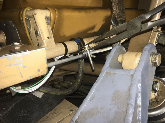
Clamps
By the way, I am stealing this arrangement shamelessly from my friend Mr. Gary Vogt of AuCountry Aviation fame. He uses similar arrangement to organize wires along motor mounts. Genius, really - and I have never seen this before (but I likely am a total idiot, anyway).
One final mock-up, and we're good to go.
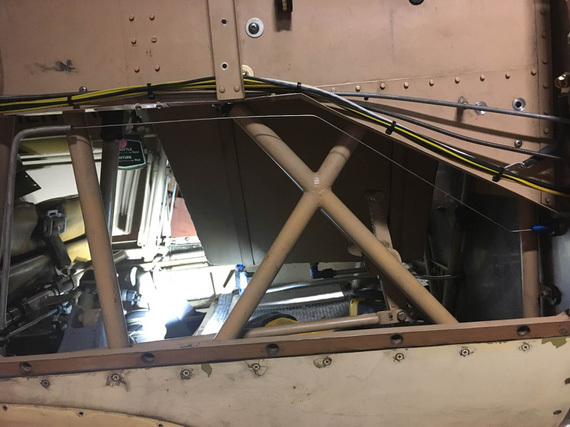
Safety wire for mockup
BTW. How do you make safety wire straight? Chuck it into a drill, and spin a bit :). It'll work harden a touch, and straighten out.
Okay, now, let's do the actual new line.
Unbend a long enough piece of tubing from the roll. Pull out the old line. (and use it as a template!)
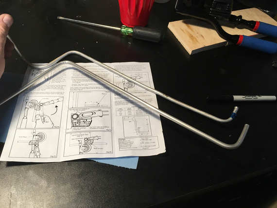
First two bends
Old line on the top, new on the bottom. I made the "tip" (that first section on the left) longer and planned to flare it later - can you guess, will that bite me or not? ;)
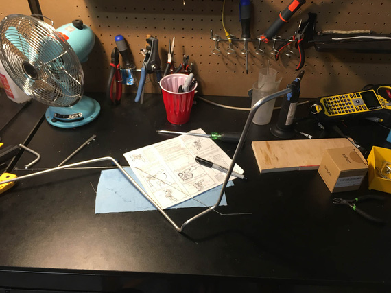
Getting close
Once I got to the point where the complex section (the one that goes from under the seat, to the side of the plane, and then up, and down again to run parallel to the conduit), it was time to try it on.
Maneuver it in.. it fits! Perfect! Bends clear all the right spots and fit in all the tight places.
Okay, now, time to actually attach it to the fitting under the passenger seat, hook it up with temp clamps, and do final bends and trim to final length in place.
But first, I need to flare that end - the one to go under the seat, where I left somewhat a longer stub to be trimmed later.
I trim it. Perfect length.
Crap! It does not go into my flaring tool now. It's way too short for it. WAAAY too short.
See, the flaring tool has some thickness to it. The sleeve has to fit on the tubing before you flare, and takes up another 1/4" of it's length. And, it won't go thru the bend. So there's a certain minimum length of straight tubing required for you to be able to flare it.
And, I already cut it off :( And I can't unbend it - it'll just break.
Okay, I'll admit to this. I did try to unbend it. I annealed it back to soft (torch + sharpie as temp indicator) and actually did succeed at it. But, bend flattens the tube some - and the sleeve still won't go over it.
Besides, bending this big Kahuna was actually not that hard - much easier than I thought, with old line acting as template. And, I had enough tubing. So, I decided to re-bend a new one.
Second try, I flared first. And then, I realized that Remo has probably bent his with a different kind of bender, or had a different kind of flaring tool - my bender would make that first section a bit longer than what the original line had.
Well... it wouldn't interfere with anything (I checked). It'll make it run a bit at an angle, and stick out from the seat a bit more... a bit uglier, but not a big deal (and I'll try to massage it into a bit more parallel run during final install).
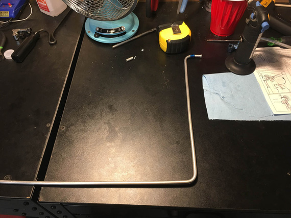
First bends - the first section (with sleeve and flare) is longer than original
Oh well.
Finished bending it, and installed it into the plane.
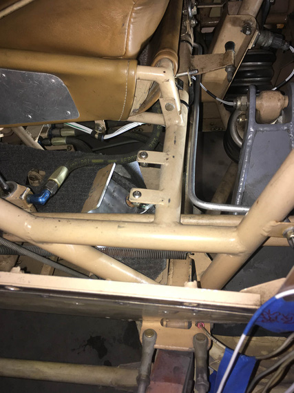
Seat to side...
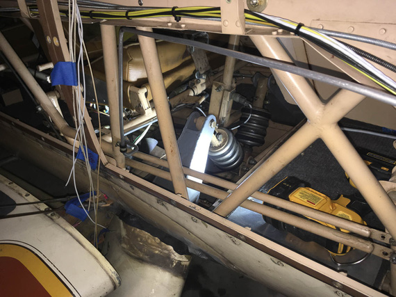
...and up the side
By the way, this is how this looks from under the plane.
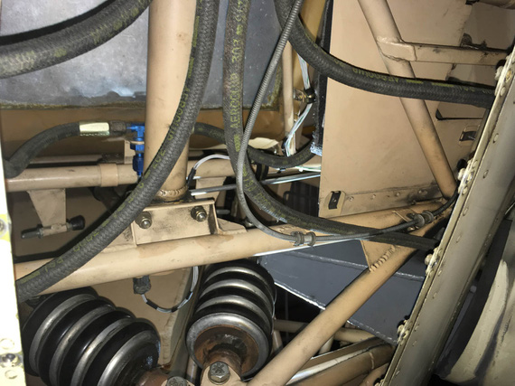
From under
The "front" of the plane is on the bottom of the pic. Can you find the line? (hint - it feeds the T with hoses attached to it. Hoses go to master cylinders under rudder pedals).
OKay, so now to final bends and trimming.
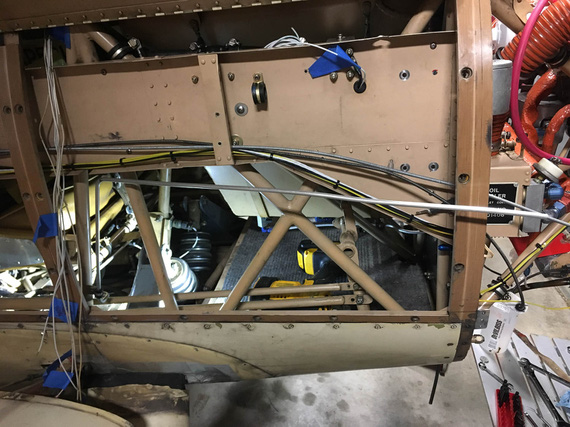
Still needs to be bent and trimmed
There'll need to be two more bends - "down" to follow the conduit and "out" to hook up to the bulkhead fitting on the firewall.
That geometry would need to ensure that I have enough straight tube to successfully flare it - learned my lesson there :).
So, our little safety wire mockup to the rescue.
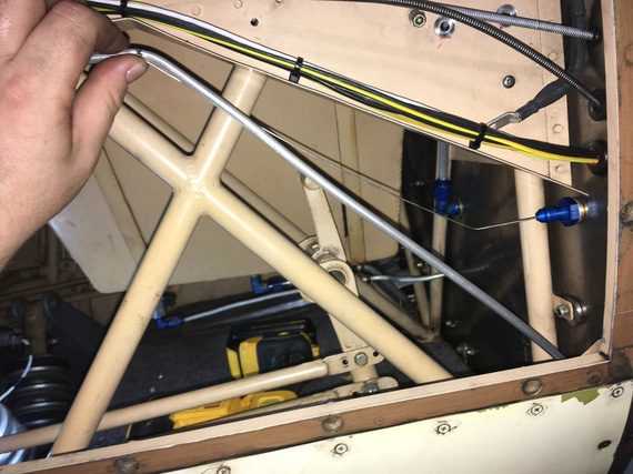
First bend made, marking / eyeballing the second
What I didn't realize is that this long line is much easier than a short stub. Even if you make a mistake, you can massage the line into compliance, "smudging" your mistake over the whole length - mistakes like wrong angle, a bit short here, etc.
Though, marking precisely does help. :)
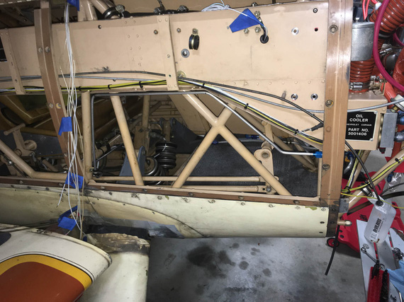
All done
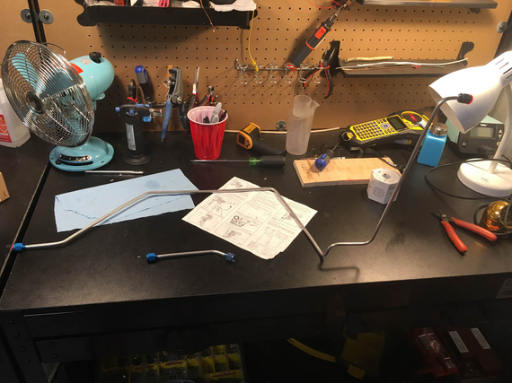
Two new tubes, all ready
I guess, mounting and bleeding is next; but for that, I need to replace the busted cylinder on the wheel, attempt to fix the leak in the parking brake, and re-pack the wheels (or I'll be re-bleeding the brakes later). I want to install the voltage regulator first, too, because that will minimize me messing with fasteners in the vicinity of this line.
Oh well.
PS: at the time of this writing, I am actually more than 50% thru with both of finishing up brakes, and voltage regulator. :).
"Approach, what's the tower?"
"That's a big tall building with glass all around it, but that's not important right now."
-ORD ATC
© Copyright "79FT". All rights reserved. Feel free to cite, but link back to the pages cited.
This website only shows how I did things in my various projects. These pages are for information and personal entertainment only and not to be construed as the only way, or even the perceived correct way of doing things. You are responsible for your own safety and techniques.