[79FT]: Building Things |
 |
Drag Wires, Aileron, et al
completing and refining
| On: | Sep 01, 2014 |
| In: | [Skybolt] Wings |
| Tags: | CAD, lower wings, ailerons |
Another week and a half. Did a ton of little things; each one of which took a ton of time, with seemingly little result... I guess, devil's in the details.
It's constant tweaking and tuning of things that takes a bunch of time. But, at this point, most of the rough things are in, and it's that tweaking and tuning that's left to do...
Oh well.
Drag Wires: done.
Finished all the drag wires. Initially I did an incorrect layout from the standpoint of which wire passes over which (or under which, depends on how you look at it). Apparently, I came across a definition of drag/anti-drag that's exactly the opposite of how the plans define them... Sigh.
Wires have to cross inside the drag wire blocks and inside the spar; so one has to go over and one under, like this (lots of transparency here):
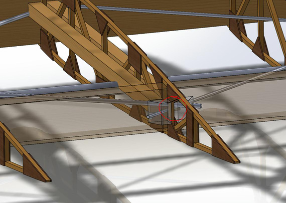
Drag/Anti Drag Wires Crossing
That's the pattern I did wrong; causing some interference with the bellcrank and heavy interference with rib diagonals.
Thanks to my original post on drag wire blocks interference in the aileron bay, and the picture Ward posted in that thread, I figured the wires pattern out. Switching it around made for much better clearance!
Also, my original problem with aileron interfering with the drag wire blocks is apparently no problem at all - I'll just relieve them (rasp, file, sandpaper, whatever) to provide clearance.
So, here's what the wing looks like right now:
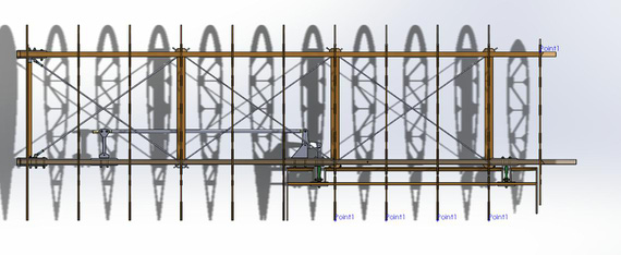
Latest wing with all the drag wires
Aileron Bay and Drag Wires
... and then, something I spent quite a number of hours on. You see, I want to sheet the inside of the aileron bay with curved piece of 1/16th plywood, supported on braces joining ends of the ribs together.
A few pictures below show the idea:
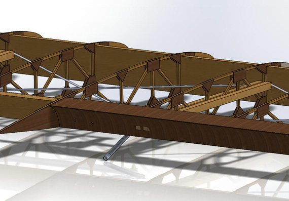
Aileron Bay Sheeting. Grain orientation is off, I know :)
This shows the support brace between ribs, just one for now.
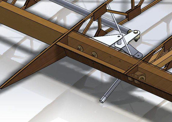
Aileron Bay Sheeting, showing the support brace.
This is all very rough. The problem though was this.
Here's how it looks from the wing tip side:
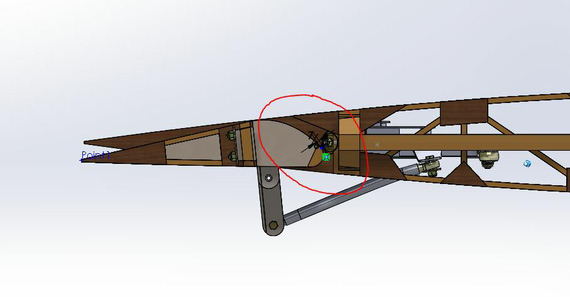
Aileron Well, looking from the tip, zoomed out
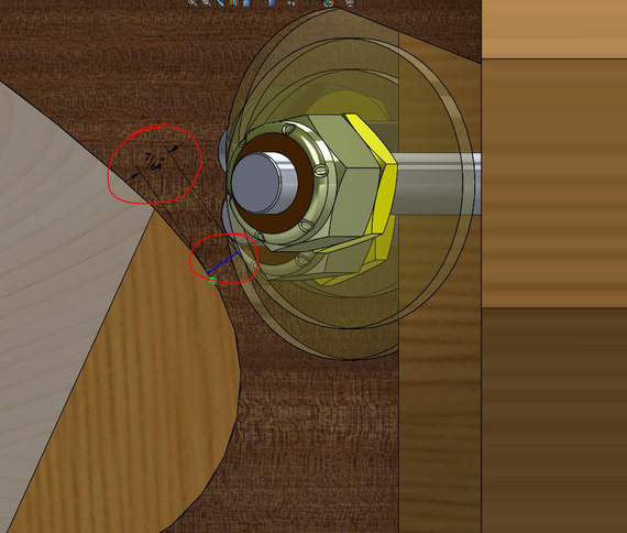
Aileron Well, zoomed in.
See that clearance??? 7/64ths between the aileron tip and the nut! So even before I started figuring out the best spline curve for that sheeting, it was obvious that it won't clear... 1/16th ply + 1/16th gap is already a 1/8th, or 8/64ths!
Asked the Biplane Forum folk in the same thread... And, separately, actually figured it out - it was suggested to use two thin jam nuts there instead of a thin + regular nyloc.
That cleared a lot of space up!
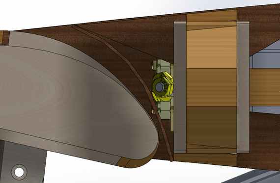
Finally, some clearance!
I was thinking about modifying the tails of the wing ribs in the bay area to support this sheeting.. But, even with thin jam nuts, the bay is still very tight. Given that I won't be able to build exactly to perfect dimensions, I finally decided not to bother, and just build in place (and then we'll see what clearance I really will be able to get :)
Backup plan? Have some drag wire hardware protrude into the bay, and sheeting be not "in front of it", but somewhat behind it (closer to the main wing spar). Something like this.
And with that, I moved on to
Cleaning a lot of things up
Added all the hardware to the aileron hinges. Cleaned up most of the compression plates (doublers) to go around the compression struts and drag wires.
Oh, and apparently, my aileron hinges were drawn a bit wrong (and had that unsightly early model of Fafnir rod end I have thrown together). Fixed that. Made them pretty green color to celebrate the occasion :).
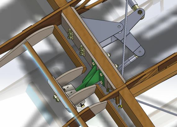
All pretty and correct hinges with HW
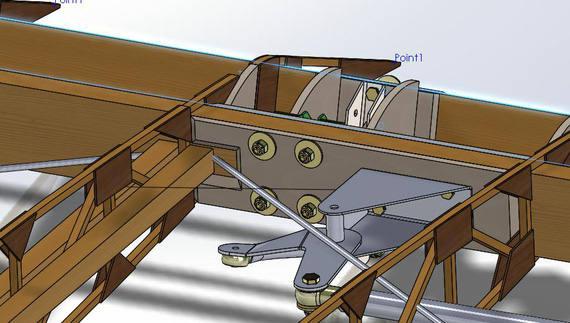
Compression plates relieved for the struts and drag wires
Interference
As I expected. Drag wires don't clear rib's diagonals in some places.
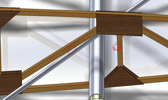
Station 24 vertical and diagonal interference.
Hale Wallace in his notes suggested to relocate station 24 vertical to 23 3/4, 1/4 inch forward (or "left" in the above picture). This will make the diagonal more steep, and clear the drag wires. I'll have to do that.
Another nasty. I was ready for this, and, sure enough, the bellcrank/idler pushrod doesn't clear the compression struts. The idler will have to be made lower; Steen bends them downward and I will see if I can avoid that by just moving it down a bit (and moving the idler arm down on it's bushing).
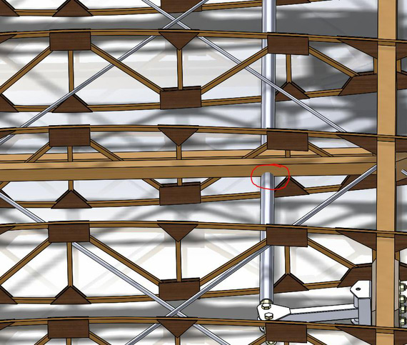
Pushrod not clearing compression struts.
Ribs
So, I started looking at relocating that vertical first.
My ribs' models are the first ones I did in Solid Works; and they suck. They are made off of sketches created from converted AutoCAD files, with lots of ugly things in them. They are practically unmodifiable. Back then I thought it was easier to draw things in AutoCAD and import them to SWX - oh, what an idiot I was :).
Also, while looking at things, it became clear that they also are not sitting right on spars (not symmetrical to spars' center plane basically).
It feels like I will end up re-drawing them from scratch, and doing them as proper assemblies this time. We'll see.
It might well be that the problem I was having with aileron-to-other-ribs-alignment will go away, and no holes will need to be relocated...
It's annoying, but at this time I am so much better with SWX than back a year ago when I was doing ribs. Still, Le Sigh.
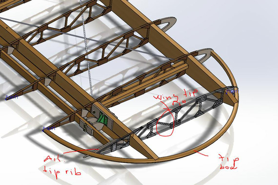
Aileron Tip Rib, Wing Tip Rib, and Tip Bow
I've been putting this off, since those tip ribs are not dimensioned on the plans, and aren't a standard airfoil. They're supposed to create a nice transition from the main wing panel into the tip bow, creating some nice curvature.
I had the wing tip rib drawn up approximately, just as a placeholder.
Yesterday, I did an approximate aileron tip rib as well. Cutting it out of the plan and super-imposing two patters on one another helped! Plans are off (dimensions marked on them are not matching the dimensions measured off of them), but at least they're off uniformly within one sheet; allowing me to do this. It shows what's where.
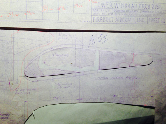
Tip Rib, cut out - finally, some physical work on the "plane"!
Well, for one, it became obvious that the top aileron skin on the leading edge will have to create a compound curve going to the tip rib.
Searching thru the Forum, and reading things showed that apparently it's not that big of a problem. Gradual gluing and lots of clamping pressure should solve that one. :)
And then, there's the overall tip rib shape.
Overall setup.
This is all very early with no "trimming cuts" made, obviously.
If you think about it, the aileron tip rib is supposed to be a bit "beefier" ("taller") than the wing tip rib. The tail of the aileron tip rib in the place where it's touching the bow should be 3/4 inches tall (so that it's flush with the bow).
All that will create nice smooth "flow" of curves from the last "full size" airfoil section (created by the wing rib and the aileron rib) into the tip ribs and tip bow.
So, first thing I'm not sure about is how good my tip rib (wing rib that is) is. I think the aileron tip rib should "play off" the wing tip rib's shape... In fact, if you lay a straightedge between the tip rib and the aileron rib with aileron positioned at 0 degree deflection, moving that straightedge should define the form of the aileron tip rib. I will do just that, later, lofting the surface that will "cut" the aileron tip rib out (and use a real straightedge with some sandpaper glued to it to shape the actual aileron's tip rib). I love it how CADing makes you think about these things!
But! That requires me to have a nice wing tip rib. Which I don't have. So to that task then, first.
Skybolt plans have the general outline and no grid on them. It's not a standard airfoil. Hmmm...
Last time I did it, I took dimensions off of plans. It turned out a bit off shape-wise if compared visually to the plans, so I tweaked it a bit. I still don't like that tip rib.
To the Firebolt!
Firebolt, by the way, is Skybolt, "improved" (and by that I mean added weight). Fuselage is a few inches longer, and hardware is all different; but basic wing design and overall things are the same. It makes it a great reference to read thru and see how things are done there.
Firebolt's wing tip rib is located at the same station as Skybolt's. That gives me some hope :).
Firebolt plans are also off (print dimensions not matching actual on sheets), but at least they have the grid -- amount of error accumulated over 1 inch of measurment hopefully is negligible. We'll have to see.
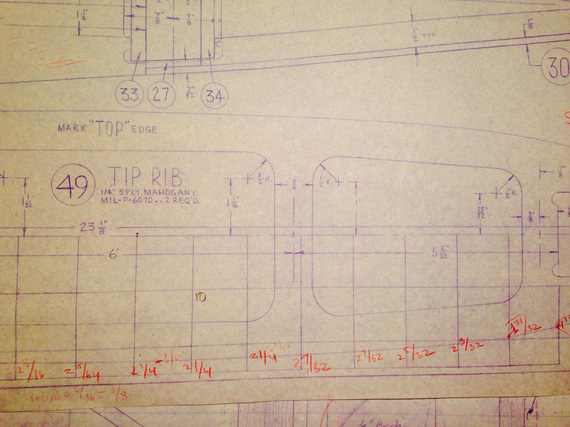
Dimensioning the Firebolt plans
And after going thru about half of that dimensioning, I decided that it's actually time to write this B-Log post, and take a break :).
I'll be bending some more sheet metal tomorrow. Post on that coming up!
Every one already knows the definition of a 'good' landing is one from which you can walk away. But very few know the definition of a 'great landing.' It's one after which you can use the airplane another time.
Up ↑
© Copyright "79FT". All rights reserved. Feel free to cite, but link back to the pages cited.
This website only shows how I did things in my various projects. These pages are for information and personal entertainment only and not to be construed as the only way, or even the perceived correct way of doing things. You are responsible for your own safety and techniques.