[79FT]: Building Things |
 |
Bellcrank and Idler
Bending and twisting virtual metal
| On: | May 22, 2014 |
| In: | [Skybolt] Wings |
| Tags: | CAD, lower wings, control system, ailerons |
It's almost 5 am and Im finally done with the bellcrank alignment! Phew.
By the way, sheet metal stuff in Solid Works is amazing! You give it the bend lines, radii, and a couple more parameters; and it automatically creates both the bent item; as well as the flat pattern. Print the pattern, glue, and start bending -- it will show you which line, how many degrees, and in which direction to bend. Ill post one of those final drawings later, when I get around to printing them and bending some actual metal :).
Anyway...
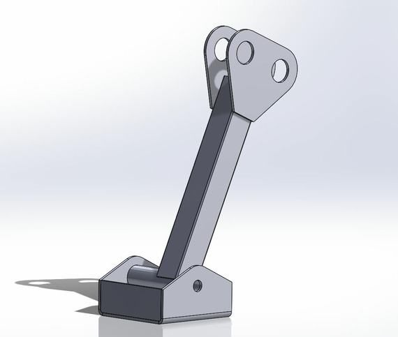
The night started quite jolly with me whipping out the idler arm with it's bracket. Looks pretty neat, eh?

Aileron Idler Arm and Bracket
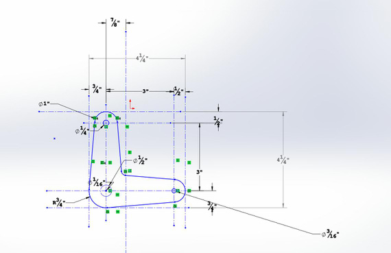
And then, back to the bellcrank hell. I had it modeled back in the days, and the "jog" bend 1/2 inches down made. Here's how busy the sketch with all the radii and holes looks BTW; pre-bending.

Bellcrank layout
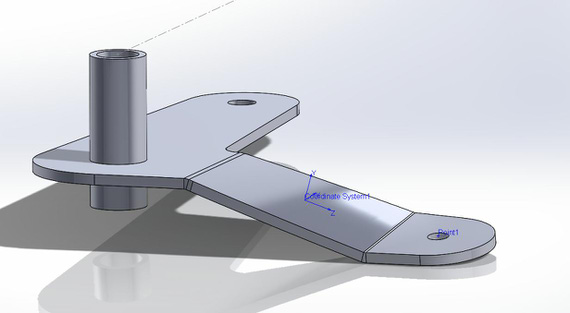
Anyway, with all the sheet metal awesomeness SolidWorks doesn't know how to twist. You can twist a model by using deformation, but at that point all kinds of shenanigans begin to happen. For example, all faces of the model stop being planar faces (meaning nothing can be sketched on them, and sketch is how you start defining a feature (part of the model)); for some reason I wasn't able to put a reference point into the center of one of the holes, etc. (I ended up drawing that point finally by projecting that hole's centerline onto one of the faces; that did work for whatever the weird reason Solid Works gods must have).

Bellcrank, bent and twisted
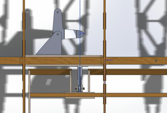
And after fiddling with it for about an hour, I was finally able to position everything. The plans don't specify where the bracket should be, so my educated and logical (yes, mr. Spock?) guess was that it should be so that the aileron pushrod connecting bellcrank to the alieron hinge is aligned and straight in the "aileron neutral" position. So I used the aileron hinge center as the reference; squared the bellcrank and aligned it that way. Note the blue line (that's actually a plane bisecting the aileron hinge), and the Point1 (that's that wretched point on the twisted surface that took me so long to figure out). That's what I used for alignment.

Bellcrank mated and aligned with aileron hinge
Coming up, putting in the idler, all the pushrods, and checking clearances with rib truss throughout the full range of motion. I strongly suspect that I will need the control stick's model on the fuse to do that, since that's what the other end of that pushrod attaches to. Oh man... gotta love those dependencies. That just means that I will have to do that model earlier than planned. Oh well. I like Solid Works anyways...
Tomorrow's the Shop Day! Gotta clean and put that compressor together.
OK 5:11 AM; time to go get some sleep :)
Flying at night is the same as flying in the day, except you can't see.
Up ↑
© Copyright "79FT". All rights reserved. Feel free to cite, but link back to the pages cited.
This website only shows how I did things in my various projects. These pages are for information and personal entertainment only and not to be construed as the only way, or even the perceived correct way of doing things. You are responsible for your own safety and techniques.