[79FT]: Building Things |
 |
The Flying Fire Hazard
...sparks galore!
| On: | May 16, 2019 |
| In: | [Chickenhouse Charger] Electrical Rebuild |
| Tags: | 6781G, MA5 Charger, Annual, electrical |
This thing nagged me for a while. The Charger did not have the Field breaker. For that matter, it didn't have the Alternator master breaker, either.
It had this weird "main buss" breaker for 60 amps, but that didn't look like the Alternator breaker to me.
So in between dealing with other things after having decided to put her thru Annual in 2019 a bit early, I was running around with my multimeter, tracing wires.
Initially, I quickly discovered that some lines were definitely not fused; like Battery -> Main Buss line, and thought I'd put inline fuses into them, and be done.
She has an old charging system; a mechanical switching voltage regulator, and a Delco Remy alternator seemingly from a tractor:
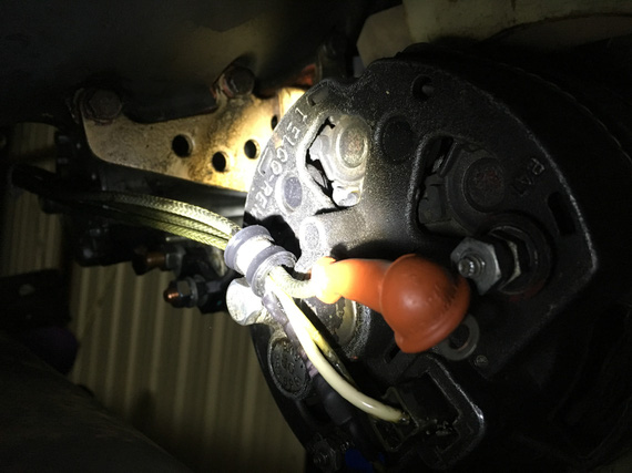
The old Delco-Remy
Voltage regulator didn't make sense. It had 4 wires (should be 2: supply and field output, or 3: supply, sense, and field output).
Alternator didn't make sense. Instead of 1 wire for Field input, it had two wires.
Additionally, Battery Contactor didn't make sense. One terminal had a wire going to it. The other was grounded....
Interlude
Battery Contactor is an interesting point here. Normally, one terminal is connected to the "always hot" side of it (basically, directly to the battery) and the other goes to the Master Switch. Master Switch turns the Battery Contactor on by grounding that wire, providing the negative side to the circuit. It's a safety thing. If that wire breaks, it'll either turn the electrical off (open circuit), or it will keep it turned on (short to ground). That's it.
But, one of the terminals on the Battery Contactor was grounded... that means, that the other terminal (the wire coming from the Master Switch) must provide positive side??? Huh? But where does it get it's power from?
Tracing
So to tracing we went. I spend maybe 10 hours trying to find diagrams and understand that alternator and voltage regulator hookups.
And me tracing it spelled my doom.
The Diagram
Now, I didn't trace the rest of it. Just the main distribution system. That was enough.
Shall we?
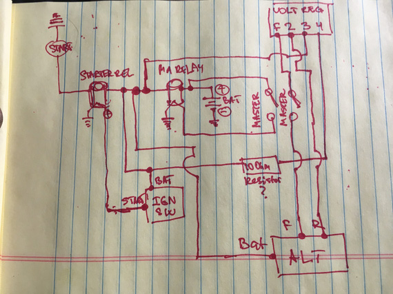
The current main power system of the Charger
Yep, the diagram is missing the main power buss. It's dangling off of the same spot where everything else that's interesting is - the Battery Contactor (marked MA RELAY) <-> Starter Contactor (marked STARTER REL) link.
So let's see what we have here.
- Lots of unfused wires. Do you see a single fuse here? Nope. That's because there aren't any. All the fuses are further downstream, off of the main buss.
- Voltage Regulator has this extra wire running to / from cockpit that isn't really necessary and could've been kept on the hot side of the firewall (terminal 4 wire)
- Alternator field broken at output (F->ALT) rather than at input (battery -> terminal 3)
- And the best part? Always hot wire that you can't turn off between the battery and the Master Switch to turn the Master Solenoid on.
That last bit bugged me. I couldn't find the damn thing. Even before actually tracing it, I knew that if the Master Solenoid is switched on the "hot" side, it needs to get the power from somewhere, and that only could be battery. But I didn't see any wires on the always hot side of the Master Solenoid. Only when I traced it, I actually traced the physical wire to where it goes, and then found it. It was so tucked behind the battery -> Master Solenoid wire that it was invisible:
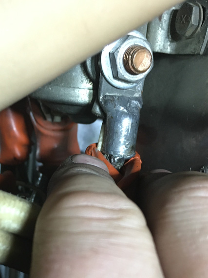
This little !@#!S@#....
Oh; and by the way, the Master Switch is the only switch that's soldered in, and w/o any good insulation around the terminals, and over-stripped wires. So that's just waiting to short, and the magic smoke that'll be let out behind the panel when that shorts can't be stopped (always hot wire, remember?)
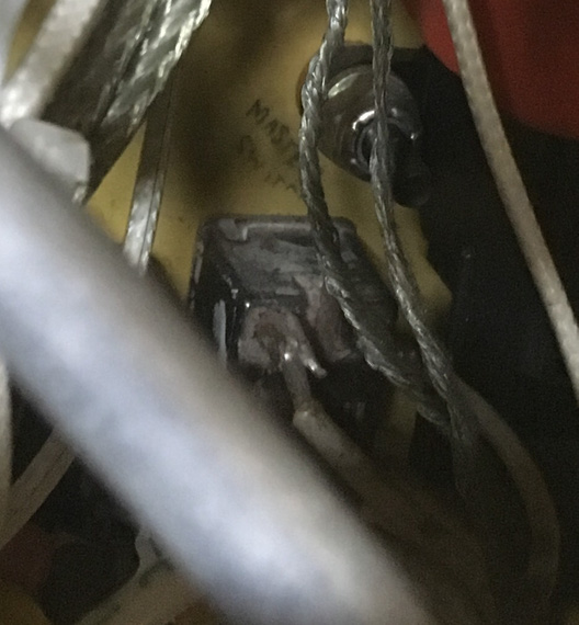
Master Switch
The Wires
So I kinda went backwards here; but I thought it'd be easier to see the diagram first.
Let's see.
Most of connections are made on this very nicely marked terminal block:
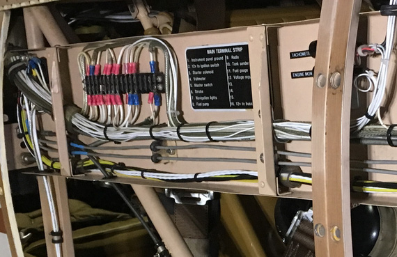
The terminal block
All the switched power comes out there, and every wire is marked. This actually helped a lot in tracing. This block is on the side of the plane, right next to the front hole's backrest.
You know what threw me off the most with that damned always hot wire (I ended up tracing it physically)? It's how it's hooked up.
Yep, it is hooked up to that terminal block. To the terminal... that is marked.. (drumroll).... "Master Switch".
Wait.. this actually makes sense... But where's the "return" from the switch?
Ah! It's the wire that's marked.... drumroll... "Fuel Gauge"!
So really, let's look at what's going on, shall we? Zoom in the image below, it's annotated.
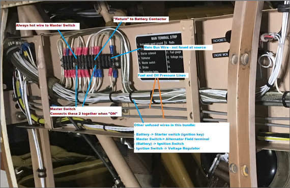
Untangled
So let's see. We've got this bundle of wires, a lot of which are not fused, and one of which is always hot.
The Main Buss wire is the thickest one (10 gauge maybe?) that's not fused between this buss bar and the source (engine compartment).
Oh, did I mention that this buss bar is on the side of the plane near the rear instrument panel (so that 10 gauge run, and the rest of the harness between firewall and the panel is about 30 inches long)?
What else do we see there? Oh! The two little 1/16inch thick aluminum lines carrying.. fuel pressure (and oil pressure).
Shall I say more?
Shall I say that there's a fuel tank in between the front hole (passenger) and the firewall?
That the wires run along between firewall and rear cockpit along that fuel pressure line (to fuel pressure gauge)?
That if one shorts to this very nearby fuel pressure line, it'll burn a hole straight thru it, and then ignite the gas that'll start coming out?
Yep.
Can I fix all of that?
Sure. But rewiring will be much much easier, because I have to touch pretty much everything. Re-running half of individual wires in a bundle is much harder than re-running them all.
So, I made a decision to rewire the plane... Sigh. Looks like I won't be flying for a looooong time.
Oh, and tell you what. Tracing wires on a biplane is dangerous. I ended up twisting my knee and pulling a muscle while trying to get behind the panel so badly that I couldn't walk (or sit) for 2.5 days :(.
Navy carrier pilots regards Air Force pilots:
“Flare to land, squat to pee.”
Up ↑
© Copyright "79FT". All rights reserved. Feel free to cite, but link back to the pages cited.
This website only shows how I did things in my various projects. These pages are for information and personal entertainment only and not to be construed as the only way, or even the perceived correct way of doing things. You are responsible for your own safety and techniques.