[79FT]: Building Things

Alternator: Initial Fit-Up

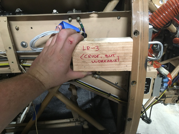
...I almost decided to make new nose baffles


On: Aug 16, 2019
In: [Chickenhouse Charger] Electrical Rebuild
Time logged: 4.8
Tags: 6781G, MA5 Charger, electrical, alternator

So most orders have been placed, and a lot of them have arrived already. (Note to self: need to take pictures of all the stuff).

The first thing to be worked on is the heart - the alternator.

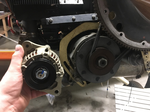
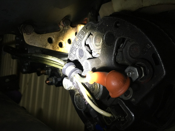
Look at this little beauty!

B&C L-40

B&C L-40

Tiny, light as a feather, and cute as a button! No, sir, this thing has to get attached to the nose!

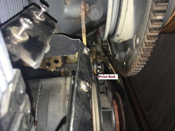
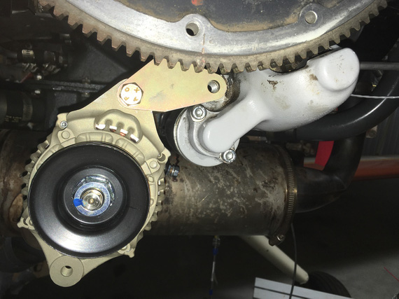
The old one needs to come off. Pivot arm bolt undone. Pivot bold undone.

Wait. The pivot bolt can't get out, because the flywheel gets in the way...

Pivot bolt and interference

Pivot bolt and interference

Hmm.. No, I can't believe Remo pulled the flywheel off of crank just to install the alternator. There must be a better way.

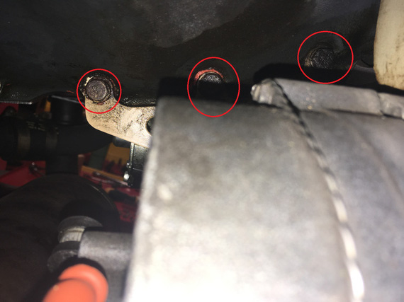
The better way - bracket attach bolts!

The better way - bracket attach bolts!

Aha! This is case mount, and the bracket is attached to the motor case. Let's see... Yep! It came off.

Now, the new bracket... centers nicely!

New bracket

New bracket

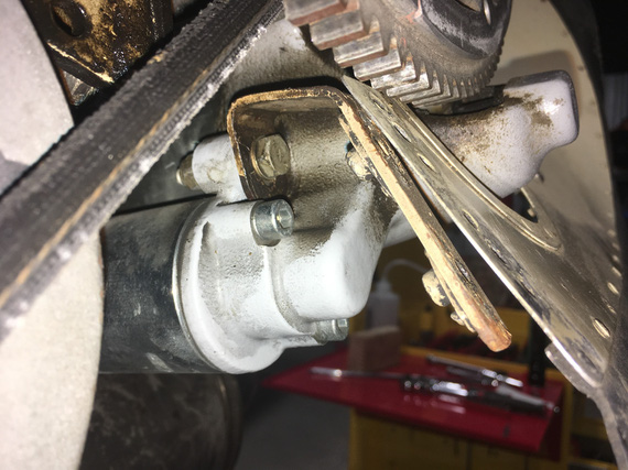
See that ear on the right, that touches the starter boss? That one needs to attach to the starter, to prevent the bracket flexing left and right. It lines up great, but, problem number one (but I knew this one), the old alternator bracket didn't have that. Remo used that hole on the starter boss to hook up the front of the nose "ramp" part of the baffle:

Baffle attach bracket

Baffle attach bracket

No matter. I will just bend up a new one, to account for the thickness of the new bracket's "ear" that will get sandwiched between this baffle attach bracket, and the starter boss. Material already ordered!

Now, let's test fit the belt, and the new pivot arm. The belt, the belt.. oh wait. Yep. The prop needs to come off - but this is a non-event now (and I am not leaving the prop off again - learned that one already). I'm becoming quite good at this prop pulling business....

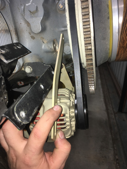
Belt on and prop back on, test-fitting the pivot arm... CRUD!

Pivot arm

Pivot arm

That black bracket to the left of it holds the hose "ramp" portion of the baffle..... and, it won't let the damn pivot arm go in! No way. And no easy modification here - it's interfering, seriously...

Frankly, at that point I went home (this whole note covers quite a few days of work), with thoughts of remaking the front baffle; and spent the evening researching how baffles are done on planes with similar nosebowl... Frankly, I don't like how this front baffle is done on this plane (see Cowling Conundrum), and thought of this as being a good chance to fix it. I moaned about this to my buddy and colleague Dima D (who's helping me here quite a lot with notes and advice)...

But next nite, I thought that maybe I can get away with remaking just the arm... I am absolutely not set up to do complicated sheet metal work at the moment...

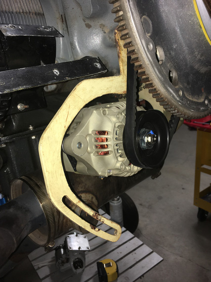
The old alternator had this weird pivot arm that now made way more sense. It "doglegged" around the bracket with which the standard pivot arm interfered:

The old pivot arm

The old pivot arm

Notice how it has this portion that goes down, and then the pivot arm "turns" left to go under the nose baffle ramp attach bracket?

That corner is definitely a large stress riser... but this arm held a much heavier Delco-Remy alternator for almost 40 years... Granted, it's made out of 0.190 steel as opposed to 0.125 steel used in B&C bracket... but I can make a similar one for the new alternator...

We'll see if we can smooth out that corner so that it's arcing better, reducing stress. If I can, I will use 0.125 steel. If I can't, I'll settle with 0.190 - just like the old one. We know this works.

Thanks Dima! You were right. For now. I will redo this nose ramp when I'm redoing the motor, later :).

... and now, to the belt. Let's get this nose ramp back on. It has an opening for the belt to pass thru, and a fairing for the alternator pulley....

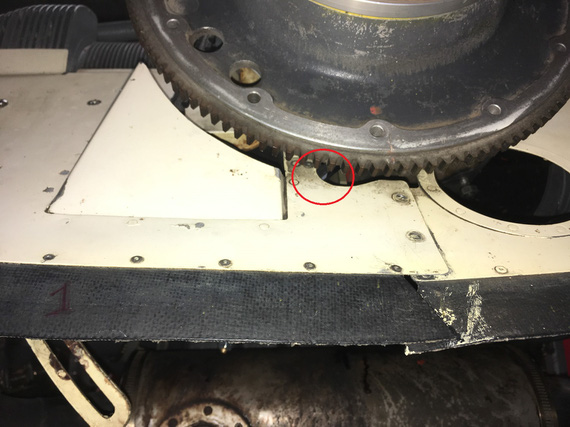
Damn. Yep. That one doesn't fit right, either.

Nose ramp back on

Nose ramp back on

If you look real careful inside the red circle, you can just see the belt there. It will rub on the left edge of that hole. It has to go right, which means the alternator has to go down, which means longer belt.

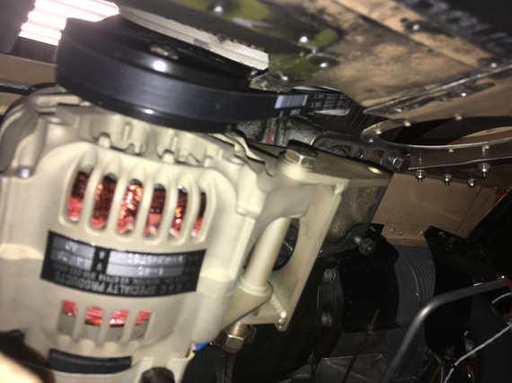
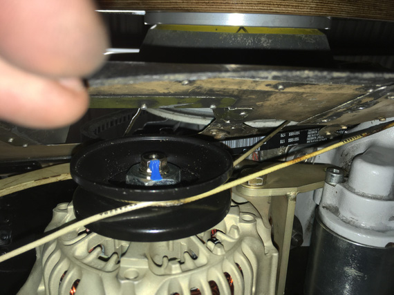
I used a piece of wire to mock this up. Here are a couple of pictures from the back side.

B&C supplied belt - interference

B&C supplied belt - interference

Wire mocking up a longer belt - so that it's centered in the hole

Wire mocking up a longer belt - so that it's centered in the hole

I ordered a couple of longer belts from the same series, to try them out and see how they will work in the end...

So, where are we at?

  • I will need a new, smaller, bracket for the front support of that nose baffle ramp (the bracket will attach to the starter, same place as before)
  • I will need to design and make a new pivot arm - and to learn how to make nice slots with hand tools
  • A different belt

Meanwhile, folks at B&C were extremely helpful and generous with their time, reading my long, ranty, emails, and responding to me with their thoughts. I really appreciated that!


Flying is not dangerous; crashing is dangerous.


Up ↑

Wiring Diagram, v1

...proposed


On: Aug 11, 2019
In: [Chickenhouse Charger] Electrical Rebuild
Time logged: 28.5
Tags: 6781G, MA5 Charger, electrical

So this was quite an effort - not because it was a sophisticated design, but rather because it took quite a bit of time to lay out in a reasonable fashion...

Oh, and also, somewhere in between I had a break for Oshkosh and a work trip :).

I decided to post this in a form of design notes, so that I can go around asking people what they think...

The New Wiring Diagram

I have posted it in PDF over here.

Wire length / drop / load calculations are in the Excel spreadhseet over here.

  • The design is based on Figure Z-11 from AeroElectric Connection by Bob Nuckolls, with the following tweaks:
    • I'm using the B&C LR3C Voltage Regulator, so it's wiring has been incorporated
    • I dropped the Endurance and Main Battery busses
    • I have tweaked the starting switches circuit, main buss feeder, and how ammeter is hooked up - see below for discussion
  • The diagram is laid out to generally clump the components together as they would be on the airplane. It initially might seem convoluted - but it has a certain flow to it matching the locations of components. Start in bottom right corner for battery/starter/alternator circuitry and go counter clockwise - this will effectively take you "thru the airplane" as the components will be laid out; roughly

Review Items and Commentary on Specifics

Starter Circuitry

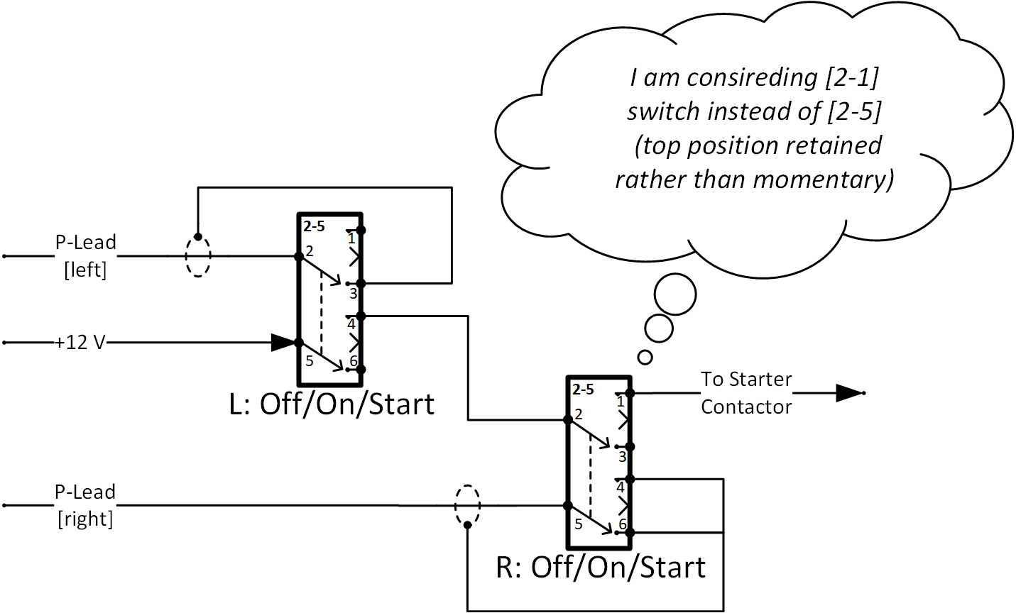
My current take on my Starter and Mags circuitry is this:

Starting and Mags Circuit

Starting and Mags Circuit

This is a deviation from Z-11, with both switches having to be in the momentary up position for starter to engage. I like this better for two reasons:

  • It makes the act of starting the motor more explicit
  • It returns back to correct "running" position automatically

I need to test the ergonomics of pressing up a couple switches together. If I don't like it, another alternative would be to replace the "Right Mag" switch circuitry from -5 to -1: making the top position on it non-momentary (as noted on the diagram). This will reduce the "user-friendliness" but will still keep the explicitness, especially with my using pull-to-unlock switches from Honeywell.

Main Power Distribution

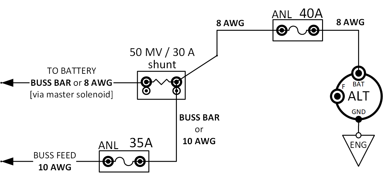
The Charging and Buss circuitry excerpt below:

Power Distribution

Power Distribution

Note that:

Shunt is set up to be in the "battery" lead. I like "battery lead" style ammeters, showing charge current on the 12-o-clock-plus segment, and discharge current on the 12-o-clock-minus segment.

Note that the buss feeder wire is protected by a slow-burn 35A current limiter. In Z-11, that wire is not protected at all. My reasoning for this decision is that this wire is relatively long on my plane (around 4 feet), since fuse block is near the rear cockpit. I wanted to protect it.

One area of concern here is that in the event of alternator short, the Ammeter Shunt will be a part of the alternator circuit that will see a lot of current while the 40A slow burn opens up. My gutfeel says it should be able to handle it, but I am not sure. At any rate, figure Z-11 has the same setup with shunt on the alternator's B-Lead.

Voltage Regulator Sense Wire

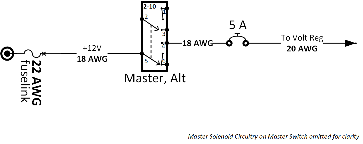
LR3C Voltage Regulator needs a separate "voltage sense" wire that one would normally connect to the main buss. Since the regulator in my case is closer to the firewall than to the buss (fuse) block, I am connecting it to the main battery circuitry (jumper wire between Starter and Master contactors). This is somewhat a shorter run and seems that it will be more logical to measure as close to the battery as possible (especially since I'm saving on wire lengths this way). Seems sensible to me.

The sense wire will be 20 AWG, about 3' long, and connected via 24 AWG fuselink.

Voltage Regulator Field Supply Circuit

The circuit looks like this:

Field Supply Circuit

Field Supply Circuit

I copied the AeroElectric's figure Z-11 wire gauges here. In Z-11, everything upstream of Breaker is 18 AWG, and everything downstream is 20 AWG, but it's not explained why.

Is this driven by a requirement to ensure that fuselink survives the short in the circuit in case of crowbaring, and the breaker pops first, w/o endangering the fuselink much (18 AWG allows for 22 AWG fuselink instead of 24 AWG)?

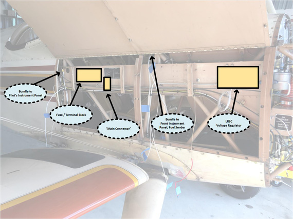
Components Location and Main Connector

Here's a relative diagram of components location, that is necessary for explaining what Main Connector is. Click it for larger version.

Key component locations

Key component locations

Note that logically, the way one would wire this airplane would be to pre-wire switches and other items that go into the pilot's (back) instrument panel with long pigtails, then install the switches, and tie down wiring behind the panel. Then, the pigtails can be connected to fuse block and loads.

Some of the load wires already exist (lighting for example), and they will have to be spliced to wires coming from switches.

I have decided instead to locate a kind of "Main Connector" right there near the Fuse Block. A wire comes off of the Fuse Block, goes to the switch on the panel, then switched power is returned to the "Main Connector". Load is on the other side of Main Connector.

This serves a couple purposes:

  • Create a logical "access point" into the main wire bundle, for reading labels, tracing wires later, and such
  • Simplify installation process
  • Connect to existing load wires that are not being replaced

For now, I am thinking about using Molex 0.093 pins in two housings (I have 13 circuits total to connect via this thing, and want to have room for further expansion). I would love suggestions here. One of the requirements is that it should be easily workable with a multimeter for tracing / testing purposes (I technically could've used D-Sub here , but am not due to this precise reason).

Separate Switch for Turn and Bank

Yes, it's weird to have that. The original electrical had it. I guess, the logic was to be able to shed half an amp of unnecessary load in the event of alternator failure, or it was just done for no good reason.

I'm keeping it :).

Front Panel Tach

It's a Westach gauge that feeds off of a magneto P-Lead. No separate power going to it.

Westach asks for a 1/4 A inline fuse. But why? Seems unnecessary (we don't need to fuse P-Leads).

Wire going to this tach in my opinion need to be shielded P-Lead wire. Not sure if I'm correct here.

I need to tie into one of the P-Leads. I have three options:

At magneto: I will effectively have two P-Leads coming off of one of them. I have Bendix mags, and connectors on those might make the whole hookup look ugly. Adds extra wire.

At mag switch in the rear panel: just adds extra ~4 feet of wire for no reason.

Y-Split the P-lead as it goes along the fuselage: this seems the most optimal wire-management wise, but I am not sure if splicing into a P-lead is kosher. I don't see any good reasons why that would be bad, but I don't know everything. This will likely be a soldered splice unless I find or someone suggests something better. This is my solution of choice at the moment.

Panel Lighting

I am on the fence on this one. On one hand, I can add a nice LED strip light and dimmer to light the panel up.

On the other hand, this is extra weight, and "this is a biplane! you won't fly it at night!" vs. "well what if you find yourself out late" keeps nagging me. Note: I do not have a landing light (though in a biplane... that's somewhat a non-necessity ;) ).

I am leaning towards doing it, because doing it now will be easy, and I will have the option to see my gauges at night, even if that Dark and Stormy Night will be a result of bad planning rather than an intentional thing.

10 AWG Feeder for Radios

Radio stack was wired via the "Radio Master" switch prior. I was initially going to run separate power feeds to each of the things in the radio stack, but to get to it, I'll need to pull the wings off (yeah...). It's in between pilot's legs attached to the bottom of the cockpit.

So, the feeder is staying. The stack has been wired by previous owner recently, and isn't wired badly - with individual fuses for each radio, and a 10 AWG feeder to it and ground "return" from it.

I'm just putting this "hose" on a 30A fuse, which is more than enough to protect the wire and support all the loads from that stack.

Strobe and Nav on the Same Circuit

I am replacing (TailNav, WingNav) + (old heavy strobe on belly) with SkyBeacon and SkySensor on wingtips and nav/strobe on the tail, but I don't have enough wiring in the fuselage and wings to have a separate circuit for strobes. I do not plan to fly IFR (biplane!) so "strobes in the clouds" is not really an issue. When I will have the rag off the airplane, I will add a separate switching circuit for just the strobes.


Flying is the perfect vocation for a man who wants to feel like a boy, but not for one who still is.


Up ↑

Electrical Disassembly

...fun with wires


On: Jul 01, 2019
In: [Chickenhouse Charger] Electrical Rebuild
Time logged: 13.1
Tags: 6781G, MA5 Charger, electrical, soldering

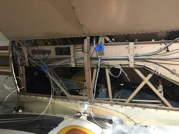
Well, all the electrical on the Charger is disassembled now. I logged about 24 hours doing it.

Firewall wire harness, looking into the side conduit

Firewall wire harness, looking into the side conduit

I have started with wires on the terminal block and in the side channel, and was moving back and forth between various locations - get bored in one, move on to the next.

The disassembly has begun!

The disassembly has begun!

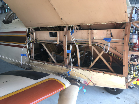
In the side conduit, going on the right side of the plane to the back cockpit, I was slowly removing the wires, and the oil and fuel pressure lines.

Had to be careful to mark the wires I wanted to keep - all the wires going to the lights, and some instruments in the front and back.

Wire by wire...

Wire by wire...

I would cut them off, and pull them out one by one.

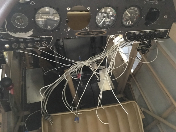
Behind the panel is a rat's nest!

Behind the panel is a rat's nest!

I pulled the mechanical tach and it's cable, and the oil temp and pressure and fuel pressure gauge.

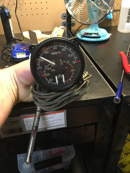
By the way, the oil temp gauge was unpowered! And still ran on a thermocouple - but it's huge, to generate enough power to move the needle.

Old school!

Old school!

Heck, I'm keeping it as my IHT Gauge!!! (Internal Hangar Temperature, that is). It just looks too cool.

Eventually, all the wires were gone from there, aside from the ones I'm keeping; and the ones I'm keeping got temporarily marked.

All done!

All done!

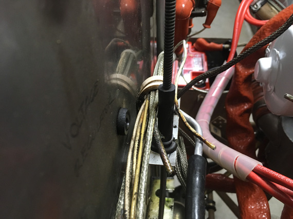
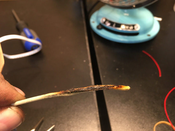
By the way, I found a burnt wire! Was one of the unfused wires going to the voltage regulator.

Burnt wire - can you see it?

Burnt wire - can you see it?

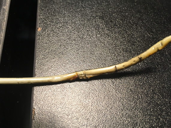
I cut off the burnt chunk.

Front

Front

Back

Back

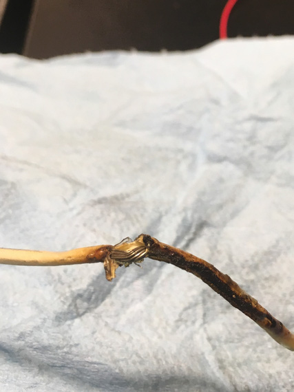
See those little "boil bubbles" on the back side? Insulation was super brittle, and just a minor twist cracked it open.

Cracked

Cracked

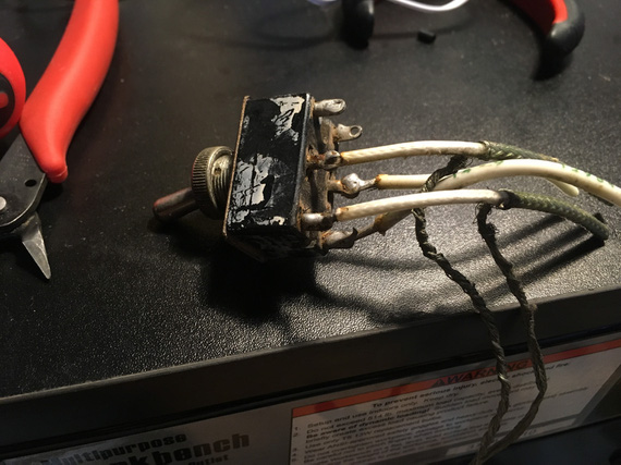
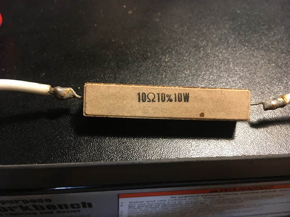
Meanwhile, behind the panel were a couple of soldered things - with wires unsupported. One of them was the master switch, the other one was this weird resistor in the voltage regulator circuit where the low voltage alarm light was supposed to be.. go figure.

But look at the solder joints:

Master Switch

Master Switch

Resistor

Resistor

Notice, they were not done very carefully (especially the ones on the Master Switch). Flux was not cleaned. But! The joints look, and are, solid. They are almost 40 years old.

I think I am officially now in the "no soldering on airplanes is an old wife's tale" camp.

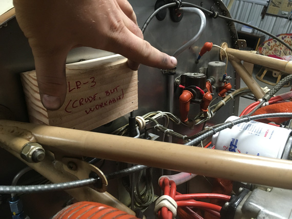
At some point, I decided to take a break, and try on the new Voltage Regulator I'm planning on installing.

....it's not up to scale, and I did not have the time to paint it...

....it's not up to scale, and I did not have the time to paint it...

FWF location

FWF location

Side Conduit location

Side Conduit location

I'm thinking I'm gonna mount it in that conduit on the side. It'll stay cooler, and generally be tidier. I'll use the space occupied by the old voltage regulator for my current limiters and the ammeter shunt, though still need to think a bit more about placement. Maybe those will go somewhere else, too.

By the way, the old voltage regulator in all it's glory:

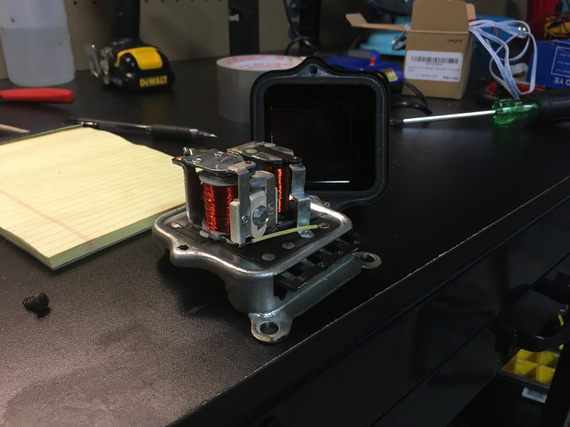
A Mechanical Switching Voltage Regulator

A Mechanical Switching Voltage Regulator

I also completely removed the strobe - I'll be replacing nav lights with SkyBeacon/SkySensor; which will cover my blinking needs.

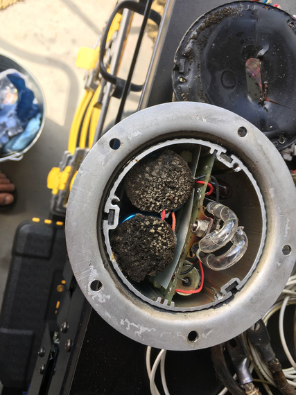
Wanna see a couple old electrolytic caps? The strobe power supply still worked, by the way!

The Strobe power supply and bulb

The Strobe power supply and bulb

I have disassembled the charging and starting circuits completely, too. Since I'm redoing everything anyway, adding better wires, and new terminals would not add too much expense, and be good for the system. I also want to modify how battery is grounded.

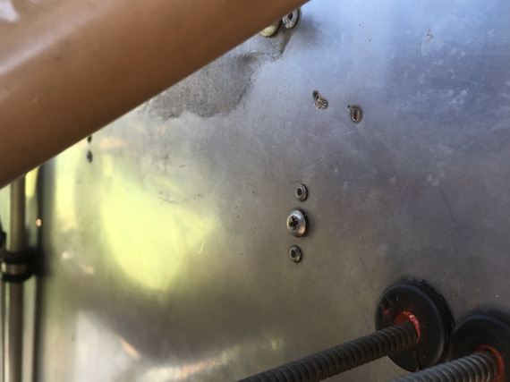
Found this next to the Master Contactor

Accidental welding on firewall

Accidental welding on firewall

Do you see it? Two spots, above the screw? Someone didn't disconnect the cable when working on her! :). (And, no, that wasn't me)

And finally, here's how almost the entirety of electrical system looks like.

Most of the electrical of a biplane

Most of the electrical of a biplane

Some swithces, some fuses, some wire, and that's it!


In thrust I trust.


Up ↑

Wire Markings, Fuselinks, Load Measurements, and Turn-and-Slip

tested fuselinks, measured loads, removed and diagnosed turn-and-slip indicator


On: Jun 18, 2019
In: [Chickenhouse Charger] Electrical Rebuild
Time logged: 6.5
Tags: 6781G, MA5 Charger, electrical, experiments, research, instruments, soldering

Finally, doing some actual work on the airplane, and having fun! And I decided to start logging time.. because, why not!

Wire Marking

I like marked wires. I used to be a networking guy, and I was very meticulous about marking every single wire in my cabinets, so that I knew exactly what was plugged in where.

It took a bit of upfront time, but saved a bunch of it later on.

So naturally, I was planning to do the same on the Charger, and, more importantly, make it look professional.

Thanks to living in this day and age, that is simple. No, I'm not gonna pay someone to laser etch my wires - that's a cop out :). It's like paying someone to paint your plane.

Instead, I have researched and found a perfect label maker - Brady BMP21 (not including a link here because it will probably go dead after some time... just search for it). This thing has 3:1 heatshrink tube cartridges.

The proverbial coupon

The proverbial coupon

Prior to shrinking

Prior to shrinking

Shrunk!

Shrunk!

Load Measurements

Prior to ripping the old wiring out, I wanted to take some real life load measurements with various things turned on, so that I don't get any nasty surprises.

But this plane has no ammeter... damn. I searched around, and found this little doodad:

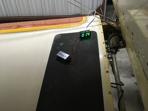
Hall Effect ammeter

Hall Effect ammeter

Very nice. It basically measures current on the wire passing thru this big white ring using Hall effect. Very cool! No need to splice into the battery leads and install a temp shunt.

So, I rigged it up and took some numbers.

Rigged up

Rigged up

  • Master On: 1.5 amps
    • Includes: Master Solenoid, and a couple of gauges
  • Fuel Pump: 0.2 amps
  • "Radios" switch (turns on engine monitor, and power to radios: turning backlighting on them): 0.8 amps
  • I-Com Radio, Transmit: 2.6 amps
  • Intercom: 0.1 amps
  • Transponder: 1.1 amps
  • Smoke Oil pump: 2.2 - 2.6 amps (high on startup)

So couple interesting things here. I think the x-der number is too low, but it wasn't being interrogated, and I can't make it be interrogated without flying the plane or using a transponder tester which I don't have. Also, Master On is too high seemingly... Will need to double check later and isolate things (master solenoid, hobbs, voltmeter, voltage regulator, fuel gauge) if I care enough - I don't think I do. Also, fuel pump is too low seemingly. Need to double-check the spec.

And then, I could not turn on the Turn-Slip Indicator...

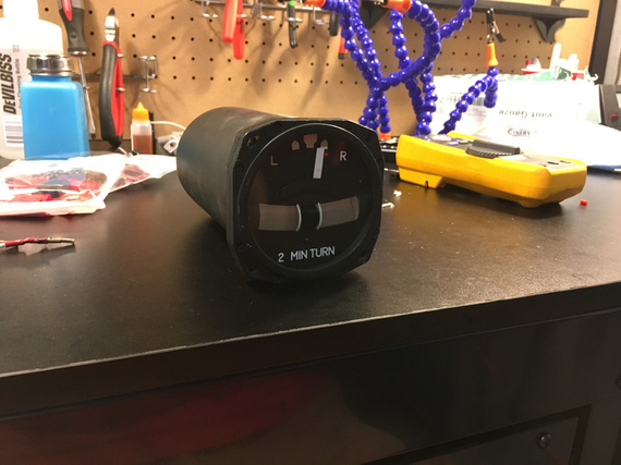
Turn-Slip Indicator

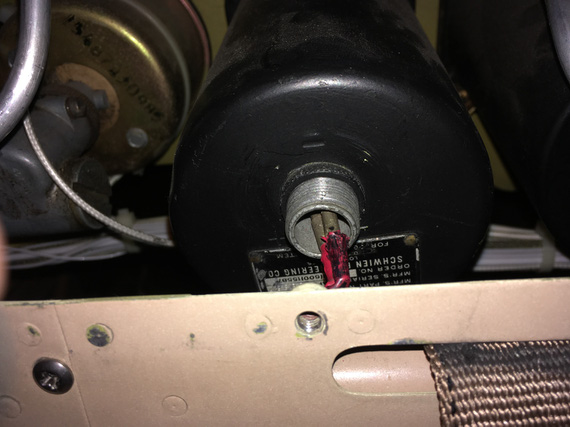
Sad, sad indicator... see, it's long. And it's wire connector is sticking out. And it's right behind the front seat's headrest, and there's just not enough room for it, and the connector.

So whomever put it in... did this:

Sad, sad wiring

Sad, sad wiring

It's hard to see; but basically, those wires are bent "down" at a very sharp 90 degrees angle. Notice how he just used pins without the actual connector. The distance between them is tiny! I am surprised they haven't shorted over all these years. I really am.

Initially, I thought the gauge didn't turn on because that wiring was all bust up, so to test it, I decided to pull it out.

On the bench

On the bench

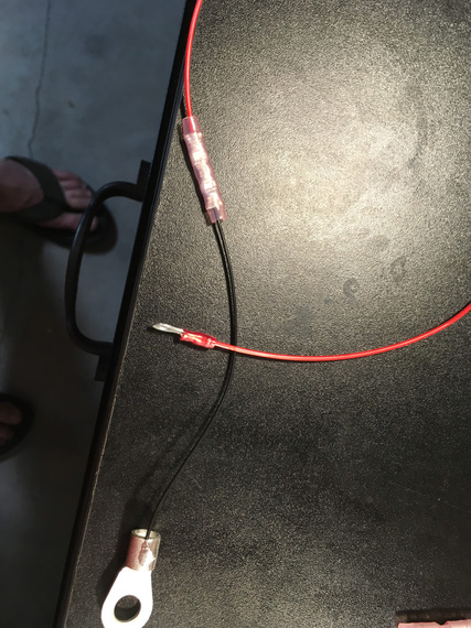
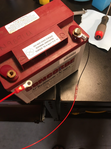
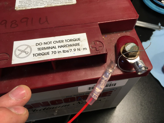
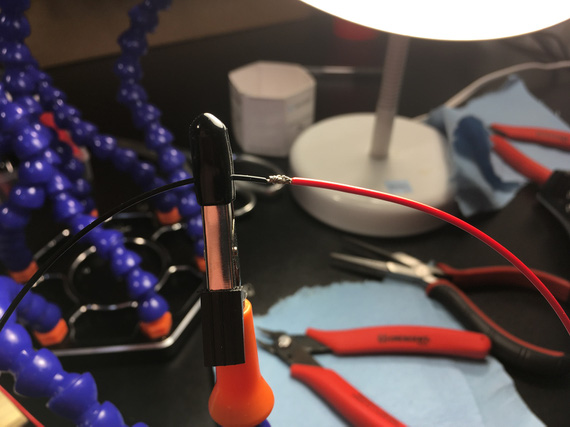
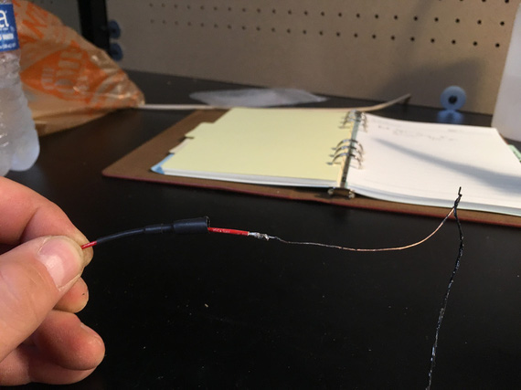
I cut off the wires with those pins on them to hook it up to my testing battery... hmm.. but I needed some leads! Well, I was gonna make a bunch of various test leads - so this is as good a time as any! Man, I love soldering...

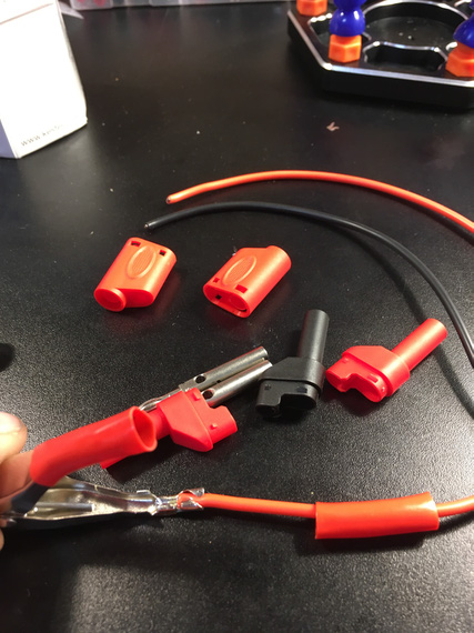
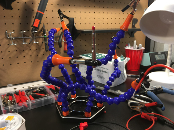
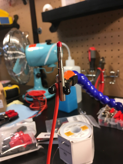
I long decided to make a bunch of leads with "passthru" banana plugs on one end, and something (a crocodile clamp, a battery clamp, a ring terminal) on the other. This way, I could mix and match, and plug them into my multimeter; daisy chain, and have multiples depending on what and how I needed to hook up. I had all the bits (clamps, crocodiles, banana plugs), and even got a roll of very nice super flexible silicone coated probe wire.

Components, and the battery clamp crimped on

Components, and the battery clamp crimped on

Release the Soldering Kraken!

Release the Soldering Kraken!

The banana plug pin

The banana plug pin

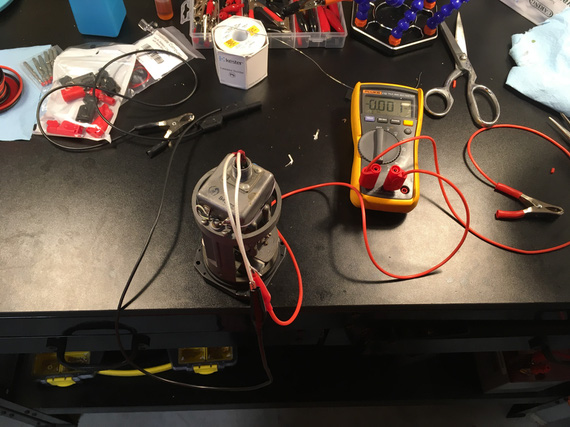
All hooked up

All hooked up

The gyro in the gauge didn't start. Damn.

But I had resistance between + and -. And I had voltage! Hmmm..

Second time I hooked it up, I saw a bit of a spark when I put the positive clamp to the battery, and heard something.

I spun the gyro with my finger.... it spun up!

Well, well. So that gyro "froze" in a bit... Yep, it was hard to turn over with a finger - no doubt a small motor in there had a hard time!

I probably "cleared it up" a bit when turning it over with my fingers - but that won't last long... damn.

Are we looking at the overhaul for this thing too now? Sigh.... Maybe I can find parts to do that myself, but not so sure about that.... It's not common for owners to overhaul their instruments - they're precision clockwork, after all...

Oh well.

And I will have to figure out how to solve that wiring problem with no space to hook up the right type connector. I am thinking along the lines of maybe routing a wire from inside of the gauge down thru a hole I'd drill, a grommet it it, and covering the whole business with with some sealant or something, so that the dust doesn't get in. we'll see. Need to ponder this a bit more.

PS

... and here's what happens to airplanes that aren't flown enough...

Dinner for someone...

Dinner for someone...


Standard checklist philosophy requires that pilots read to each other the actions they perform every flight, and recite from memory those they need every three years.


Up ↑

Hangar Redo

cleaning up!


On: Jun 17, 2019
In: [Dream Shop] Georgetown Annex
Tags: shop, hangar, tools

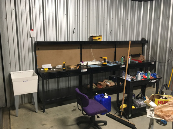
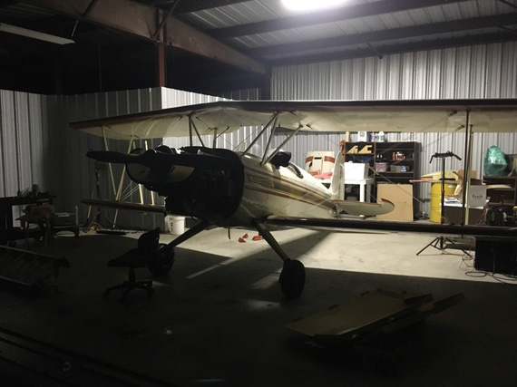
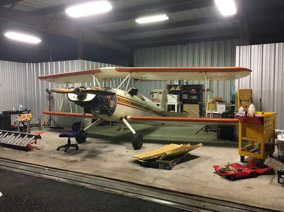
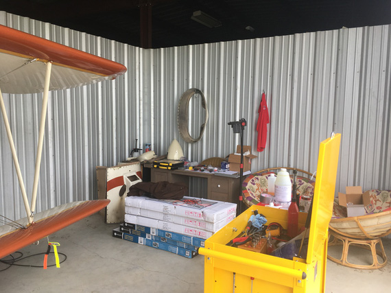
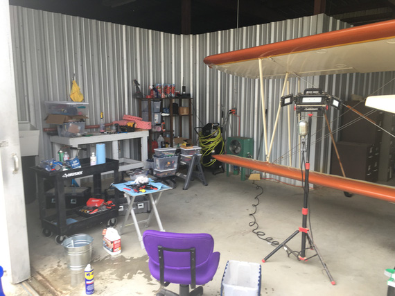
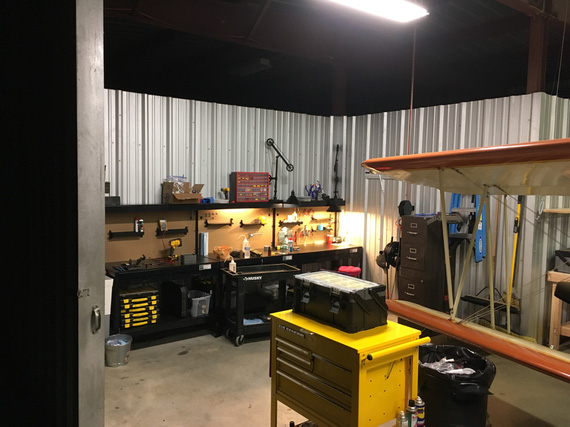
Well, since it seems now that my Hangar will become my shop for a while with me doing the electrical rebuild on the Charger, I decided to set myself up in it. I am still rebuilding the main shop at the house (reminder: need to write up a couple notes on that), so the only place I have to work on the plane is in the hangar - and frankly, I probably wouldn't have dragged the whole thing over to the house anyway just for an electrical rebuild... though it is getting hot, and being in a tin can of a hangar when it's 100 degrees outside is not.. pleasant, shall we say.

At any rate, the Hangar is now to be officially known as The Dream Shop, Georgetown Annex!

Not much to tell - but much to show here.

Easy Route

I didn't have anything in the hangar besides a couple of old bookshelves, a couple of small tables, a few filing cabinets I have inherited from my good friend Pete, and a cart. Not very nicely set up for working on airplanes, and everything was overflowing with parts, tools, and hardware even after just a bit of disassembly I have done for the annual.

I needed a lot of shelf space, and a lot of bench space.

I decided to take an easy route this time, and instead of building everything, just bought a bunch of shelves at Costco, and benches and a tool cart at ... Harbor Freight. Yep, I know. Throw a rotten egg in my face next time you see me.

The First Shelf

The First Shelf

The Light

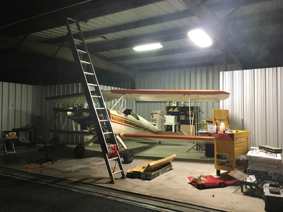
I work evenings a lot, and the only light source there was there was a four T8 tube fixture in the back of the hangar. But the most interesting stuff is on the front of it (engine, yep :) ). So I added some lights around the front.

Lights

Lights

The Benches

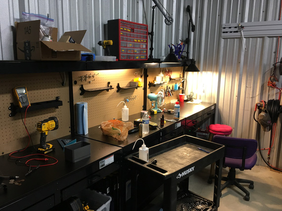
Next, came the benches from Harbor Freight. Don't buy them. They're built like crap, and, frankly, I think I could've built better ones out of 2x4s in about the same amount of time it took me to put these together... But hey, I already bought them, and disassembling the first one (I got three total) rather than putting the other two together... I didn't want to...

Benches

Benches

You might notice the pegboard at the back "wall" of those benches. Well, they attach it every about 12 inches around the perimeter with machine screws and nuts. Guess what happened to the first pegboard after a humidity cycled high, and then low? Yep; it all warped!

Ended up resorting to straightening it out with shelves that acted as "stiffeners", and putting the warped pegboard bench as far away from the "main" bench as possible).

On the other two I actually made the pegboard "floating" - re-drilled the mounting holes to be large, and used large washers and just enough small washers underneath to MacGyver me a "bushing". That worked, and the other two benches' pegboard is straight after quite a few large humidity changes now.

And then, the sink.

The Sink

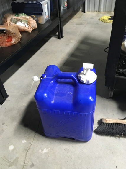
I long had a large 7 gallon jug with a tap. When I was doing a lot of work, I'd drag it out of the hangar, put it on a small folding table, and use it to wash my hands. Very nice to be able to do that when your hands are covered in oil and crud, and you need to climb into the airplane or grab something generally clean. I also like clean hands when doing detail work like soldering, painting, etc.

The Jug

The Jug

But dragging out a 7 gallon jug every time I got into the hangar got very old very fast, and I ended up typically resorting to rags and not so clean hands, or "washing" them with mineral spirits... ugh.

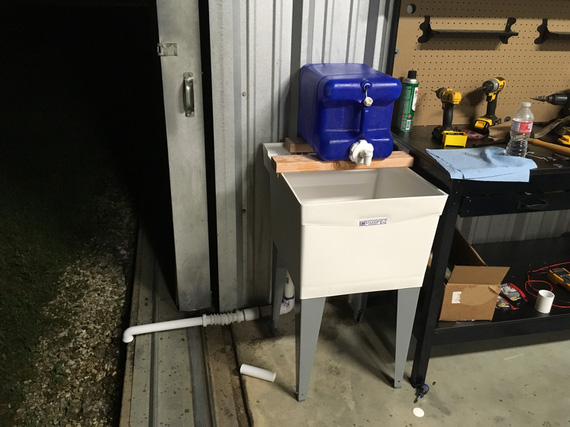
But hey, we're cleaning up! So I decided to put in...

The Sink!

The Sink!

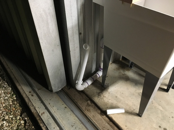
But a sink needs a drain!

No problem.

The Drain.

The Drain.

This came out very nice, and I love that I can now just wash my hands whenever, no jug dragging required.

The best part? The hangar door slides, so I can have it closed and then slide it a bit past it's "closed" position, so that there's a gap between the hangar divider wall and the outside for the drain to be put out.

But how do I close the door?

Retractable!

Retractable!

Do I need a Complex endorsement to operate in my hangar now? ;)

The Wiring

Before you wire your plane, wire your hangar, says a proverb. Or something like that.

Well, my hangar floods. And it's not my hangar, so I can't quite make holes in the walls and run wiring and conduit. And I only have one outlet. Yep.

So it was all to be a bunch of extension cords, making sure that all connections are suspended a few inches above the floor, hooked to something (previous tenant of my hangar had some holes in the walls drilled, so I reused his, or hooked them up to legs of whatever was there, etc).

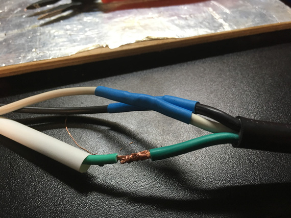
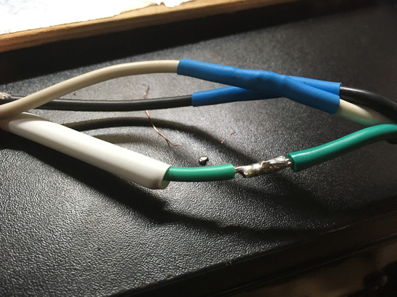
I ended up making a bunch of splices on extension cords. Hey, I love soldering!

Almost a splice

Almost a splice

And now, with liquid metal!

And now, with liquid metal!

Air and Shelves

I had a compressor. I moved it to the back corner of the hanger, and hooked up a reel in the front, so that I can have my hoses neat... Not much more.

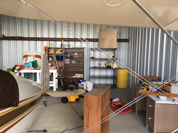
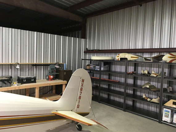
The back wall of the hangar got lined with the big shelves, too... Mostly, to stack the parts I take off the plane and need to keep off.

The first one up is there on the right, near the yellow barrel.

The First Shelf

The First Shelf

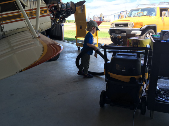
Some child labor might have been involved in cleaning this hangar

Some child labor might have been involved in cleaning this hangar

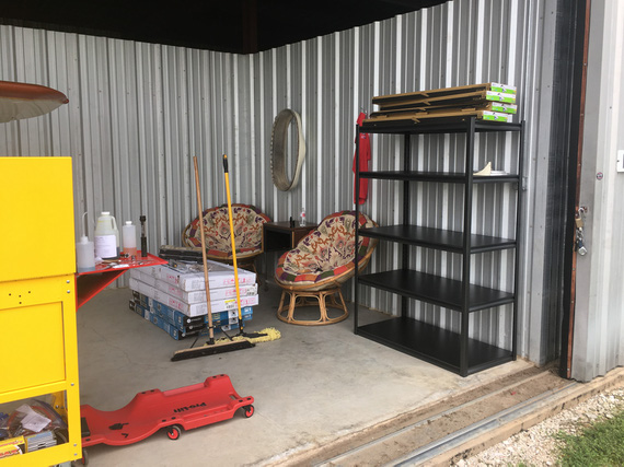
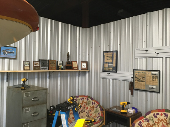
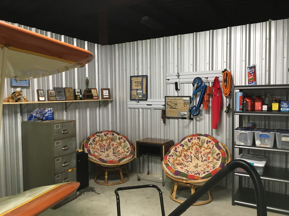
The Shrine

... and since the Charger is a Grand Champion, I needed a shrine in the "mancave corner" of the hangar. Every hangar must have a corner with a couch, a fridge and what-not, to relax and ponder and procrastinate. And that's where all the artifacts need to go.

The Shrine

The Shrine

And I didn't drill a single hole! All those rails and shelf are re-using the screws that are holding the hangar walls together :).

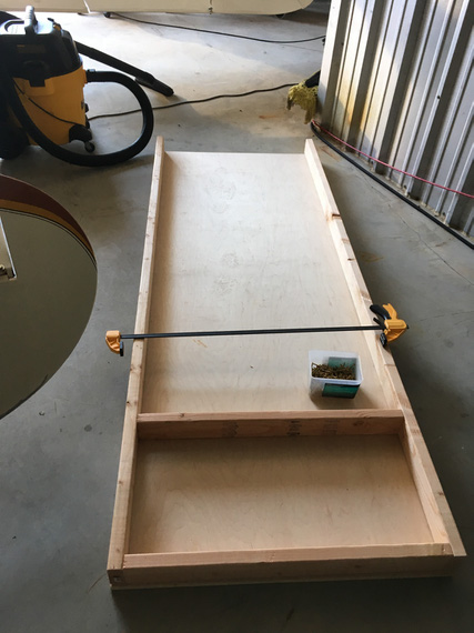
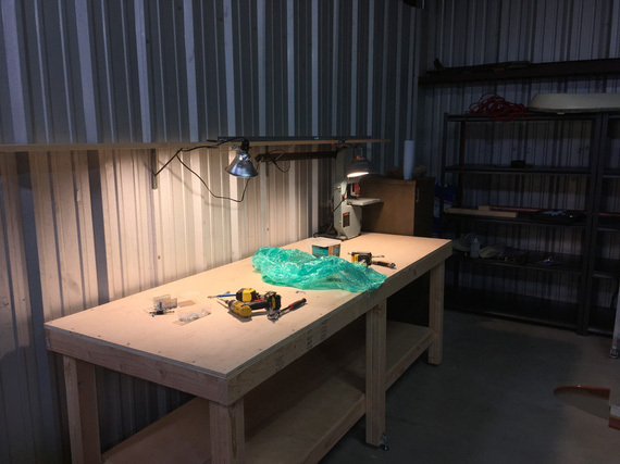
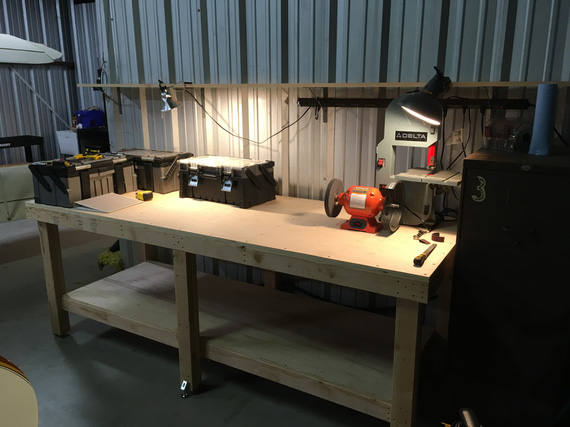
The Bench

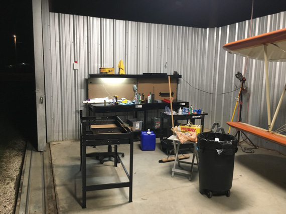
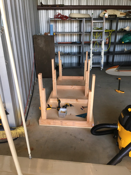
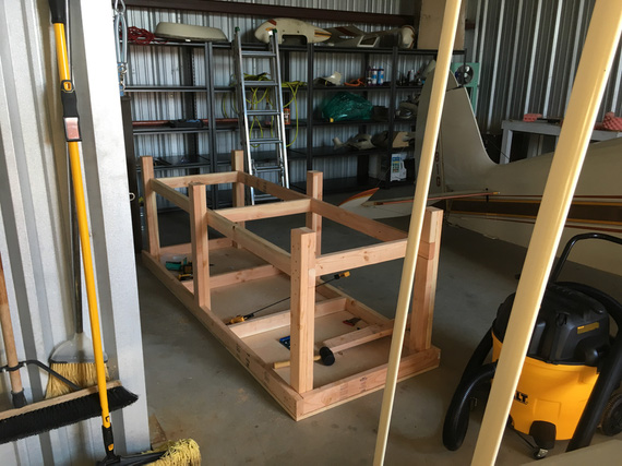
I needed at least one good bench for grinders, bandsaw, and aluminum work; and there was a perfect spot for it. Didn't have my wood tools though, so had to use 2x4s straight out of the store... Normally, I mill them down :).

The top and the frame to be

The top and the frame to be

Legs

Legs

All together...

All together...

... and then, you flip it, add the bottom shelf, attach the leg stands, and voila:

The bench

The bench

Even though it's not very flat, it's perfectly fine for anything but being a reference flat surface for assemblies...

Set up

Set up

The End

Well, and I guess, that was it. I spent a few more days and evenings cleaning up, and putting everything in place. And I guess, we're due for some "before" and "after" pics :).

Lighting: before

Lighting: before

Lighting: after

Lighting: after

The mancave: before

The mancave: before

The mancave: after

The mancave: after

The back: before

The back: before

The back: after

The back: after

The main work area: before

The main work area: before

The main work area: after

The main work area: after

Benches' closeup

Benches' closeup

So, there. Took me a month with the breaks for fixing HVAC wiring on a Subaru (funny how that happened in anticipation for rewiring the plane, eh? and I really started to dig Molex connectors doing the fix - but we'll talk about Molex when the time comes), and a bunch of other stuff.

But hey, I can work on things comfortably now. And, wash my hands whenever I want!


I’m from the FAA, and I’m here to help.


Up ↑

Race for the Engine

...or was it pickles?


On: May 17, 2019
In: [Chickenhouse Charger] 2019 Annual
Tags: 6781G, MA5 Charger, Annual, engine, Rotec TBI, prop

So after having discovered the electrical mess, I realized that she's gonna be sitting for a while.

Which meant...

Pickle time! Damn, this pickling thing is becoming a thing, excuse my tautologies...

I had to put her together enough to be able to run the engine to circulate and warm up pickling oil.

And she was apart. With intakes off, TBI almost off, no oil, and such.

Fuel / Intakes

So first, it was to be intakes.
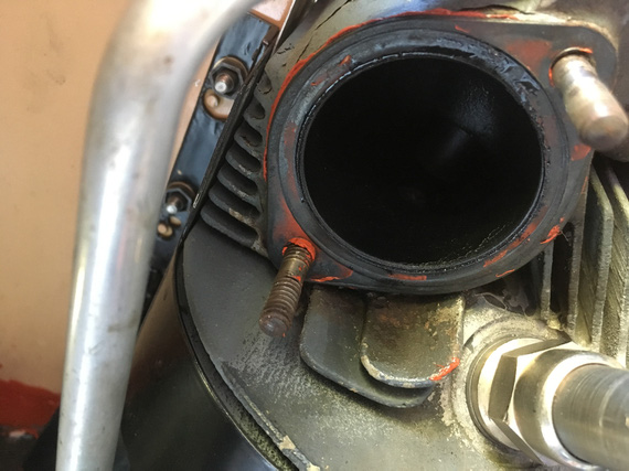
RTV where there should be none

RTV where there should be none

Somebody put RTV to "seal" the intake gasket. Oh well.

Did you know that those 1 1/2 inch rubber hoses that go on intake tubes are much easier with very thin coat of oil?
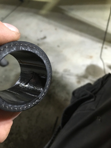
Oiling the hoses

Oiling the hoses

And then, it was the TBI.

Recall that when I was putting her apart, I found pipe dope on the TBI inlet port?

Let me explain.

Fuel goes into gascolator. Then it branches: one branch goes to the engine driven pump, the other goes to the electric pump. Then, they go to the regulator on the TBI. Then, a couple of 90 degree fittings feed it into the TBI's inlet port, which has the "last chance" screen in it.

That's the port here, right above the airflow straightener:
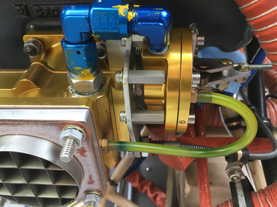
TBI from the down low

TBI from the down low

See that white gunk? That's Teflon dope. "Aircraft grade"; whatever.

Here's the problem.
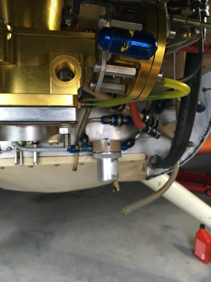
TBI inlet hole

TBI inlet hole

Fuel has to go there, into that inlet hole. That's what the screen fitting screws into. Right past that, inside the TBI itself, there's a turn, another turn, and a spray bar that sprays gas into the intake, injection-style, thru a tube with a bunch of tiny holes. That's why there are screens in the fuel system: to prevent gunk from clogging up those tiny holes.

So now, what happens when you take a male fitting out of a female threaded hole, and the fitting was doped? Some of that stuff ends up on the female portion. Next time the fitting is put in, dope remnants will be pushed in past the engaged threads, and possibly clog up the works.

Not. Good. At. All.

That's why there is the copper crush gasket behind that screen fitting - to seal it to the TBI body w/o requiring anything extra. You can kinda see that gasket all smudged around with that dope on the first picture.

So I had to deal with it.. Clean it out somehow.

It was crumbly, but sticky enough to not want to come out.

I tried every solvent on hand. Nope.

I tried carefully scraping it out with a dental probe. Yeah, kinda worked, but I wasn't satisfied.

I tried every solvent in my buddy Dick's hangar. Nope.

In desperation, I drove to the local Home.. strike that, Aerospace, Depot, thinking about picking up every kind of solvent they had and I didn't.

And then, I remembered this:
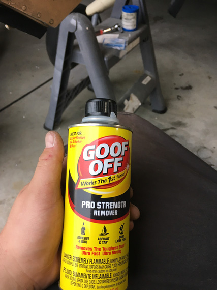
Goof-OFF!

Goof-OFF!

I don't know what kind of concoction that is; but it worked! The hole was clean. Next time was a couple days after, and when I got back to the hangar, I discovered that it has turned into a lake :(
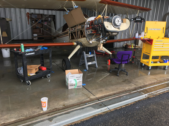
Lake in my hangar

Lake in my hangar

Grading's all screwed up around our hangars, and when we get lots and lots of rain, they flood. Not too much though, luckily. This was the second time in the past few weeks - first time, I had my tools scattered around the floor. This time, I was smarter...

Anyway, back to the TBI. The rest of it went together quite nicely. I discovered that there was TorqueSeal put on the idle mixture screw.

Why? No idea. That screw is spring loaded. Should stay put.
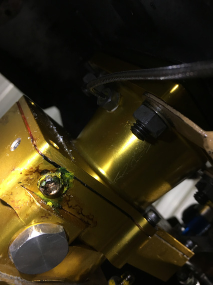
Torque Seal where there should be none

Torque Seal where there should be none

I wanted to flush the lines and then the TBI to make absolutely sure none of that dope went it. The best way to do that would be with the electrical pump; but I'm a one man show.... and the switch for it is 5 feet away from the firewall.

So, I had to rig me up a little doodad.
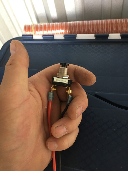
The simple click switch
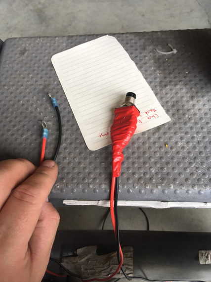
The simple click switch

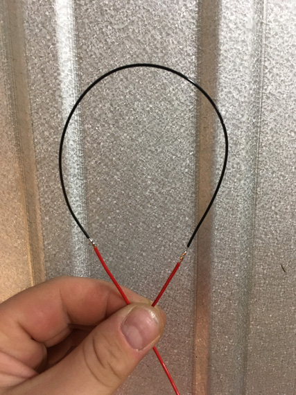
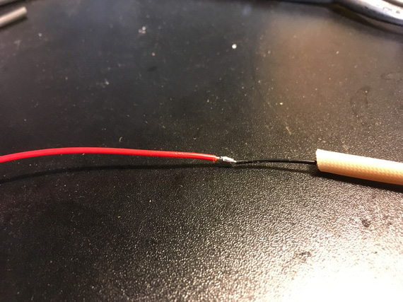
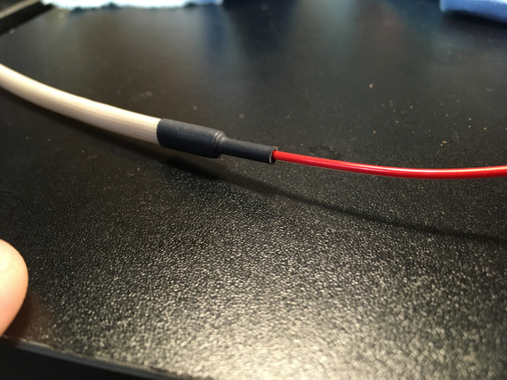
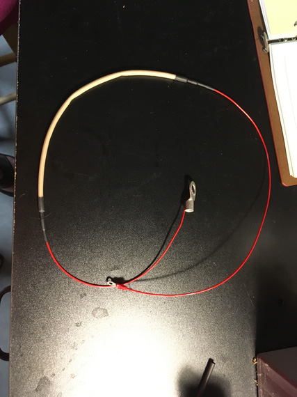
.. with ring terminals

.. with ring terminals

The ring terminals were hooked up to the Master Solenoid in such a way that when the button was clicked on, the Solenoid would close.

The pump was turned on.

This way, I could click my button, Master Solenoid would close, and the pump would start running. Neat-o! I'll need it later, too.
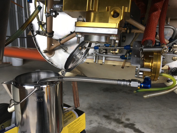
Flushing - braided hose provides nice bond to the airframe

Flushing - braided hose provides nice bond to the airframe

The Pickling

I borescoped the engine (looked alright - I'll post a report about this later, maybe...); and it was time to fill'er up with oil.

Pickling oil was mixed up next, and into the engine it went.
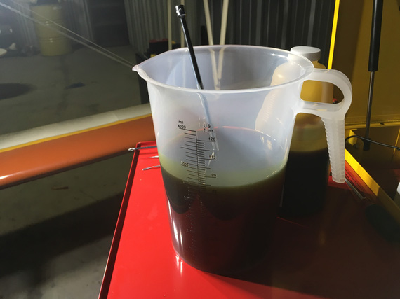
A pitcher of pickling oil
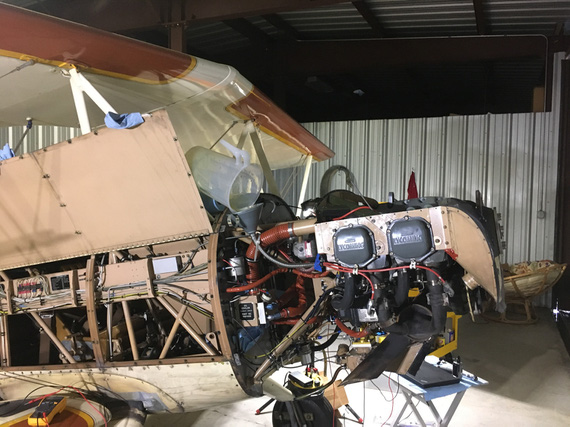
A pitcher of pickling oil

A recipe for a mess...

A recipe for a mess...

After filling the sump up, it was time to check for oil pressure. Lycoming tells you in SB1241C to pre-oil your engine by cranking with the starter in 10-30 second bursts until oil pressure comes up to 20 PSI.

Well, oil pressure gauge on the Charger is finicky, so I wanted it to at least move.

Oh wait. She has an ignition/start switch. No way I can use that to crank and not have a hot mag w/o messing with P-Leads.

Crap.

Also, I might want to crank from around the firewall (the prop was still off).

But I had my pushbutton doodad!

So I rigged it up to the starter solenoid this time.

Of course I misunderstood the way the starter solenoid was wired.

It had two terminals.

I thought one of them was ground; with the wire going to the firewall. The other then was supposed to be positive.

That didn't work.

I measured it - between those terminals - nothing. "Dead starter solenoid", I though. Crap! It was 8pm. Auto parts stores were closing soon.

I rushed to a nearby O'Reilly. Picked up a starter solenoid. Went back.

Measured it too. NOTHING? How come? Something was amiss.

Only then I started suspecting that something was off. That other terminal on the original starter solenoid I was hooking my positive wire to was all corroded and looked like it never had a nut.

OH! The way it's supposed to be wired is that positive goes to the same terminal where that wire I thought to have been ground was. It wasn't a ground wire - it was a diode. And the ground was off of the case of the solenoid.

Okay.

So, we're cranking now.

30 seconds. No pressure. 30 more. No pressure. Crap!

I unhooked the oil pressure sending hose (the one that hooks up to the line that goes to the gauge).

Crank. No oil. A couple bubbles is all I got.

CRAP!

The oil pump de-primed itself?

Kinda makes sense I guess? The plane was sitting for way too long :(

So, I took off the oil cooler return line. Dumped another quart of oil in there.

I had this hose fitting that goes on top of an oil bottle that was very neatly set up to mate with the engine oil hose's flare: so I could squeeze the bottle and push the oil in.

After the whole quart, I re-hooked the line back onto the oil cooler, and tried again.

Success! Now, I saw oil coming out of the oil pressure sending hose.

Hooked it up to the gauge line, and saw the gauge move, finally. Good.

Damn, with all that cranking I ran out my old battery I had put in there.

Now, have to flip the battery (to put in the good one - the flying one - I always use my old battery from the Cheetah when I mess with electrical, not to abuse the actual "production" battery).

Now, the top spark plugs go back in, the ignition wires get hooked up.

Prop time!

Bolt one - start it in. Bolt two. Bolt three.

Bolt 4. Doesn't go in? Not even a chance? What the hell?

I pulled the prop back off and laid it down. Put the front crush plate on top (that one positions the bolts).

No matter what I did, there'd be at least 3 out of 6 bolts that won't go in. This time, it was a few dry days, and I guess the prop moved enough to have the "top" and "bottom" holes (if looking at the prop horizontally) move closer together. It was off by almost a 1/16th.

So here I was. With an engine that was cranked for a total of a few minutes, and probably had scraped a lot of oil off of cam lobes and lifters.

With a prop.

I couldn't put on.

Which I needed.

To fire the damn thing up.

It was late. I tidied up, and went home.

The Prop

I wrote a note to Frank Johnson who made the prop that same night, and called him the next day.

He wasn't surprised. "Redrill" is a simple fix.

But I was a bit apprehensive, and this was a nice excuse to meet him. He's 2 hours away from me. We agreed to meet in a few days, at the first time he was available.

So, the engine with oil scraped off the lobes had to sit for another couple days.

Nothing I could do in that short a time...

Interlude

The weekend hit us; and it is a weekend in May, in Texas. Which means...

MUDBUGS!

The annual fit inspection
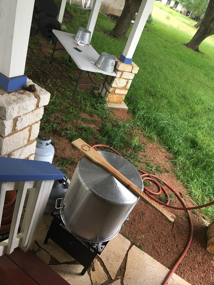
The annual fit inspection

The setup

The setup

The fixings

The fixings

Prep

Prep

Aliens!

Aliens!

The Boil

The Boil

The Finale

Into the trailer the prop went, and to Frank's we drove.
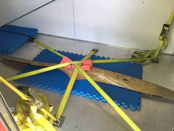
All tucked in

All tucked in

Of course, it took us 15 minutes out of 3 hours I spent there to fix it. The rest of it? Well, what can two guys who're crazy about airplanes do at one of those guys' shop and hangar? Hmm... What could we do? :)

The weather was swell, and I was in a good mood - and airport was on the way back from Frank's.

So, I went straight to the airport.

The prop went on beautifully.
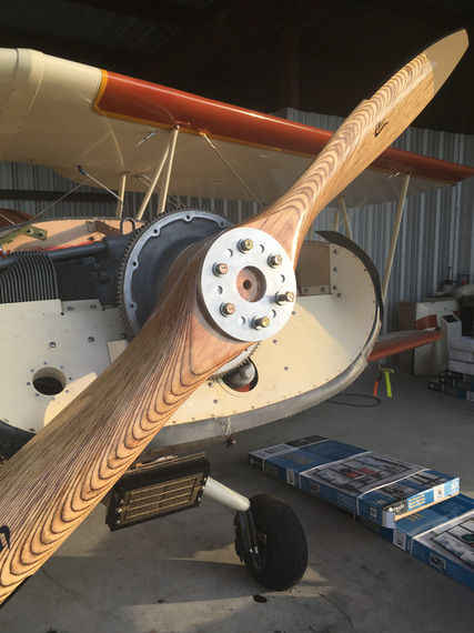
Finally, on

Finally, on

It was nice, sitting in a running, shivering airplane, to watch the sunset. If you looked up, it almost felt like flying. With the buzz, the shake, the smell and the noise.
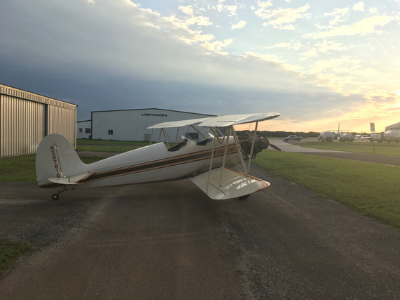
The Sunset

The Sunset

A couple days later, I went back to the hangar, sprayed the engine top and replaced spark plugs with desiccant.

Now, I can focus on the electrical mess...
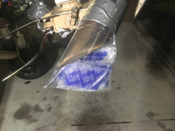
The Muffler plug

The Muffler plug


There are three simple rules for making a smooth landing. Unfortunately, no one knows what they are.


Up ↑
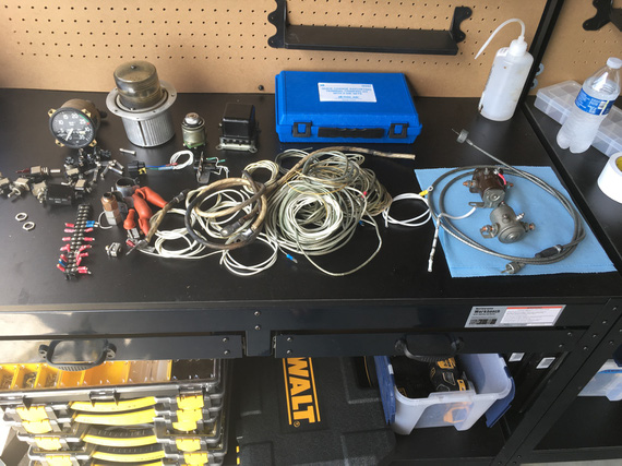
The Flying Fire Hazard

...sparks galore!


On: May 16, 2019
In: [Chickenhouse Charger] Electrical Rebuild
Tags: 6781G, MA5 Charger, Annual, electrical

This thing nagged me for a while. The Charger did not have the Field breaker. For that matter, it didn't have the Alternator master breaker, either.

It had this weird "main buss" breaker for 60 amps, but that didn't look like the Alternator breaker to me.

So in between dealing with other things after having decided to put her thru Annual in 2019 a bit early, I was running around with my multimeter, tracing wires.

Initially, I quickly discovered that some lines were definitely not fused; like Battery -> Main Buss line, and thought I'd put inline fuses into them, and be done.

She has an old charging system; a mechanical switching voltage regulator, and a Delco Remy alternator seemingly from a tractor:

The old Delco-Remy

The old Delco-Remy

Voltage regulator didn't make sense. It had 4 wires (should be 2: supply and field output, or 3: supply, sense, and field output).

Alternator didn't make sense. Instead of 1 wire for Field input, it had two wires.

Additionally, Battery Contactor didn't make sense. One terminal had a wire going to it. The other was grounded....

Interlude

Battery Contactor is an interesting point here. Normally, one terminal is connected to the "always hot" side of it (basically, directly to the battery) and the other goes to the Master Switch. Master Switch turns the Battery Contactor on by grounding that wire, providing the negative side to the circuit. It's a safety thing. If that wire breaks, it'll either turn the electrical off (open circuit), or it will keep it turned on (short to ground). That's it.

But, one of the terminals on the Battery Contactor was grounded... that means, that the other terminal (the wire coming from the Master Switch) must provide positive side??? Huh? But where does it get it's power from?

Tracing

So to tracing we went. I spend maybe 10 hours trying to find diagrams and understand that alternator and voltage regulator hookups.

And me tracing it spelled my doom.

The Diagram

Now, I didn't trace the rest of it. Just the main distribution system. That was enough.

Shall we?

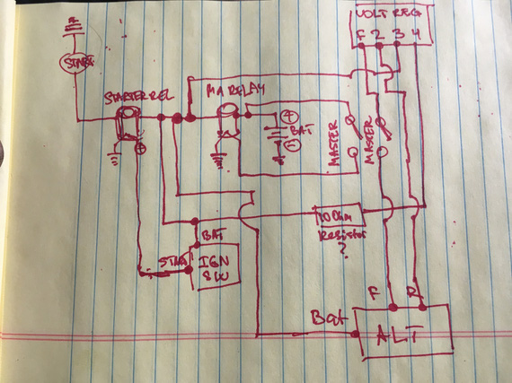
The current  main power system of the Charger

The current main power system of the Charger

Yep, the diagram is missing the main power buss. It's dangling off of the same spot where everything else that's interesting is - the Battery Contactor (marked MA RELAY) <-> Starter Contactor (marked STARTER REL) link.

So let's see what we have here.

  • Lots of unfused wires. Do you see a single fuse here? Nope. That's because there aren't any. All the fuses are further downstream, off of the main buss.
  • Voltage Regulator has this extra wire running to / from cockpit that isn't really necessary and could've been kept on the hot side of the firewall (terminal 4 wire)
  • Alternator field broken at output (F->ALT) rather than at input (battery -> terminal 3)
  • And the best part? Always hot wire that you can't turn off between the battery and the Master Switch to turn the Master Solenoid on.

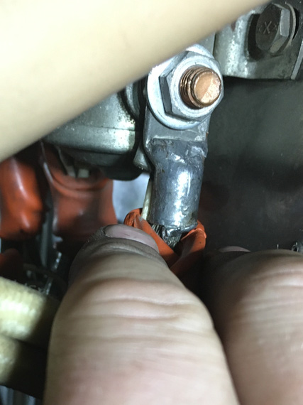
That last bit bugged me. I couldn't find the damn thing. Even before actually tracing it, I knew that if the Master Solenoid is switched on the "hot" side, it needs to get the power from somewhere, and that only could be battery. But I didn't see any wires on the always hot side of the Master Solenoid. Only when I traced it, I actually traced the physical wire to where it goes, and then found it. It was so tucked behind the battery -> Master Solenoid wire that it was invisible:

This little !@#!S@#....

This little !@#!S@#....

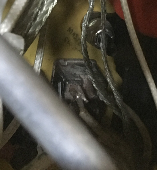
Oh; and by the way, the Master Switch is the only switch that's soldered in, and w/o any good insulation around the terminals, and over-stripped wires. So that's just waiting to short, and the magic smoke that'll be let out behind the panel when that shorts can't be stopped (always hot wire, remember?)

Master Switch

Master Switch

The Wires

So I kinda went backwards here; but I thought it'd be easier to see the diagram first.

Let's see.

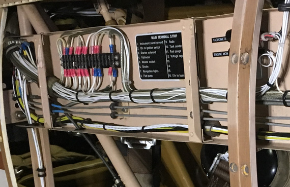
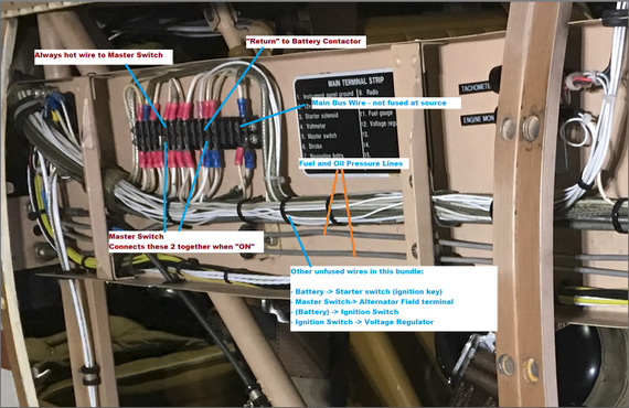
Most of connections are made on this very nicely marked terminal block:

The terminal block

The terminal block

All the switched power comes out there, and every wire is marked. This actually helped a lot in tracing. This block is on the side of the plane, right next to the front hole's backrest.

You know what threw me off the most with that damned always hot wire (I ended up tracing it physically)? It's how it's hooked up.

Yep, it is hooked up to that terminal block. To the terminal... that is marked.. (drumroll).... "Master Switch".

Wait.. this actually makes sense... But where's the "return" from the switch?

Ah! It's the wire that's marked.... drumroll... "Fuel Gauge"!

So really, let's look at what's going on, shall we? Zoom in the image below, it's annotated.

Untangled

Untangled

So let's see. We've got this bundle of wires, a lot of which are not fused, and one of which is always hot.

The Main Buss wire is the thickest one (10 gauge maybe?) that's not fused between this buss bar and the source (engine compartment).

Oh, did I mention that this buss bar is on the side of the plane near the rear instrument panel (so that 10 gauge run, and the rest of the harness between firewall and the panel is about 30 inches long)?

What else do we see there? Oh! The two little 1/16inch thick aluminum lines carrying.. fuel pressure (and oil pressure).

Shall I say more?

Shall I say that there's a fuel tank in between the front hole (passenger) and the firewall?

That the wires run along between firewall and rear cockpit along that fuel pressure line (to fuel pressure gauge)?

That if one shorts to this very nearby fuel pressure line, it'll burn a hole straight thru it, and then ignite the gas that'll start coming out?

Yep.

Can I fix all of that?

Sure. But rewiring will be much much easier, because I have to touch pretty much everything. Re-running half of individual wires in a bundle is much harder than re-running them all.

So, I made a decision to rewire the plane... Sigh. Looks like I won't be flying for a looooong time.

Oh, and tell you what. Tracing wires on a biplane is dangerous. I ended up twisting my knee and pulling a muscle while trying to get behind the panel so badly that I couldn't walk (or sit) for 2.5 days :(.


Some pilots will make an emergency out of a bad magneto check. Others, upon losing a wing, will ask for a lower altitude.


Up ↑
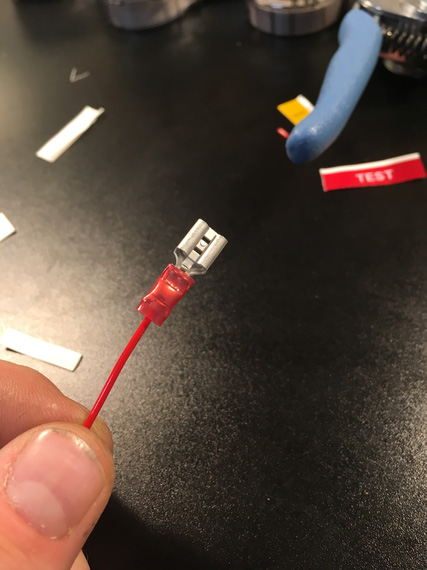
Annual 2019: The Cowling Conundrum

...Comanche, no Comanche?


On: May 15, 2019
In: [Chickenhouse Charger] 2019 Annual
Tags: 6781G, MA5 Charger, Annual, baffles

Baffle seals on this plane are original reinforced neoprene rubber, and they were in pretty beat up shape. There is a lot of gaps, they sag in places, making the seal really not that good.

So one of the things I decided to do is to redo them.

Pardon the cruddy pictures; but those ones are the only ones I have :(

The Nosebowl

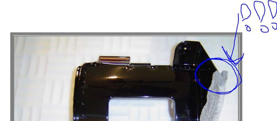
One of the things I noticed immediately is that baffle seals were turned the wrong way in the nosebowl area; where the front "air ramp" joins the bottom of the nosebowl.

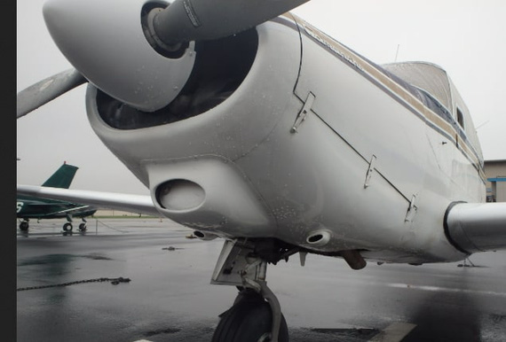
Here's the nosebowl and the front ramp:

Front ramp

Front ramp

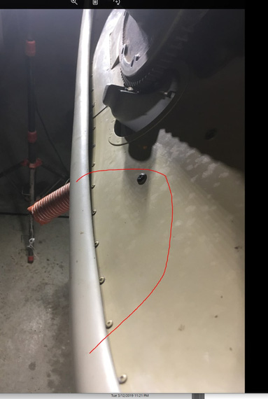
Notice the circled area? Here it is, from the back:

The behinds

The behinds

That marked rubber seal is in the circled area. Notice it's turned the wrong way; "into" the cowling, rather than away from it? Ram air hitting that front "ramp" will "bend it in", and leak into the underside of the engine compartment - precisely where it's not supposed to go.

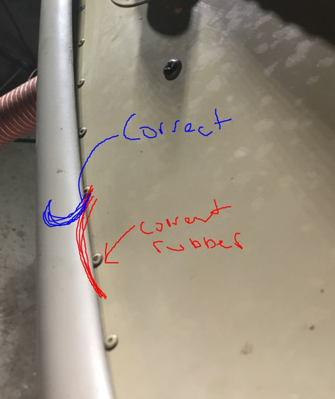
Naive me thought that it was just wrongly installed - the rubber needed to have been folded up and out, "into" the lip of the nosebowl.

Correct and current seal orientation

Correct and current seal orientation

Ha! Well, Remo (the guy who built the Charger) thought different.

There's just not enough room there. Everything is super tight. The seal just won't go there and stay there. There's just no room.

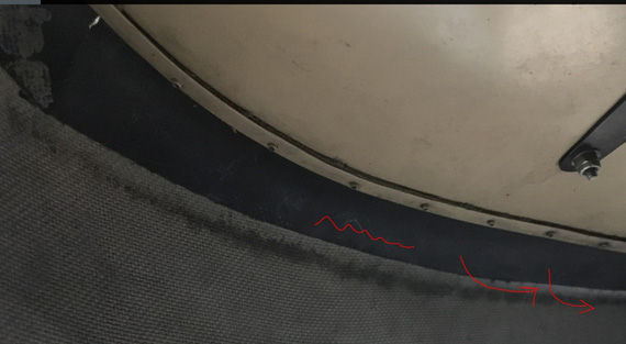
Look at the above two pictures - inside and outside - again. You'll understand why. Use pop rivet line as your reference.

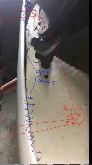
Here's where the problem gets worse. Ramp is really thin - so with just a mild pressure, I can make that gap between the ramp and the bowl 1/4 - 3/8 inches. Guess what happens when ram air hits it... :)

What ram air does...

What ram air does...

Okay, so then I went digging.

I thought this was a standard bowl. I was right!

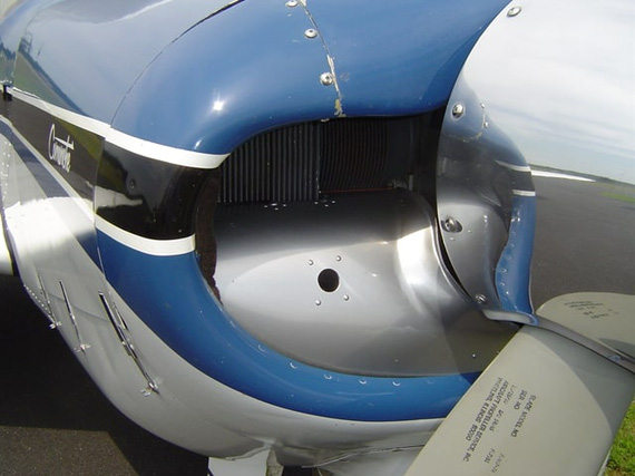
It's an old Comanche single style bowl (I think).

Comanche nose

Comanche nose

Looks similar?  I researched further.

Here's a guy making replacement ramps for Comanches, with some good pictures.

Front ramp on a Comanche

Front ramp on a Comanche

Okay; see the difference? Comanche ramps are curved the other way.

Changer vs. the Comanche

Changer vs. the Comanche

This is cross section. Mine's on the left, Comanche's on the right. Red is nosebowl; blue is this ramp, and black is my baffle seal.

Mine is "concave". Comanche is "convex". So if I got my thinking right, this makes the Comanche version more rigid facing the wind.

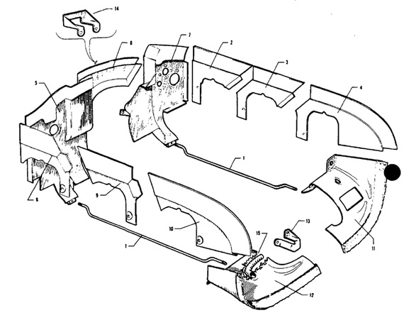
Drawing from the Comanche's parts' manual confirms this proper curve.

Comanche parts manual on baffles

Comanche parts manual on baffles

The parts I'm talking about are numbers 11 and 12, bottom right corner.

But how the heck do they seal them? Notice that the material on the drawing above seemingly has some "dots" on it (as opposed to the rubber material on the side baffles).

Well, back to our "remade Comanche front baffles" guy.

Forward baffles from Comanche Gear guy

Forward baffles from Comanche Gear guy

Felt strip!

Well, I guess that makes sense. Felt wrapped around the front ramp.

Felt strip

Felt strip

Felt is thick and, contacting the nosebowl, I guess, will create a good enough seal if the ramp is rigid enough. I am guessing that Comanche's ramps are way more rigid than mine due to that opposed curve.

So where are we at with all this?

Remo probably built this noseramp himself. It looks very custom. It's too thin and doesn't have rigidity - ram air will flex bend it "into" the cowling. It's not sealed properly practically along all of that bottom edge between the bowl and the ramp.

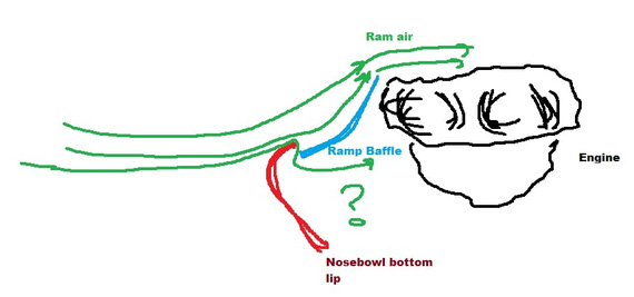
The only hope for it is that it's aerodynamic-ish and looks like a "dozer blade" - curved up. Maybe the nosebowl lip deflects the air enough for it not to go under too much:

Airflow diagram

Airflow diagram

Can I replace the current rubber seal with felt?

Maybe. The front of the engine moves. The ramp's aluminum is very light - I am afraid that if I were to add any reasonable quantity of felt to it to hold the seal tight it will warp the aluminum via relative motion of that ramp (hooked up to the engine) rubbing on the bottom of the nosebowl. Or worse yet, make a hole in the bowl.

Can I replace the ramp? Well, everything's possible; but that's a massive undertaking. That ramp / nose baffle, Comanche-style, has that compound curve, and I don't have time or skill to do it fast. 2 months? Maybe, if I get lucky. BTW this is probably why Remo did it this way - because his is just an aluminum sheet, wrapped around the front of the engine, "neck cone" style, and cut to fit.

So, what do I do?

After discussing this at length with my good friend Ben, we settled on testing this out first to see how bad the air flow going "under" will be. I can mark the bottom of the nosebowl with some tinted oil, and go fly. Oil streaks will tell me if the air is flowing under a lot, or not so much.

I'll also replace all the other baffle seals, which will improve cooling. There's a lot of gaps to RTV, too.

I don't want to replace the bottom nosebowl ones, because actually there the rigidity of old neoprene rubber seals should help...


The nicer an airplane looks, the better it flies.


Up ↑
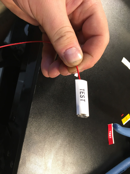
Annual 2019: The Rest of April

...and 1/2 of May


On: May 14, 2019
In: [Chickenhouse Charger] 2019 Annual
Tags: 6781G, MA5 Charger, Annual, Rotec TBI, baffles, prop, fabric

Well, as usual, I got too focused on the plane and the mess I got myself into; and didn't log things as they went...

I will split the notes in multiple posts; by theme / subject. Just general notes here.

Annual, Continued

We got together with John, my IA, and continued working on the plane early April.

We pulled the prop, so that I will have access to baffles (I wanted to redo them).

John re-riveted the air takeoff flange back to the front ramp.

Meanwhile, I started disassembling the fuel system to get to the screens, including the oil sump screen, and clean them.

Airbox off

Airbox off

TBI intake airflow straightener

TBI intake airflow straightener

Okay, stop right there. See that fuel inlet, right above the air intake? See the little smudge of dope around the inlet fitting? Yep. Teflon dope. Rotec explicitly tells you not to put ANYTHING on there - there's a copper crush gasket behind that fitting.

TBI screen

TBI screen

TBI crush gasket

TBI crush gasket

See all that dope above? Okay, that thread on the TBI is a female thread. Dope will be all in it, and guess what will happen when I screw the fitting back in? Yep. It'll go into the TBI fuel galleys. Right to where that spray bar is with tiny little holes in it. Not Good (c).

TBI holes plugged

TBI holes plugged

Intakes

I noticed evidence of possible intake leaks, so without "burping" the engine, decided to pull the intakes and replace the gaskets. This is my karma. I did that on the Cheetah just a year ago, and scraping remnants of one of those gaskets and re-chasing the threads took me about 10 hours; maybe more.

Also: interesting note: she has intake tube clamps on studs and not bolts like every other Lycoming I've seen. Old, narrow-deck cylinders :).

Prop

When we pulled it, bolts were in the thru holes on the wooden prop really tight.

Pulling the prop

Pulling the prop

She has the prop made by Frank Johnson of Performance Propellers fame, and after contacting him, he just suggested to re-drill the holes and re-coat them inside with something.

Well, I got me a 29/64 (1/64 oversize) reamer, and went to town.

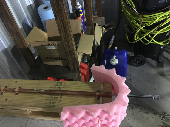
But first, I needed a rack.

My prop rack

My prop rack

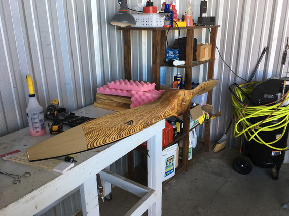
Built with a 1/2" pipe, some foam, pipe brackets, screws, 2x6s screwed to the table, and my 3/8" drive extension rod. You get the idea :). Redneck engineering galore.

Prop on the rack

Prop on the rack

This whole thing was happening over a few days by the way; and when I finally got my reamer and had time to deal with it, the holes.. extended. Wood moves!

Hey, we had much rain then, and prop "swelled" a bit methinks.

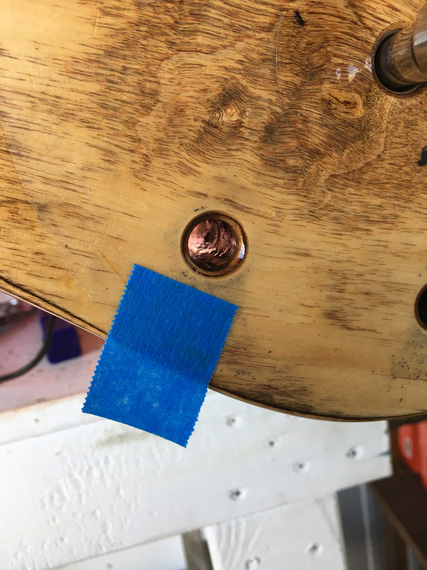
But I still decided to fill the holes as much as I could.

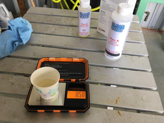
Even got me some nice scales for mixing System Three ClearCoat.

Mixing

Mixing

A filled hole

A filled hole

Backside

Backside

Interlude

Hey, look, I got a nice neighbor next door!

My new neighbor

My new neighbor

Fabric

Fabric on this plane is old. Flyable from what I am being told by experts, but old. Cracking, peeling paint.

Original logs say that she was covered in Polyfiber. But the current finish looks more like Imron and the company - "flexible" automotive poly. It's cracking and peeling around areas of high wear (prop wash, etc).

Sad fabric

Sad fabric

Sad, sad fabric

Sad, sad fabric

John (my IA) wanted to take a Maule fabric tester to it; but I didn't want holes in my wings.

I discussed this with a few guys that worked with fabric their whole lives, and we came to a consensus that for now this is fine. Will just fill with silver, and keep on flying. Incidentally, that's what Glenn has been doing, too.

Full Stop

I worked on baffles a bit, but then, everything went downhill. We'll talk about baffles in the next post. And the downhill part, afterwards :).


The owner's guide that comes with a $500 refrigerator makes more sense than the one that comes with a $50 million airliner.


Up ↑
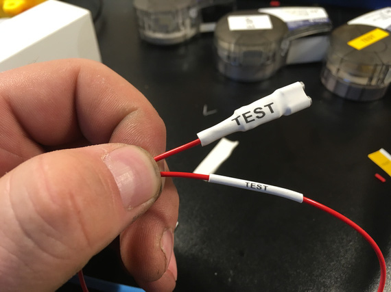
Annual 2019: April 6

...wing root fairings


On: Apr 06, 2019
In: [Chickenhouse Charger] 2019 Annual
Tags: 6781G, MA5 Charger, Annual

Only had a few hours today, so decided to concentrate on taking off the wing root fairings. As I mentioned before, the "back-side accessible" screws were set up to have nuts on them rather than nutplates. Well, I don't know about that accessibility....

It ended up being 3 hours for ~30 screws.

Root fairing off

Root fairing off

Most of them on the back side of the wing require you reaching with a wrench thru the rear cockpit, and my arm is just barely long enough to do that successfully. Since nuts are nyloc, no way I can hold them with my fingers - they need a socket.

Some of those nuts are in a U-type channel over which the fabric is glued, and some of the holes are off-center: making it impossible to put a socket over them.

I could've ground a socket down; but I don't have a grinder - so especially one of the nuts took a while to get off. And oh, you have to do all that without dropping the nut and the washer onto the floor (and having them go into the tail). So the process looked like this:

  • Get your hand in, try to put the socket over the nut.
  • While holding the ratchet, try to put the screwdriver into the screw w/o missing it and poking a hole in the fabric.
  • Undo the screw, almost.
  • Remove the socket, take a strong magnet.
  • Finish undoing the screw, hoping that the magnet will catch the washer and the nut.

Having magnetic sockets helped. They weren't deep enough to grab most of the fully tightened nuts because screws protruded from them. I used them as magnets sometimes, and sometimes used my magnetic "fishing for lost hardware" probe.

Now I'm writing this, I realized what I should've been doing is using a long extension and a 90 degree adapter on my socket. Damn! But this still doesn't solve the problem with some of the nuts that were hidden almost behind things that were in the way (ie, a trim control wheel's attachment structure that's welded into the fuselage).

One of those pesky nuts

One of those pesky nuts

I'm considering replacing those nuts with Tinnerman-type and screws with sheet metal screws thru Tinnermans. I'd put some anti-chafe tape inside the U-channel, and then Tinnermans on top of it. Since Tinnermans are long, when undoing (or tightening) the screw, they will turn and touch the side of the U-channel, which will act as a wrench.

Wing attachment - right side

Wing attachment - right side

And that's literally all I got done today. Just took those damn screws out.


When you’re sitting in the rubber raft looking up where your airplane used to be, it's too late to check the flight plan


Powered by B-Log, which is based on Pelican, heavily plugged and themed.

© Copyright "79FT". All rights reserved. Feel free to cite, but link back to the pages cited.

This website only shows how I did things in my various projects. These pages are for information and personal entertainment only and not to be construed as the only way, or even the perceived correct way of doing things. You are responsible for your own safety and techniques.