[79FT]: Building Things |
 |
Annual 2019: March 30
... getting familiar
| On: | Mar 30, 2019 |
| In: | [Chickenhouse Charger] 2019 Annual |
| Tags: | 6781G, MA5 Charger, Annual |
Decision
After getting the Charger, I have decided to fix a few basics.
- Clean plugs
- Change oil
- Give her a good look over
Getting a bit ahead of myself, a series of coincidences (airport closed, baffles' condition, intake leak, and others) made me decide to go thru the annu... sorry, Condition inspection (damn, will have to get used to new nomenclature :) ).
Notes
Cowling came off.
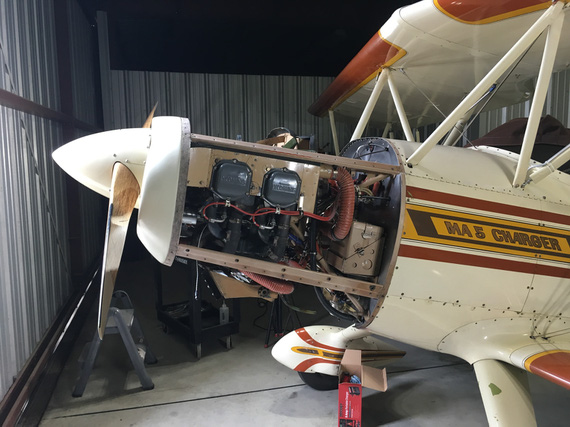
Cowling off
Discovered a few booboos:
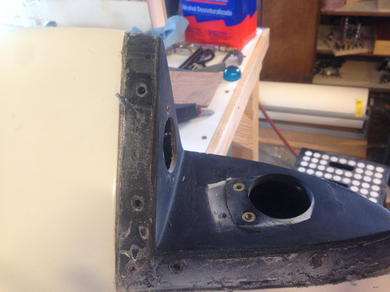
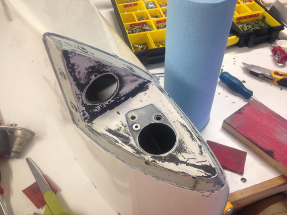
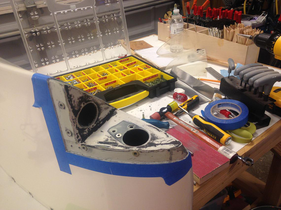
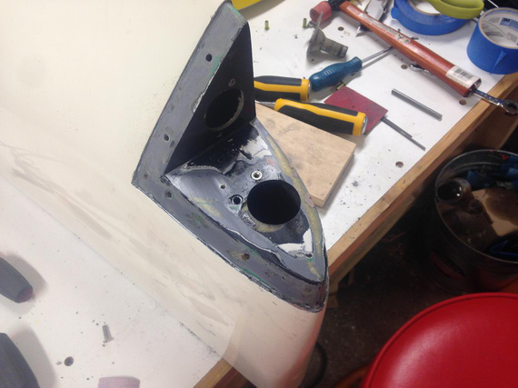
- Cracked cowl inlet ramp: need to stop drill.
- Baffle seal behind the inlet ramp is turned the wrong way (Glenn was complaining about high temps - one of the reasons, hmm?).
- Top baffle seals are too hard and sag in few spots.
- One of the air take-offs off the ramp has almost un-riveted itself.
Since I will need some helps with skills and tools with riveting, and we'll need to pull the prop to change (and turn the right way) the seals, decided that I will put her thru annual.
Studying the systems (I was mainly concentrated on fuel and other al lines and hoses to see where things go), discovered a few things, too
- She has the Rotec TBI-40-MKI TBI installed, which requires a 40 mesh filter upstream of it. The only filter besides finger strainers in tanks is gascolator, which goes down to 72 micron (0.003) only. Need to get a hold of Rotec people and discuss this situation.
- The "low" end of the tank (in 3-point attitude) has a very nice drain fitting + drain cock draining behind the cowl. I am seriously considering adding a quick drain there - that is the lowest point of the tank in 3-point. My thinking is: water collected in the tank, goes to that lowest point; but there's not enough of it to go thru the take-off (which is in the middle). Then, when I raise the tail, it slushes forward, goes into the take-off, and reaches the engine right when I am just off the runway. Not Good.
- Some un-critical drain hoses are clear vinyl and hard as a rock. For now will replace them with clear polyurethane, and if that hardens, with rubber.
- TBI needs positive stops on the throttle quadrant. Need to check if they're present and adjust as necessary.
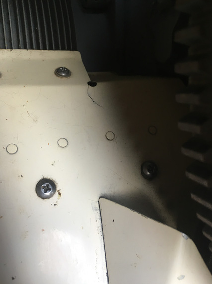
Crack in inlet ramp: stop drill
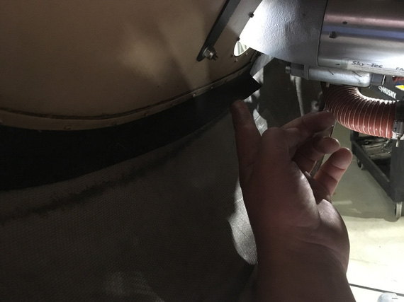
Inlet ramp baffle: turned the wrong way
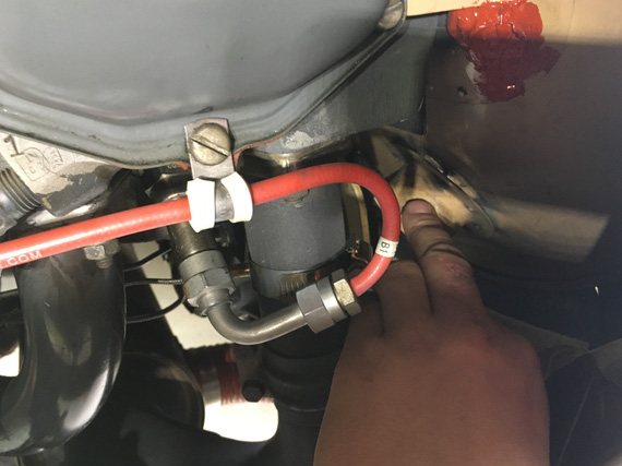
Inlet ramp's take-off flange - un-riveted itself
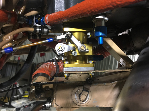
TBI
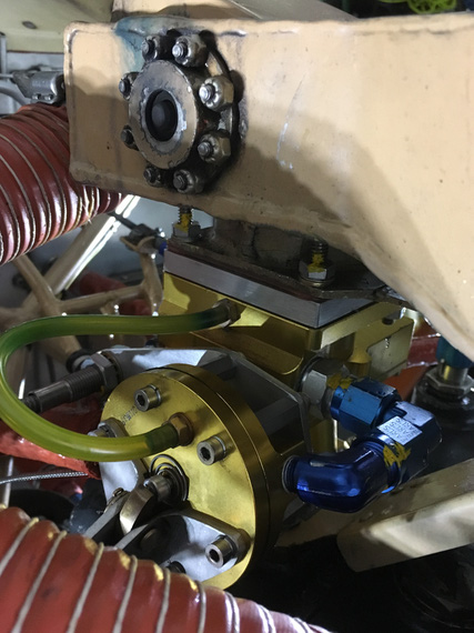
TBI - Regulator Side
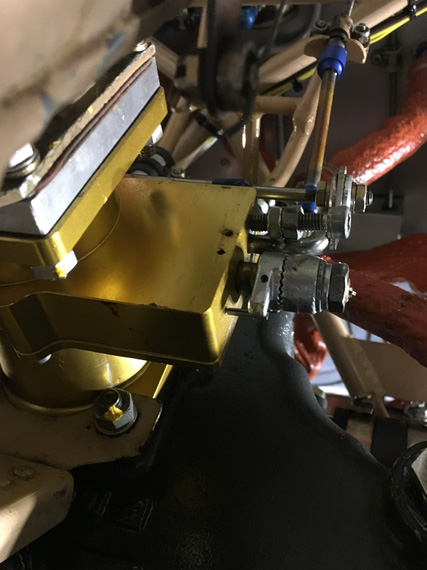
TBI - Throttle linkage
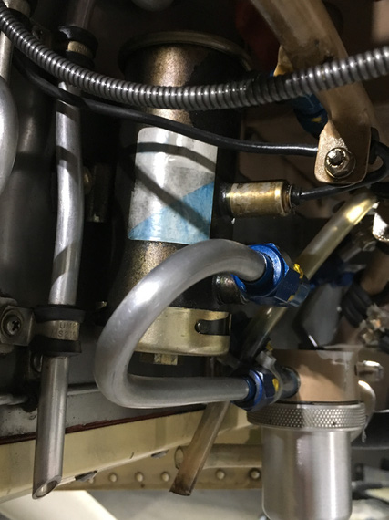
Electrical fuel pump and gascolator
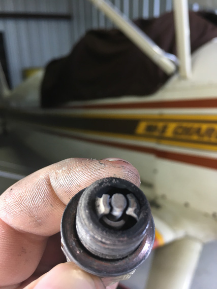
#1 bottom plug - in pretty good shape
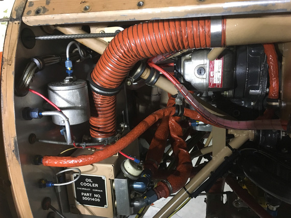
Engine compartment right side
Fairings
Spent the rest of the day taking off fairings and access panels. This is the first thing I thing could've been done better here methinks. Everywhere where it was deemed that the back side would be "accessible", Remo used #6-32 nyloc AN nuts on machine screws instead of nutplates. Well, some of those nuts are not accessible, and I gave up on quite a bit of them around the rear wing root fairings.
Need to standardize on fasteners' length so that I don't juggle 10 different screw sizes.
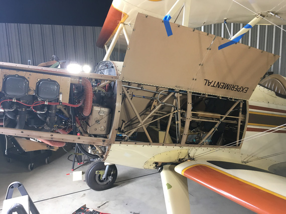
Gotta love that easy access!
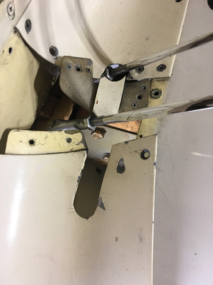
Flying wires' fairing
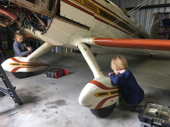
My laborers for the day working on wheelpants
Gravity, it's not just a good idea, it's the law.
Up ↑
A Long Planned Trip
... for Glenn
| On: | Mar 27, 2019 |
| In: | [Chickenhouse Charger] Blog |
| Tags: | flying, 6781G, MA5 Charger |
Fade In
I met Glenn and Judi in 2014.
This was my second Oshkosh, and the first time I noticed the Biplane Forum's Beer'O'Clock thread.
We had two "events" that year: one in the Vintage at the awesome Piper Pub (yep, the spelling is right - it was a Tri-Pacer with the baggage door that had a beer tap. The guy who owned it claimed he had an STC; but paperwork got soaked in beer and was drying somewhere). We sneaked in a large cooler of Austin sour beer then, hauling it all the way from the opposite end of Camp Scholler. I met Glenn there, and later that night washed out in his camp and was fed with a kick-ass grilled cheese sandwich, and met Judi.
The second "event" was at Glenn's airplane, parked near Homebuilder's HQ. It was a beautiful Marquart Charger, I learned then; a 1987 Golden Lindy recipient, built by Remo Galeazzi in Petaluma, CA.
That biplane was beautiful; just the right curves and not as aggressive as more modern ones like Pitts and Skybolts. It looked straight from the 1930s, with wooden prop tipping the nose. I fell in love with it.
In 2015, we've had a good crowd around the plane.
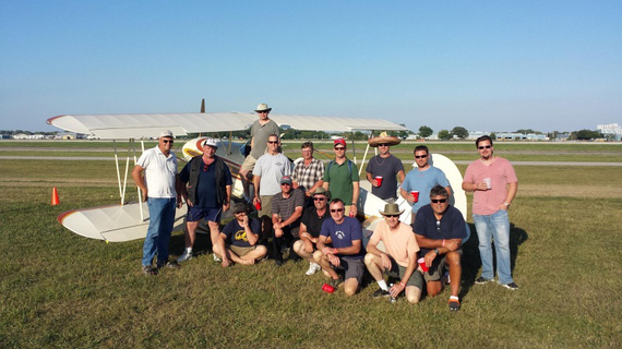
Oshkosh 2015 Biplane Forum Beer'o'Clock crowd
Glenn's Charger became a traditional spot for these beer get-togethers, and we became friends who only met at Oshkosh; but to me it felt like I knew Glenn for my whole life, and 11.5 months between AirVentures felt like hours.
In 2016, I was finally around Chicago where Glenn lived, and he took me out to his home field, Poplar Grove. Man, what an airport! Just the right kind for his plane. We spent a day there, and I think I have seen only one spam can and maybe one RV. The others were a few Cubs, a Twin Beech, a Waco, and the like. A few friends showed up, and that day I got a ride in an AcroSport bipe, and later in the evening, finally, in the Charger.
Oh man. I flew a couple sport biplanes before; and while I liked them, they were too much for this lazy guy. Just a bit too twitchy and too sensitive.
This plane? It flew just like a Grumman. Perfect control harmony. Perfect, light forces on both elevator and ailerons. It fit like a glove.
Then, that night, by the way, I started seriously reconsidering building a Skybolt (BTW, this site was started as a Builder's Log for a Skybolt). I flew one, and while I still liked the plane, I liked the Charger even more.
Especially with it's more "classic" looks (and come on, admit it, we pick biplanes for looks), and it's perfect flyability.
In 2017, we did Beer'o'Clock at my camp (I forget why.. maybe the Charger wasn't around).
And later that year, Glenn told me he's thinking about selling it. He got too much stuff on his hands, and didn't want to neglect the Grand Champion.
I thought for about a day. I loved my Cheetah, and I loved the fact that it was a "normal" airplane. I could take my 2 year old son up in it. Not in a biplane. I could take "normal" people up in a Cheetah. Not in an open cockpit biplane - at least, it's a bit more.. rough, shall we say?
But I couldn't let the plane I loved just be sold on the Barnstormers; so the next day I told Glenn I'll take care of her when the time comes. I was overwhelmed, and honored to have a chance of taking care of a piece of aviating and homebuilding history.
The Plane
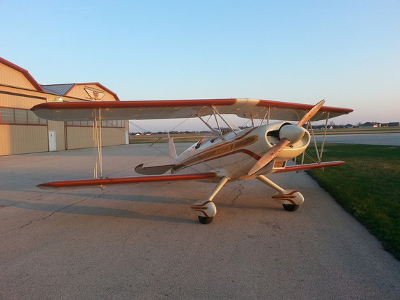
The MA5 Charger
She was built in 1982. From what I could gather, she was started in 1977. There were two guys who built two MA5 Chargers in a chickenhouse in Petaluma, CA. Glenn's plane was built by Remo Galeazzi, and won the Golden Lindy in 1987. The other Charger won too by the way, some years earlier :).
Remo wrote a really nice article for Sport Aviation about both planes.
Here's another article about the plane.
Glenn changed it a bit, adding the smoke system, changing the prop to wood, and tweaking the induction and fuel systems. But the plane stayed all original mostly - original engine, original fabric, and such.
Oh, and it's the Charger on Wikipedia :)!
Logistics
I told Glenn to give me 6 months heads up, so that I could work out the logistics.
See, I have lots of hours to be very comfy flying any common tricycle single. I didn't have enough experience to haul a taildragger bipe across the country (Glenn moved to CA by then). I would have to learn how to fly it comfortably before embarking on the trip; and figure out the logistics.
But then, things went much faster than I thought.
At Oshkosh 2018, Glenn was telling me he's about to sell the plane. I realized I didn't have time to train enough, and that it would be better to train in the Charger from the getgo. So the working plan became me renting a large-ish truck, and hauling the airplane over to Texas with wings off.
And then, Glenn offered to fly the plane over himself, as a good bye to her. I couldn't refuse.
September 2018, Glenn told me he's gonna fly the plane over soon. I put the Cheetah up for sale, and said my last goodbyes to her November 21, 2018. Then, life and weather intervened, and we couldn't set the trip up till last weekend.
'It's warming up', Glenn texted me a week and a half ago.
A week after that text, he was wheels up en route to TX, with Judi in the front hole.
The Trip
That didn't last long. An hour and change later, Glenn was stuck in Bakersfield, just at the southern tip of Central Valley, CA. All mountain passes were blocked by low ceilings...
What's funny was that I was flying.. strike that, being flown from San Jose to Los Angeles, continuing to Texas, the same day Glenn and Judi were stuck at Bakersfield. I saw the damn clouds blocking the passes. They were maybe a mile wide!!!
This delayed them by about 24 hours, but the rest of the trip was fairly smooth. They did a lot of flying after being stuck in Bakersfield for practically a whole day, and some hours the following day.
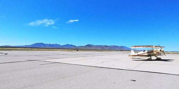
Somewhere in the desert...
Saturday, March 23, at around 10:30 AM Central, they touched down at my home field. We had very little time - their flight back home was in a few hours. Glenn walked me thru the basics. We tucked the airplane away.
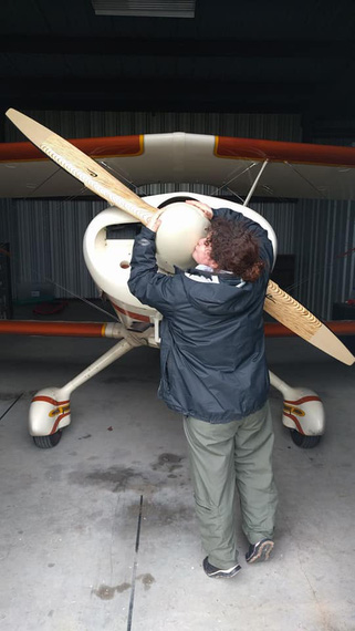
Judi saying bye
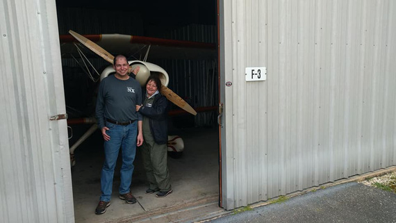
Glenn and Judi...
Quick lunch, and on the way to the airport with the big planes we went. A few hours later, late at night, Glenn and Judi were back home.
Fin
It was all so fast, I was in the state of... denial? and disbelief? I started becoming overwhelmed when I got back home in the evening on that day, and opened up the logbooks.
Remo's signatures and flight log.
Remo's letters.
Glenn's signatures and notes.
The letter from Remo to Glenn, with a bunch of pictures - just pictures of this Charger being built; mundane almost; but a part of the Champion's history.
I ended up writing this into my logbook:
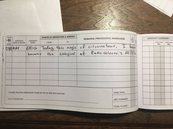
First 6781G log entry in my log book
I now am a caregiver of a piece of aviation, homebuilding, and EAA's history.
And, I am no longer planeless! She needs a bit of cleaning and a touch of TLC, and to learning how to fly her we go!
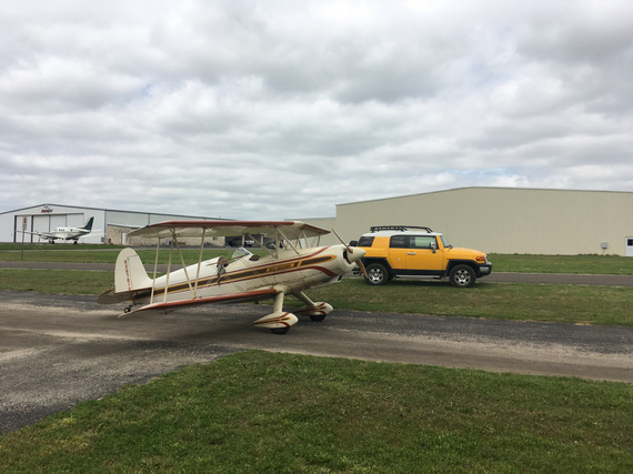
The Chickenhouse Charger!
Better to be on the ground wishing to be in the air than in the air wishing to be on the ground.
Up ↑
Good Bye, Cheetah!
...live long, and prosper!
| On: | Nov 21, 2018 |
| In: | [Misc] Cheetah |
| Tags: | 9891U, flying |
Great weather today. A bit cold, but sunny, calm, and overall very promising.
I rolled out the Cheetah out of her hangar for the last time.
This was a weird feeling.
When you have an airplane sitting in the hangar 20 minutes away from your house, you tend to sometimes put flying off.
It typically goes along these lines.
Hey, it's Saturday coming up. I gotta go bounce around! check the weather Hmm...looks a bit iffy. Maybe I should do this-other-thing-around-the-house-shop-or-whatever-I-hadn't-gotten-around-to. Maybe, I'll go flying after that...
Evening rolls in, you're tired and not up for flying anymore.. Meanwhile, weather was perfect the whole day!
"Next week", you think. And you go out next week, but this time it's something else that pops up and you have to get to it later in the day, and instead of spending half a day bouncing around, you buzz around the pattern for half an hour and go back to your daily messes and stuff to do around the house.
Not every Saturday was like that since I got back to having time to do plane stuff... but often, it did.
But this time, today. It was weird. The knowing that I am flying her for the last time, that I am listening to GTU ATIS on her radios for the last time, the last VOR to be tuned in, last turn direct to the destination, last approach guy handing you over to your destination's Tower...
"Field in sight"...
On a day like today...
Sunny, silky smooth, a touch of clouds, with all the gauges' needles frozen in place...
You remember all the good times you had together, and think... I'll miss you, Cheetah!
I guess, in the Spirit of Thanksgiving..?
Thank you for all the wingovers, low passes over lakes, and river runs.
Thank you for all the kids we've flown as Young Eagles.
Thank you for getting my ass out of that fog along the coast of Madagorda Island (that one was the "bag of luck" to "bag of experience" type thing for sure!)
Thank you for all the fun I had messing with you.
Thank you for that unique kind of smell that your inside smelled with (and my tiger LeRoy who lived in the plane still smells like you!)
Thank you for being a good plane and not giving me any trouble.
I hope I'll see you again sometime! And maybe then, we'll go bounce around together again. Just like the good old times.
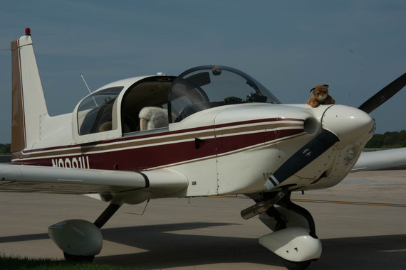
The Cheetah
No one has ever collided with the sky.
Up ↑
Fall Round of Pickles
... out of heavy machinery
| On: | Oct 12, 2018 |
| In: | [Dream Shop] Tooling |
| Tags: | shop, tools |
As we have established before, Fall for Russians is all about pickling things.
Last time it was an O-360. This time, it's tools for the new shop.
My current shop is all packed up and in storage, waiting for the actual shop to be built. Well, actually for the building to be gutted.
When I have built the new house, I have kept the old house. That's what's about to become my Dream Shop. Meanwhile, all my tools are nicely set up in my storage shed, waiting for their time.
I have sold most of my Chinese Grizzly crap I bought before knowing any better, and was hunting good, old, American-made machines for a while.
Okay, I settled for a Chinese-made Powermatic drill press, arguing with myself that it was in mint shape, dialed in with no obvious runout / shake, and would be my wood-only press anyway.
But two most important things wood-wise I still didn't have: a jointer and a table saw. Few had come up on Craigslist, and I would go over to check them out with all my dial gauges and a U-Haul trailer in tow.
I would spend close to an hour with each one of them, measuring all sorts of convoluted alignments and run-outs, only to find something very basic wrong with them.
One of these was a newer (mustard, but still American-made) PM60 jointer. It checked out reasonably well; until I asked the guy if I could adjust his fence square (I wanted to check it's warp by measuring squareness to tables along it's length).
"Sure Thing!" - he said, walked to a corner of his shop, picked up a hammer, and ... WHACK! - ... ... yeah. Call me a WHACK-o, but that is not how you adjust squareness... Not in my book. I felt for the poor machine.
I left, of course.
Another time I spent just south of 40 minutes with a PM66 table saw, only to check it's flatness dead last. Of course, it was so horribly bowed out of shape, I had to leave. And that was a 3 hour drive. Each way, mind you!
At any rate, yet another PM60 jointer popped up on Craigslist, and I grabbed a trailer in preparation of going to San Antonio the next day. That's where the jointer was.
Now, there was a rolling joke with one of the guys from the office - that he absolutely HAS to convince yet another guy from our office, his buddy, to sell me his PM66 saw - or, Russian Mafia will get him! Them both, in fact!
I kept it up for over a year; and I am not sure if that joke had made any contribution to this... but, he called me and said, "Roger is selling his Powermatic! Grab it, QUICK!". Same day as the jointer popped up.
Hah. So tomorrow I am about to go possibly pick up a jointer. Did I just land me a saw too?
I went to Roger's to dial the saw.
Arbor was shot, but trunnions were in great shape, and arbor for PM-66 is not a problem (someone still literally makes them and sells them on EBay). The tables were flat aside from a very tiny dip, a bit dirty at that, but alright.
I decided to pick it up.
So I did land me a saw and a possible jointer!!!
Next day (Friday), I rush to San Antonio to look at the jointer.
It was a green, older one, and it checked out good, except one minor mis-alignment of infeed and outfeed tables. I was trying to tighten them up a touch with gib set screws, and... I broke one of them.
The tables were flat, the motor was good, and the price was reasonable though, so I decided to buy it from the guy - especially after I broke it :).
Didn't take any pictures of jointer in transit... damn.
So, Friday night Im back, barely manage to roll the jointer off the trailer and into the garage, and Saturday I pack my wrenches and such to go break down the saw at Roger's.
See, it was set up with a large side table, router plate insert, and outfeeds - no way I would've been able to load all that; and besides, I don't need any of that aside from core saw. I already have all my router stuff from my previous shop (Incra no less).
It's raining. Damn.
I get to his place - he's gone for the weekend, his wife lets me in and leaves me alone with the saw and my tools.
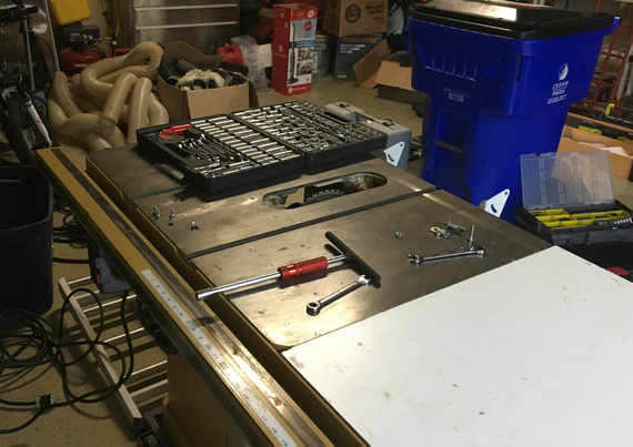
About to begin.
Saw comes apart quite nicely.
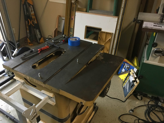
Most of exterior stuff off, table's coming off next
I took off the fence, the side table, and the outfeed rollers. Side table goes into trash. Outfeeds and the fence I will sell (in fact, as of right now I sold the fence already - had three guys call me in the same day!). Yeah, I don't care for it. Incra's TS-LS any day over any other fence (and I have one :) ).
It was obvious no one has cleaned it inside. Likely, ever. Oh, well...
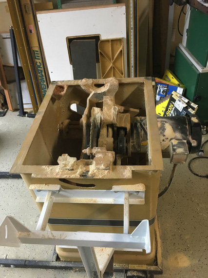
Dust
Remember, I said it was raining? I got a bunch of wrap, and plastic to cover the guts - I wouldn't drive under rain, but even the splash-back concerned me...
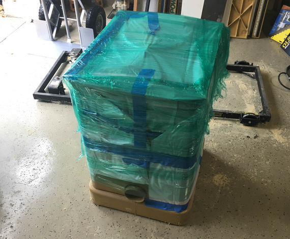
High-Tech Rain Proofing
Funny thing - when I was almost done, we got a nice break in the rain... So, I was able to load the saw up, and got it home without further adventures.
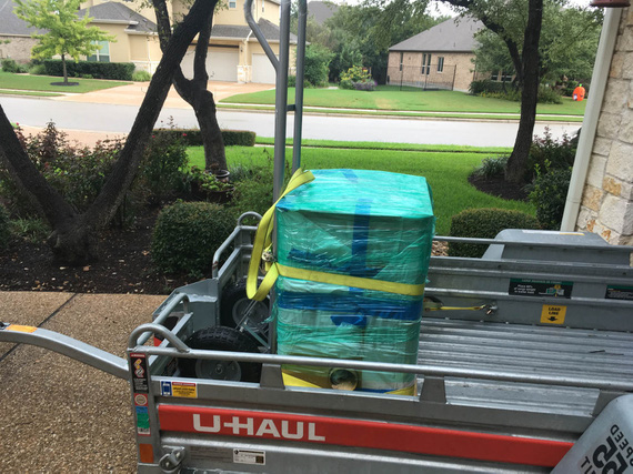
On the trailer
Later, in the next few days, I scraped together a vac and a compressor (remember, all my tools are packed away!), and cleaned it out. All important and not so important unpainted surfaces got a coat of either T9 or Corrosion-X, and she got wrapped back into plastic... The Saw, I will see you in a year or so...
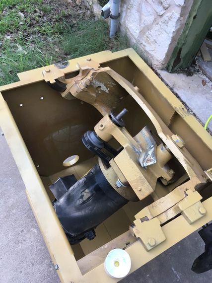
Clean
And the jointer? Well, the jointer was clean already. So it just got wrapped too...
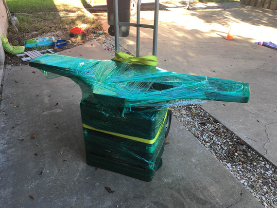
The only pic of the jointer I got
They're sitting nicely in the storage shed now, making acquaintance with my other toys.
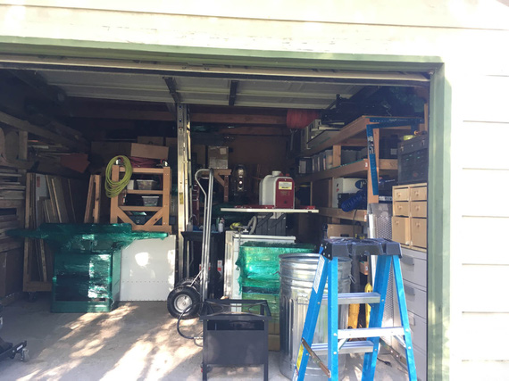
The Shed
And, there. Two most important tools? Done. Pickles out of metal done? Done. What's left?
A mandatory airplane pic, of course! Ken Wittekiend's PA-12 on floats on Lake Buchanan, first time ever I flew a seaplane! That was nice!
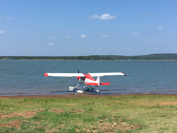
The Seaplane
"MidEx 726, sorry about that, Center thought you were a Midway arrival. Just sit back, relax and pass out some more cookies ... we'll get you to Milwaukee."
-ORD ATC
Up ↑
Back from Three Years of Silence...
... [crickets]
| On: | Sep 26, 2018 |
| In: | [Blog] |
| Tags: | house |
So, the last entry was in July 2015. It's September 2018 now. No, previous entry doesn't count: I have written it 2 hours ago :).
What took me so long? Mostly, the damn house!
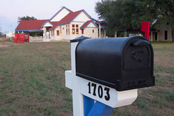
The House
Yes, seems like I pulled the wrong set of plans... again, and instead of building an airplane, ended up building a house.
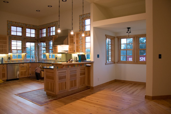
The Kitchen
Damn. Need to sort thru my plans a bit better next time.
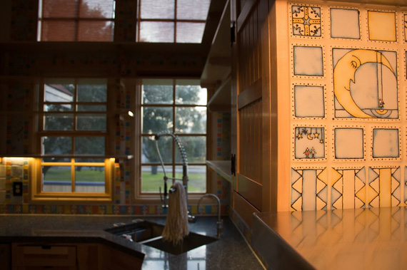
The Tile (each handmade by my kick-ass wife - ~3000 total)
So while we wait for the next project to solidify to the point of having something interesting to write about (it's gonna be The Dream Shop)..., well... I guess, we wait.
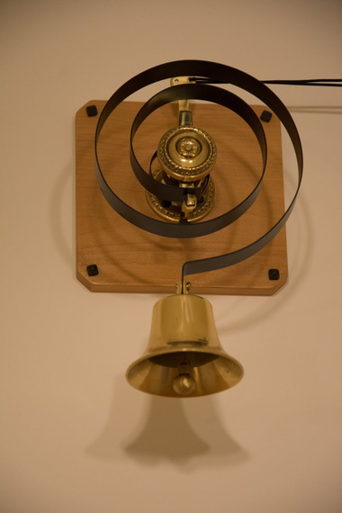
The Door Bell (which still works when power goes out)
If it ain't broke, don't fix it; if it ain't fixed, don't fly it.
Up ↑
B-Log v2
...the long-needed updates
| On: | Sep 25, 2018 |
| In: | [Misc] B Log |
| Tags: | tools, software, website |
After using the setup I did for myself in 2014 for a while, I decided it was time to change things around a bit.
Segway
... so yeah. I needed to add a static page, and I had a bunch of ideas about extra stuff I wanted to do for a while. But mostly, I just needed to add a damn static page, and thinking about coercing the existing setup into doing that with all the pictures I needed there was not making me happy...
... it was also about time I set this thing up so that I could actually log more projects than just a single airplane. Hey, I bet we all know - websites of this kind are mostly created to be later enjoyed by their authors in periods of 'I ain't got nothing better to do than review my old notes' mood ...
Multiple Projects
First of all, I wanted to be able to log multiple projects. The way the old setup was done was it had basically one project, under the section called "Build", and then this dangling catch-all "blog" thing for everything else.
But as you can see, most of articles here actually are NOT about the airplane I was working on at the time - the Skybolt - but rather, other little things here and there.
First thing I did, is I changed the way the files are laid out, and added semantics converting source content's directory structure to "Project / Section" semantics.
Each project now has it's own "sub-log" (that's what time logged is tracked based on). There is still a catch-all "blog" section, and a "default" project that can be configured if one so desires.
Logging
One more thing I realised is that the original version would only allow to log time if it was associated with an article-type entry... Flooding the Internet with tens of pages of "built three more ribs tonight" type stuff just to log time seemed kinda silly, so I added support for plain text log entries.
Articles still can track time; but you can also now have a separate text file with just "Date", "Summary", and "Time Logged" entries - one per line.
When creating the "log" page for a project, entries, being both from articles and from logfiles, are sorted by date, and then ones with articles associated with them will pick their summaries up from articles. Entries coming from text files will be displayed with summaries from log files.
Major Code Cleanup
All this time tracking functionality, structuring articles into projects, and such, were becoming an entity of its own large enough for me to justify clumping it all into a single Pelican's plugin, now called "b_log". I also added a bunch of config options to set up it's behavior.
No Google Analytics
Yeah. I killed it. This site Does Not Track You now. Because there's too much of this crap online.
Fixes, Fixes, Fixes
Too many to count...
- Fixed how logos and icons behave
- Fixed templates in numerous places
- Fixed bugs in image processing and copying
- Images in pages now handled properly - they just weren't. At all
- Decimals in logged times would sometimes show up to 10 digits past the decimal point
- ...
Silliness
And finally, some silliness! I wrote another plugin that adds a "quote of the day" at the end of each article, randomly :) Enjoy; and I hope they will encourage you to read more articles (or at least, scroll thru them to get to the bits of wisdom).
And So, (v2)
I got happier now.
I have changed the B-Log notes to match the new setup, just so that there's one place I can send people to in case they are interested in my setup.
And I'm very close to posting that damn page, but...
...of course, I am restructuring the old content and modifying old pages instead to match what I got now, and writing stupid notes on what I did to the thing. Because, as we all know, making yourself a tool is as, if not more, pleasant, as using it...
To go up, pull the stick back. To go down, pull the stick back harder.
Up ↑
Cleaning up Light Coves on Wingtips for Cheetah
... I hate sanding!
| On: | Jul 03, 2015 |
| In: | [Misc] Cheetah |
| Tags: | 9891U, mechanicing, fiberglass |
In the past 7 months I have been busy building... the crib for the baby. Almost non stop evenings, 4-6 hours a day: the result is good, but this is a "Skybolt Story", not a "Bed Story": so no, I won't post all my projects here :).
Also, it seems like next 2-3 years will be mostly furniture building for this guy.. Oh well.
Meanwhile, I was able to put in a few hours into fixing up the coves in my wingtips where all the lights are.
If you recall, I have made strobe shields quite a while back, but I haven't fixed up the coves. I was waiting for the shields to be painted.
Well, they were during the cgr-30 install, and then I was working on the crib.. So finally, the time has come.
Look at what I had to start with.
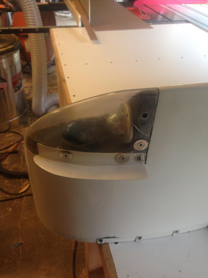
Sad sad wingtip
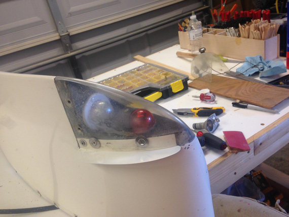
Another sad wingtip
First, all the lights came out. The old plastic lenses went straight into the trash bin. Then, came off the foam padding that goes in between the lens and the wingtip.
All opened up
Cleaned and sanded
I think the above was about an hour of sanding. All old paint came off. Also, the broken rivnut went out (did you notice it? That extra hole was what someone has drilled and used a sheet metal screw to "fix" it instead of drilling out the broken rivnut).
Finally, masked with the first set of masking tape. I was set to repaint the coves.
Masking the edges
The other wingtip was even worse. The cove itself had a huge "dip" in it. Also, some "genius" decided to screw #10 screws straight into the fiberglass... Some threads were all torn up, and I decided to install rivnuts all around to make sure the tips match.
Just disassembled, note the large dip in the nav light area
In with Bondo! Lots of sanding! Oh man, I hate sanding...
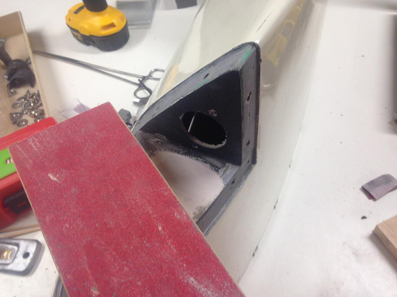
Bondo, and sanding...
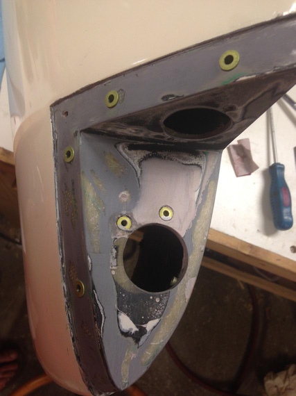
Done sanding
Phew. Quick fit of the strobe shields over the rivnuts, needed to enlarge the holes...
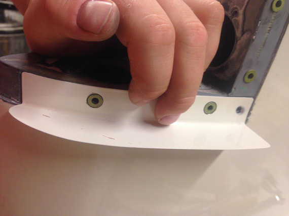
Fitting holes in the strobe shield
And we're ready with the second one.
Now, I wanted to clean up the nav lights housing as well. Originally I wanted to paint both cover and base, but once I cleaned up the base, I decided to leave it as is: apparently, it was nice and shiny after all that 40 year old corrosion cleaned off of it!
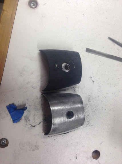
Nav lights covers. Second one was cleaned up as well
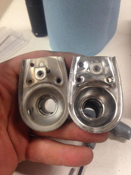
Cleaning nav lights bases. Shiny!
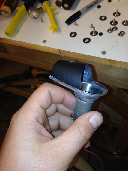
Came out nice after painting!
Then, final masking, and painting. Damn! That didn't go so well. I didn't notice a fairly small dip in the other tip's cove, and the Bondo'd one got some pinholes. Time was running very short so I ended up leaving that as is.
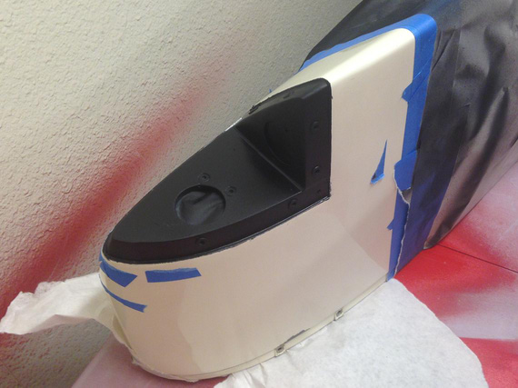
Right wingtip cove, painted. See the dip now?
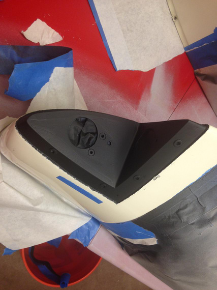
Left tip. That one with pinholes :(
Once the paint was all dry came the time for fitting the foam padding and lenses. And here, I made a fatal mistake: I have installed the padding first. That makes fitting of the lens virtually impossible (at least, for me).
That had produced an unsightly gap of about 1/8 inches. Oh god! I had no spare lenses, and I had to put the plane back together not to screw my partner who needed the plane soon. Very soon.
... I ended up screwing him anyway 'cause somewhere in the middle of me fitting that first lens Max was born and I was knocked out for 5 days ...
... just in case you're wondering: 7lbs 11oz, 20 inches, June 25, 2015, 10:35 am ...
... I still haven't had any chance to get another lens, so I decided to put it back together as is as a memory of me being stupid. Maybe I'll buy another set from Ken in another year or two; and also fix all the dips and pinholes ...
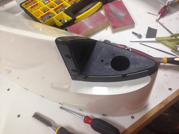
Fitting the foam padding
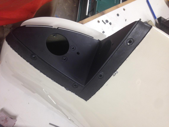
Fitting the foam padding (back side)
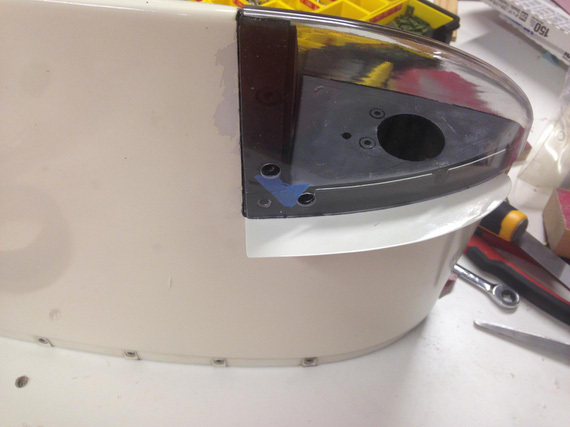
Top/front lens fitting
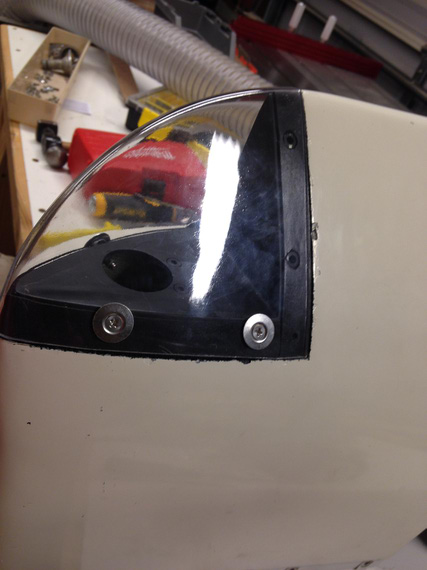
Bottom seams: see the unsightly gap?
I was much smarter with the other lens, and made sure to fit it before I put on the foam padding, and it came out perfect.
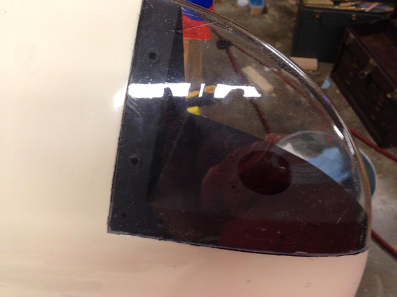
Fitting other lens. See no padding?
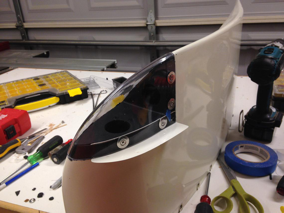
Padding on: and some holes in, too
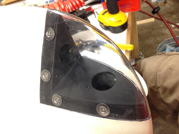
The other side
Then, I've put the lights back in, permanently screwed on the lenses, and I was done!
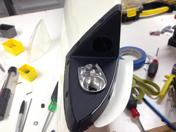
Installing the nav light base
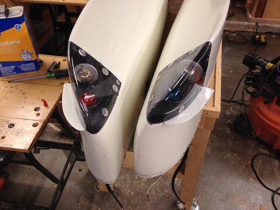
All done!
Much nicer than before, but with some problems. Still, much nicer than before.
Till next time (which-I-dont-know-when-will-come)!
"Approach UAL525 what's this aircraft doing at my altitude?"
"UAL525, what makes you think it's YOUR altitude, Captain?"
-ORD ATC
Up ↑
CGR30 and the Wheelpants
lots of upgrades
| On: | Dec 10, 2014 |
| In: | [Misc] Cheetah |
| Tags: | 9891U, cgr30 |
I'm done with my longest airplane project so far! No, it's not for the Skybolt, it's for my Cheetah. But it's an important one and was a great fun to tackle.
So, without further adieu...
The Cheetah never had an engine analyzer -- and I elected to get one, full blown, replacing all the standard engine gauges. I ended up picking the EI's CGR-30P because of it's roundness, compactness, and me generally liking EI a lot.
So, late August, it was Christmas. I got the box, that had a lot of boxes, with boxes, and boxes inside -- lots of stuff. Probes, aggregator box, wires...
First thing I did was put everything together on my dining table, just to make sure I understand the wire-up and that it works. I have even blown into the fuel transducer and was satisfied seeing it registering some "flow".
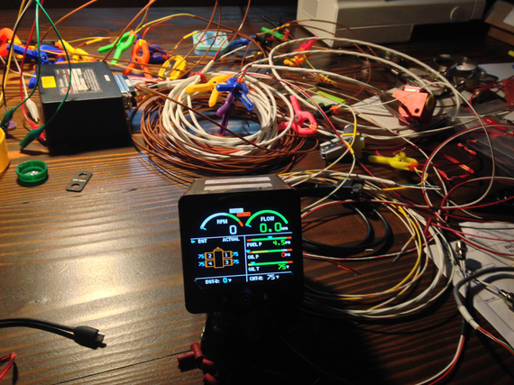
On the bench
And then, the install. The problem was, I also wanted to fly in between, so I had to plan the install in stages and make sure the airplane's flyable in between.
Session 1
First thing was running two out of three wire harnesses thru the firewall (all temp probes, and all pressure and flow transducers). I found a spot on the inside of the firewall for the box, and made sure I had enough length to run to the "aggregator" box.
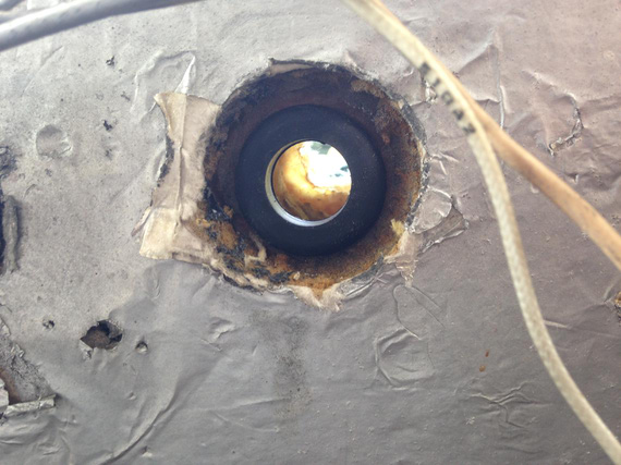
Reused existing hole, new grommet
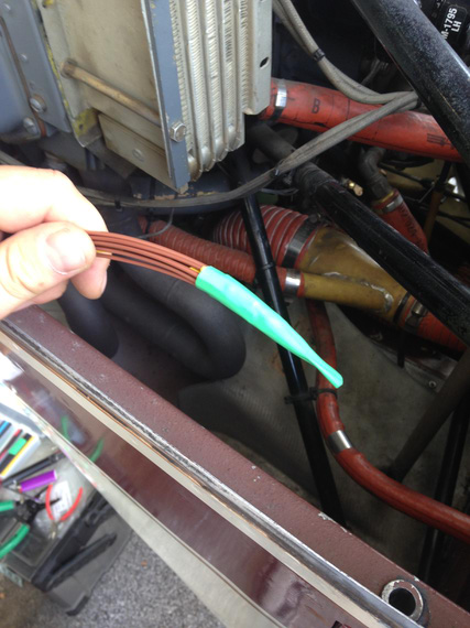
Wires bundled neatly for running thru
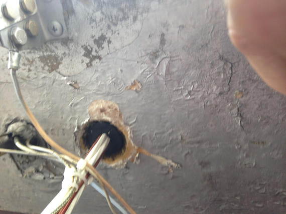
All wires are thru
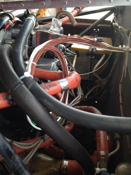
.. and neatly tucked away
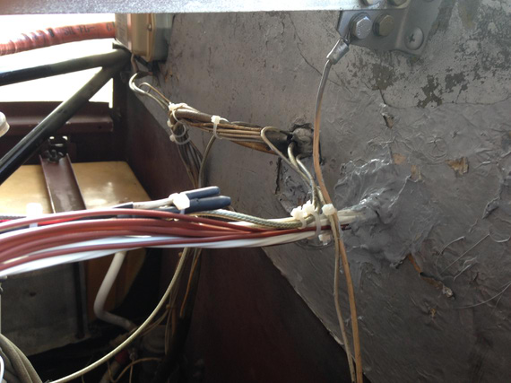
The hole with the wire harness sealed
Session 2
I was planning to fly out to friend's hangar and work on the probes install there. The luck did not cooperate -- very sluggish pull-thru on the engine start and heavy discharge right after on the ammeter hinted at the alternator failure.
Sure enough, it was. I ended up unbuttoning the cowl at the FBO I was hangaring at.
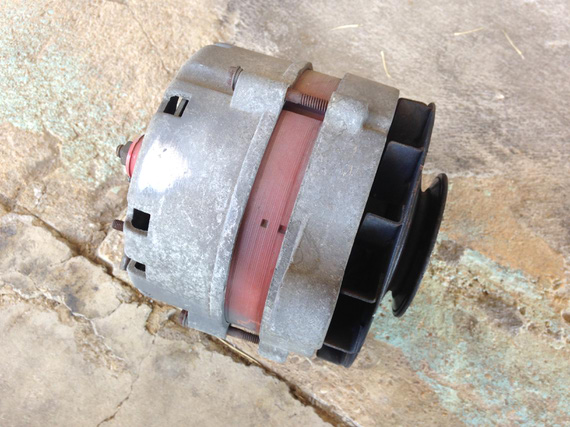
The perpetrator
That day, since the cowl was off and out of the way, I decided to continue and wire up as many probes as I could.
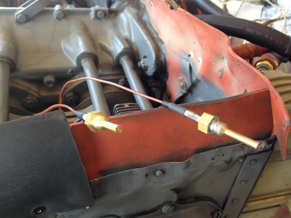
The CHT probes, lubed with anti-seize
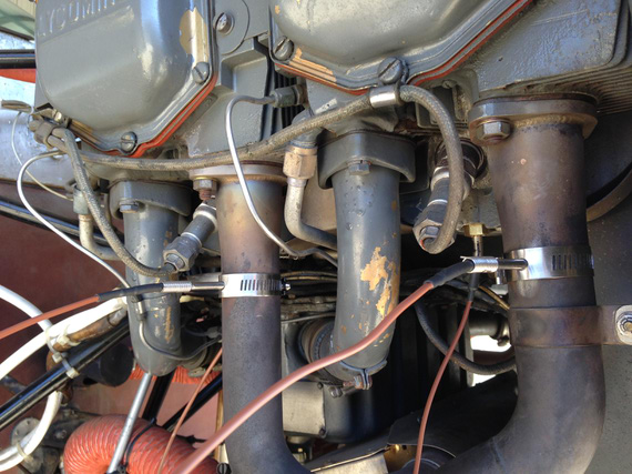
The EGT and CHT probes on one side
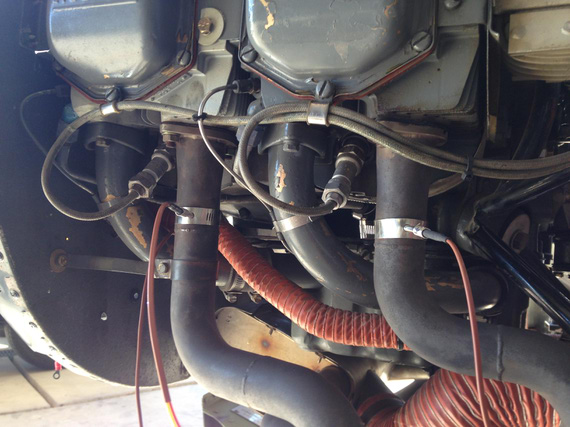
Probes on the other side
Then, came the time of connecting the probes to harnesses. As you saw on the pictures, probes have dinky little wires that aren't protected in any way. I asked EI if I should special-treat them in any way and they said no, but I still decided to get some fiberglass firesleeving from Grainger, and tucked them neatly away. Liked this much better!
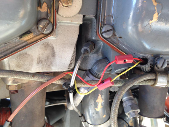
Connecting the probes. Notice the barrel connectors staggered, and fire sleeve
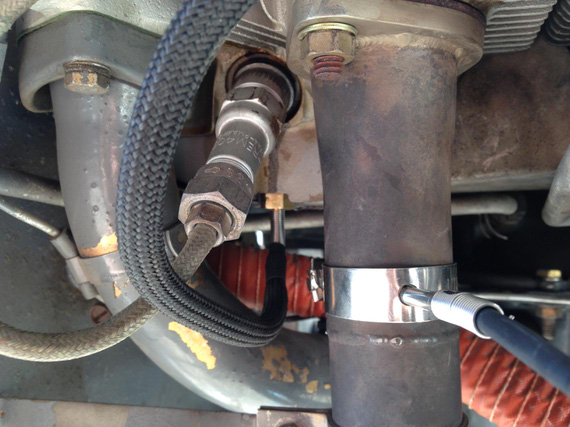
All sleeved
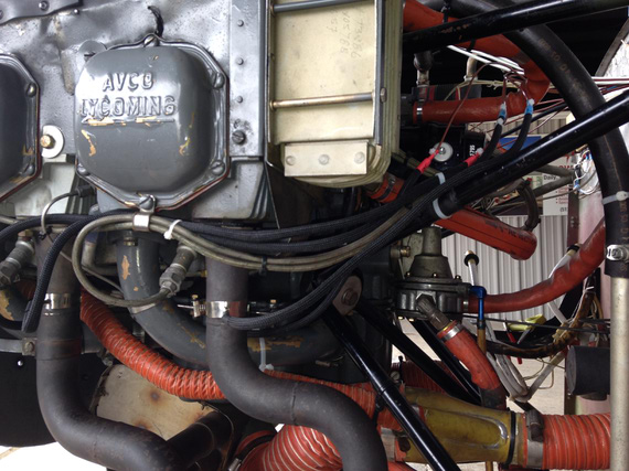
Sleeved and tucked away.
Sun was setting down at that time, and I called it a day.
Session 3
We replaced the alternator in the field, but I kept the cowl open to wire up the rest of the probes.
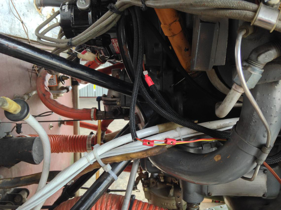
Installing and wiring more probes
I decided to install pressure transducers on the engine mount tubes using clamps, to keep them close to the engine outlets and hose lengths to the minimum. Consulted with EI again, and they said that's an okay idea.
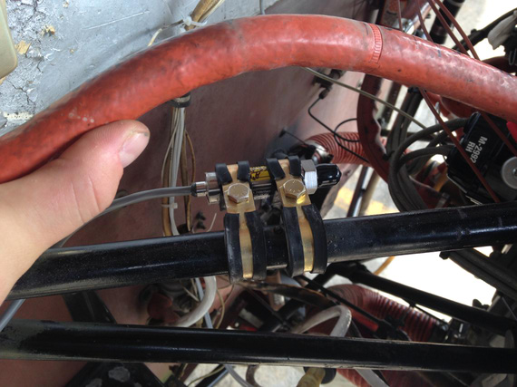
Oil pressure transducer
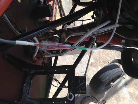
Oil pressure transducer wire-up
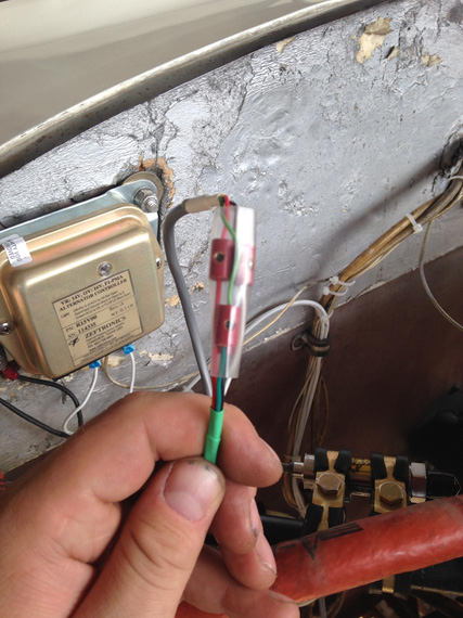
More wire-up
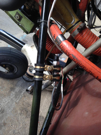
Fuel pressure transducer
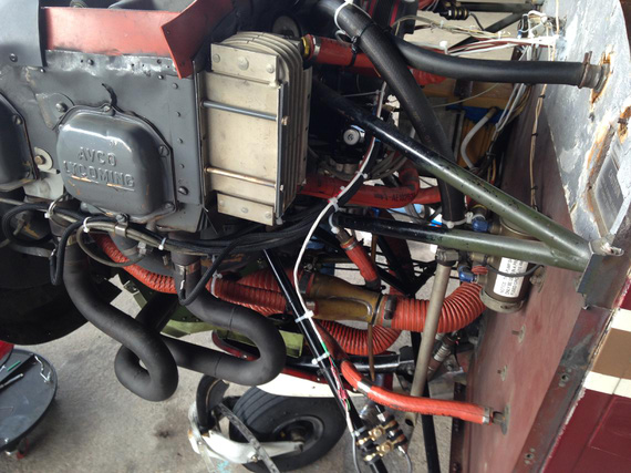
Fuel pressure transducer wire-up
That was it. I didn't install the fuel flow transducer yet.
Next, came closing that cowling, and a big break due to weather, travel, and life....
Session 4
This time it was a day to install the "aggregator box". All the probes feed into it, and there's a single wire that connects the box to the display of the engine monitor.
I didn't know what the exact length of the screws to mount it would be, so I decided to buy a bunch of different ones. Didn't have any way to measure the firewall thickness.
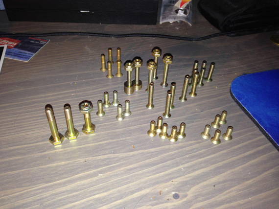
All that hardware
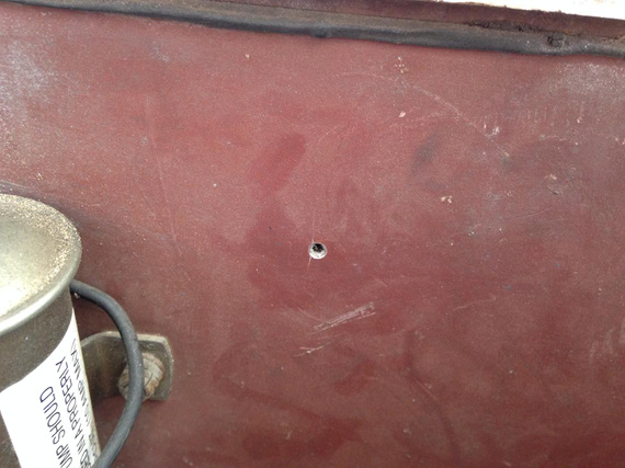
First hole in the firewall
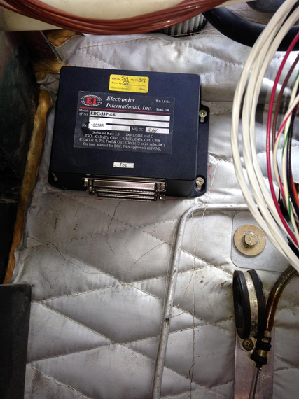
The "aggregator box" installed
That was a short day 'cause I had some things to take care of in the evening.
Session 5
So finally, it was time for a bunch of work behind the panel. Before then though, I decided to make a little panel insert that will hold the annunciator LEDs, the USB port, and the display dimmer.
As usual, played with the layout in Solid Works before I liked it. Decided on a 2 inch hole and fiddled with locations until I was happy. And then, used the final drawing as a template!
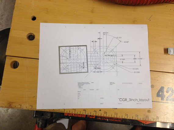
The layout
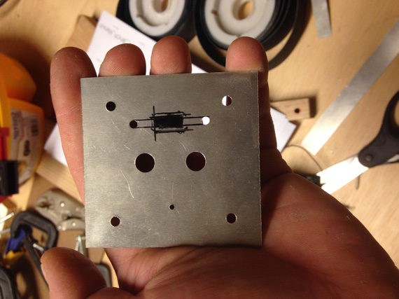
Cutting holes
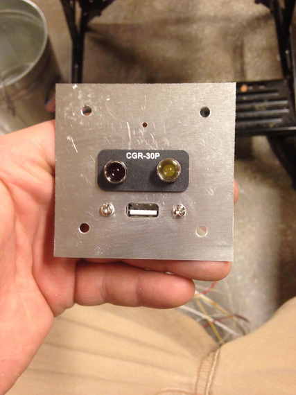
Test fit
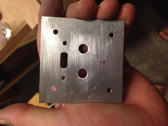
Cleaned up
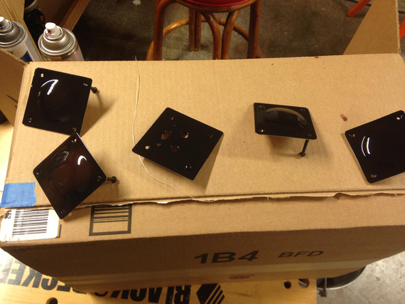
Painted. Also painted the panel covers
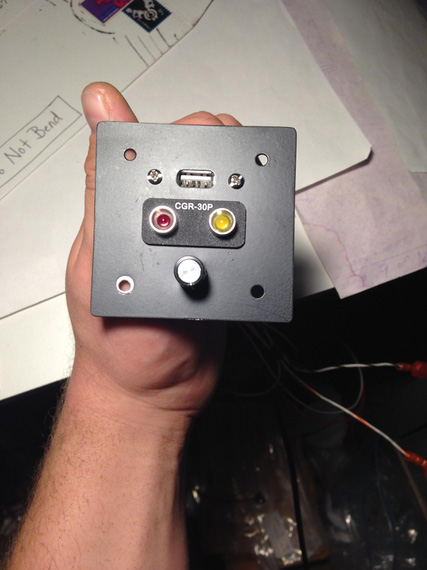
Done!
I also painted the panel covers that I took so long to figure out how to make.
Session 6
Finally, back to the hangar! This session took 2 days actually :). It was the time to install, wire up, re-position all the gauges on the panel, and such.
The old CHT, EGT and hobbs were to go. Clock was to be relocated to the position it's visible at (it was right under the panel eyebrow before). Davtron OAT/PALT/DALT/Volts gauge was to be relocated to another spot in the panel to free up space for CGR-30 auxiliary panel I made in the previous session. And, most of wireup had to be done. Harnesses connected to the box, ran to the display, and power.
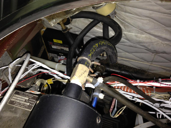
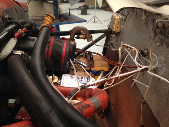
Box installed on the firewall, with harnesses coming in
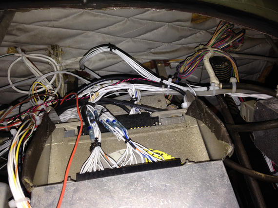
Behind the panel, sometime in the middle
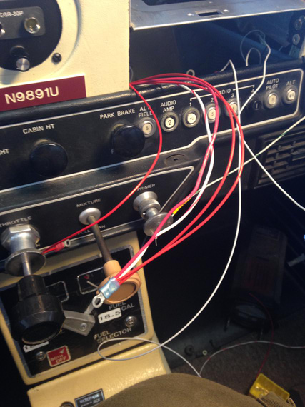
Ring terminals for power
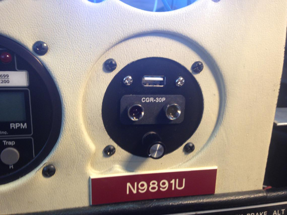
Auxiliary panel installed
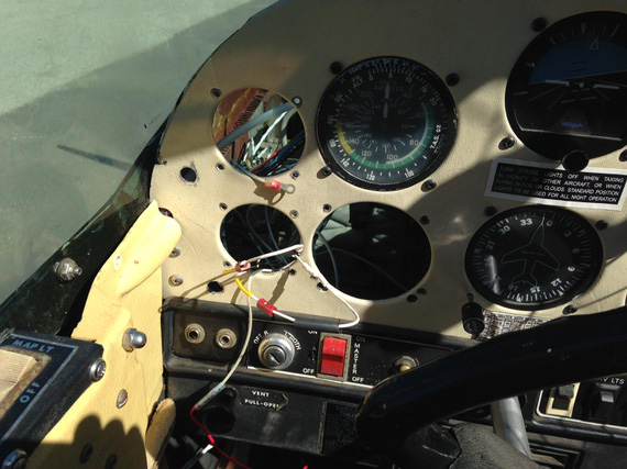
P-leads connected to mag inputs
And then, it was time for the first checkout.
I pull the plane out of the hangar, and hook the rest of things up with test leads.
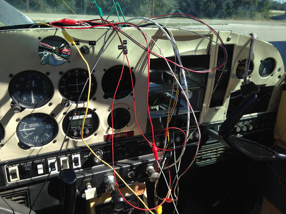
Test leads
Turn the enigne on, and observe!
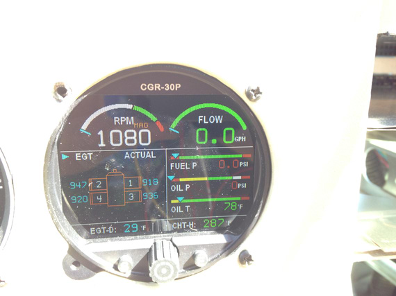
We're on! Oh, wait...
You see the problem? Yes, right mag is dead! Oh, and the old tach (I had one of those fancy Horizon P1000's that tells you if a mag is dead) is showing everything's okay. And, the engine starts doing this rattle sound, and quits. WTF?!
Thoughts about grounding something I shouldn't have grounded (ie, a plead) cross my mind. Then, thoughts about a loose screw somewhere next to the ignition switch crosses my mind.
I re-try. Same thing. Engine starts, runs a few seconds, and dies off. WHAAA??!
... I decide to go take a bathroom break. On the way back, another thought crosses my mind.... I get back, practically running, get into the plane - and sure enough! Fuel selector is "off". I switched it off the day before, before getting behind the panel. Just in case :) Phew.
The "right mag" problem doesn't go away though. I start diagnosing -- touching input wires to different pegs on the ignition key -- no matter which mag it is, "left" is okay and "right" is dead. Uneasy thoughts about a dead wire in the harness and having to undo the whole thing start crowding me... But, I decide to dig a bit deeper. Success!
Can you spot the problem?
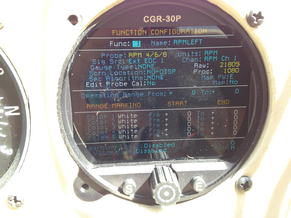
Left mag RPM raw signal value
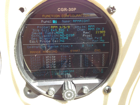
Right mag RPM raw signal value
Bingo! A call to EI, and a quick configuration update fixed that one.
Session 7
It was that time to go to Fletcher's and continue working on it there. Plus, my new wheelpants were ready!
Before I went though, I had to make one last missing bit. A bracket for the ammeter shunt. Did that at the home shop; and did it in a couple different widths to see which one fits better. That bracket was supposed to plug the hole left after old engine gauges removal, and hold the shunt.
By the way, I decided to wire the shunt into the battery leads. First of all, that's how Grummans are wired by default; and second, it actually shows you the actual discharge when you're on battery -- a good thing! It doesn't show the true load when charging the battery though -- just the charge current. That's okay though, as long as charge current remains positive I know my alt is okay.
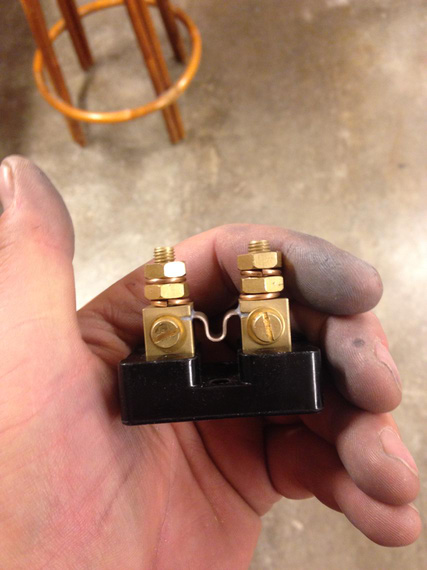
The shunt
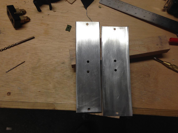
Two shunt plates
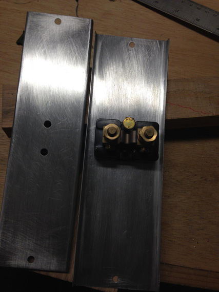
With the shunt
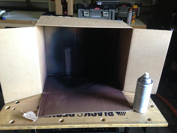
My makeshift paintbooth for painting these little boys
All that bending, sanding, filing, and drilling took about a couple hours in the shop.
Session 8
Onward - to Fletcher's!
We've measured lengths for all the new hoses; and decided to change all of them -- mine were manufactured 15 years ago. Also, found a small oil cooler leak, and decided to replace that bad boy. Oh, and I was finishing up behind the panel while David's guys were working on fitting and trimming my wheelpants.
I took out all the gauges, unwired everything that was to be removed, and installed the shunt... Then, it was time to call that a day since Clayton was supposed to fly me back, and I didn't want to make him go back after dark.
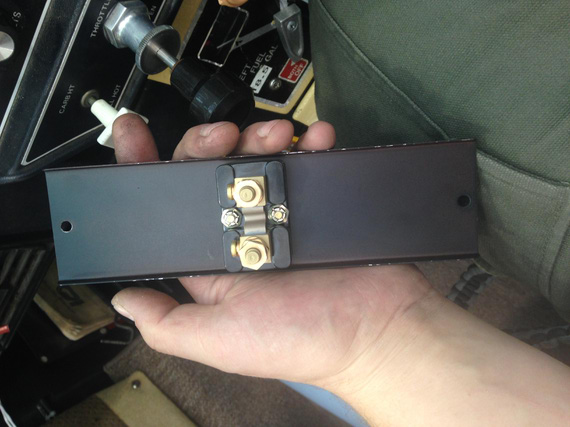
Shunt attached to the bracket
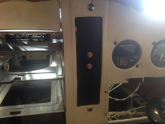
Installed. The bracket replaced old engine gauges.
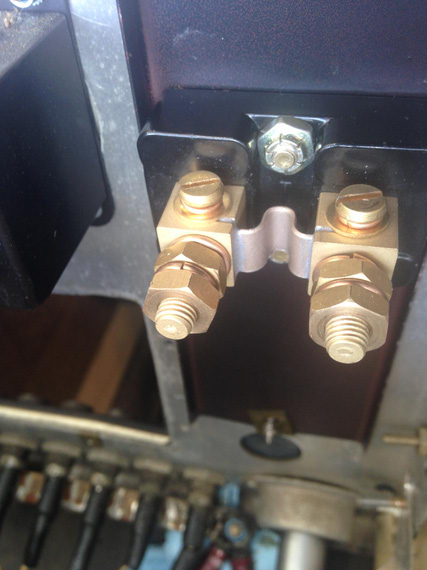
Shot from behind the panel
Session 9
I drove up to Fletcher's to finish up some more work behind the panel.
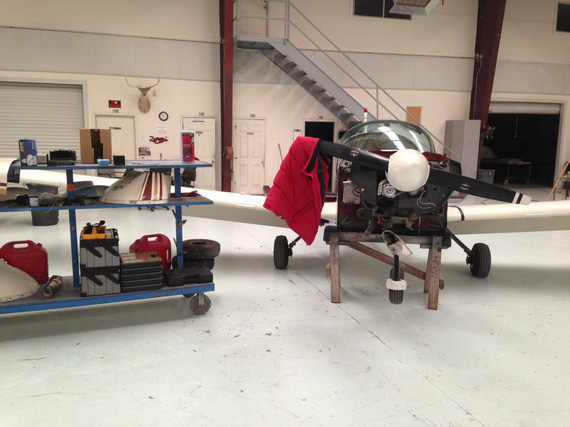
Another day
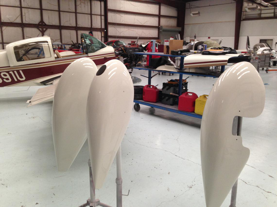
My new wheelpants, all painted!
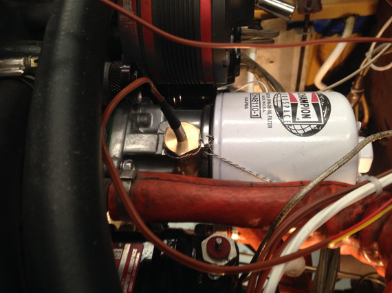
Oil temp probe installed and safetied
Final wireup
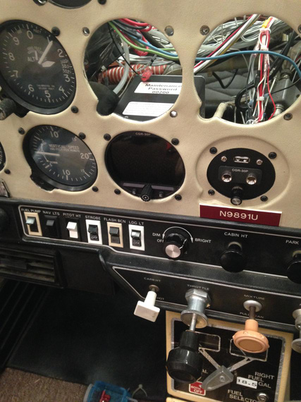
Display installed on it's final place
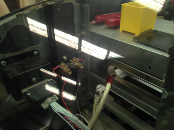
Starting to wire up the shunt
When trying to do the shunt, I realized that I didn't have the right size terminals, and the big enough crimper... Oh well, left that over to another day
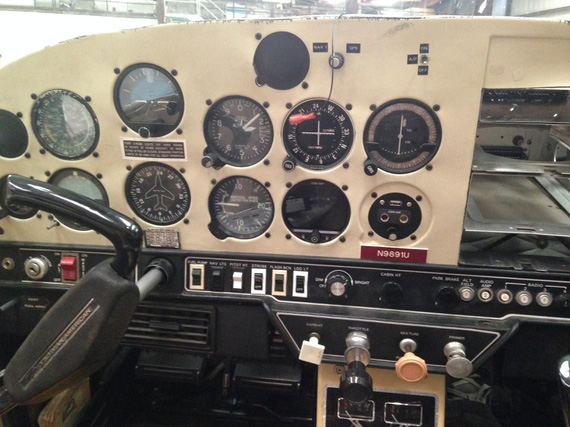
Final panel, with CGR and all the holes plugged
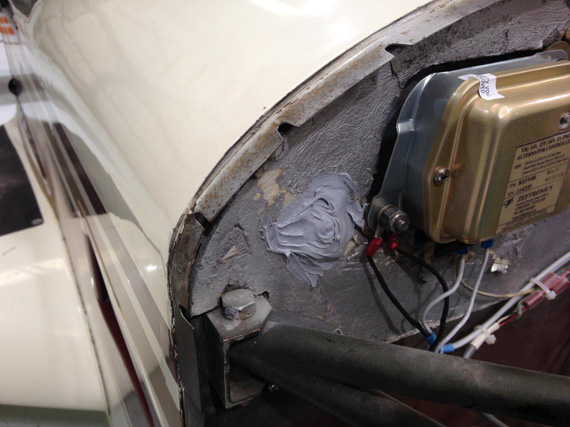
All holes left after oil and fuel lines removal patched
Also that day, I felt a blast and wanted to do more -- so decided to do the last finishing touch and clean up the oxidation off of my mixture knob. Acetone, baby!
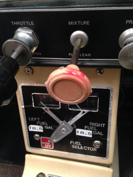
Before
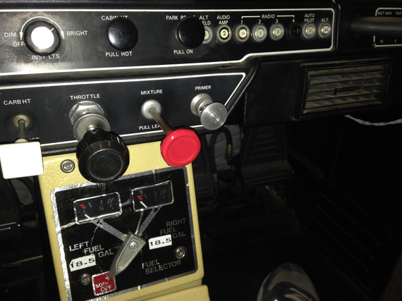
After
Good day!
Session 10
Last one! I arrived about a week later, to find the pants installed, oil cooler installed, and all hoses hooked up. John also hooked up the fuel flow transducer. And I made sure to have that crimper and right size ring terminals.
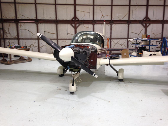
Wheelpants!!!
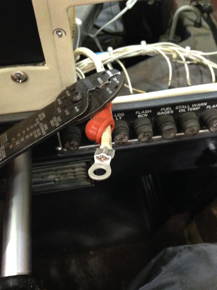
Battery wire ring terminal crimp
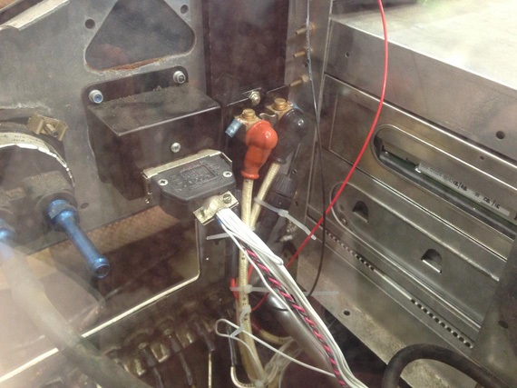
Shunt wired up
After that, we decided to temporarily hook up the cowling, and do the weight and balance, the right way. Too many changes. New oil cooler, new wheelpants, new gauge.. Plus, I know this particular airplane was never weighted at the factory, so why not.
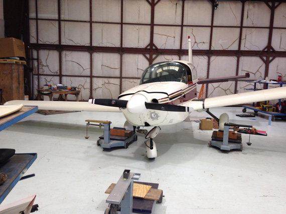
Speak of unusual attitudes! One wheel on the scales.
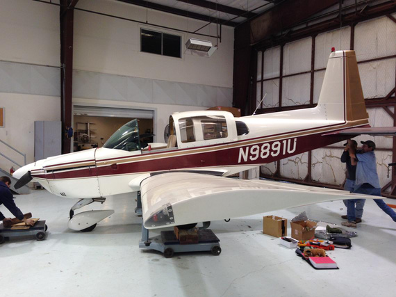
And another. "Pull up, Jimmy!"
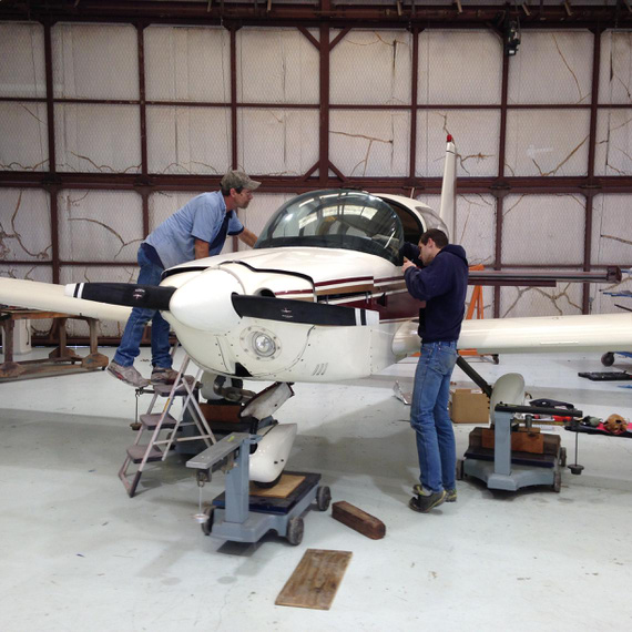
On scales. Leveling.
... and then, it was the moment of truth, sort of. Final checkup. Rolled her out of the shop, fired up, and...
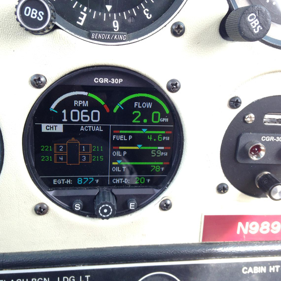
All green!
Shutdown.. checked all hoses -- a little drop of the oil on the oil cooler inlet. John said there was some oil in the hose, to wipe out, and try again.
Did just that. Fired up, and.. fuel pressure shows 0. "Oh shit!"... You guessed, right? Fuel switched off, again! Damn, that thing actually works!
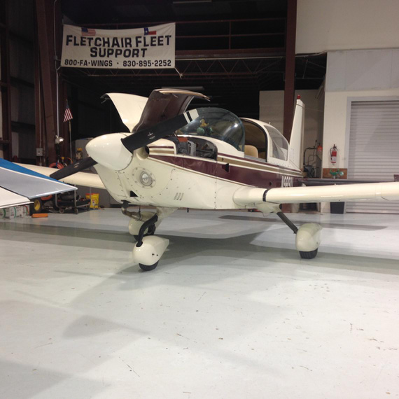
All done.
And so
I suppose I have to give some final thoughts.
Here's what I like about the gauge:
- Compact, takes only one hole.
- Not square! I hate square display engine analyzers. Don't fit right into the steam panels.
- Good documentation. Sometimes missing details like torques, but otherwise good.
- Great packaging and wiring harness pre-setup! Each wire came with a little sleeve identifying it. Didn't ever need to look at the harnesses diagram for wire-up.
- Great software and setup.
- Great support.
Here's what I didn't like:
- Single-stranded, unprotected wires for the probes
- The fact that I had to run the harness into the box, and then connect the box to the display. In my case, it made the wires longer, since they had to run from the in-hole in the middle of the firewall to the side where the box was mounted. Would've been easier to go straight to the display. I discussed this with EI actually; and they said that that was a long debated issue -- and they opted for the box, since that setup helps guys that have their engines far from panels (twins for example). I understand this rationale.
- #8 mounting holes on the "aggregator box" with countersunk screws. Would've been much easier if they had a #10 holes for AN3 bolts.
- Quality of OLP-1 barrel connectors. Very sharp plastic edges. I wasn't comfortable tying them to the wires just like that and had to hand-deburr all of them.
Overall, I love it. Great gauge, and I will be putting that on the Skybolt! :)
If it doesn't work, rename it. If that doesn't help, the new name isn't long enough.
Up ↑
Rack-o-Ribs
lotsa hours
| On: | Nov 23, 2014 |
| In: | [Skybolt] Wings |
| Tags: | CAD, lower wings, ailerons, ribs |
No posts about the Skybolt doesn't mean that there was nothing done :). Yessir!
I was redrawing pretty much everything I did in the first few months of modeling the lower wing; and that ate up a bunch of time and didn't actually produce anything to show. But damn, did it suck up time!
I ended up re-doing:
- Spars
- All ribs
- Full wing assembly (now it's clean and easy to tweak)
- A lot of compression plates
- Complete aileron assembly
Especially with ribs, the problem was that I did them while learning SolidWorks -- which led me to sketching them in AutoCad first (I used to hate doing curves in SWX.. now I hate Autocad, but that's another story :)). That made them virtually un-tweakable; and "tweaking" the verticals, which I had to do after confirming drag wire interference, proved to be virtually impossible.
So, I decided to clean it all up. Oh yeah, and I have moved that interfering vertical.
The brand-spanking new set of ribs:
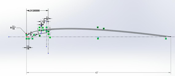
Master sketch, off of which everything else was derived

Butt Wing Rib

Typical Wing Rib

One of the many sketches that go into a rib
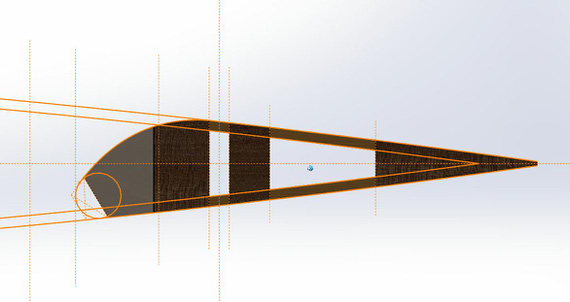
Aileron rib

Rrriiibbzzz!! Oh, wait...
And then, only then, I could go on to finishing the tip rib and the aileron tip rib.
For tip rib, I used the positioned tip bow to project the cuts onto the surface of the nose block. I'll explain this technique in a bit with aileron as illustration.

Tip rib, with all the cuts that will match the bow perfectly

Tip, and other ribs, on the spars, and tip bow
And then there's the aileron, it's bow, and tip rib.
I started with a "placeholder" that was the inboard (full size) butt rib. Then, using the tip bow, I drew a couple of "guide curves" and projected it on a couple planes, corresponding to ribs, giving me two different profiles.
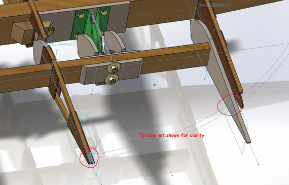
Projections, and helpers
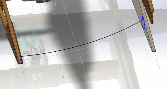
Guide curve and loft profile
Then, I set up my loft, and voila!
After that, I drew the butt rib. In the previous post, I said that it is supposed to be a touch larger profile than the tip wing rib; but that ended up not being the case -- in fact, it's a touch smaller and somewhat "hides" in the aileron well area. I decided not to mess with that...
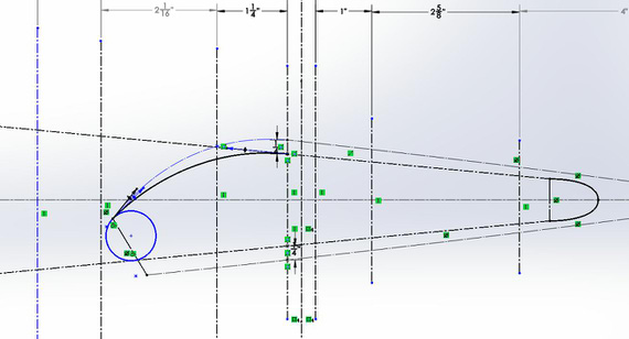
Tip rib sketch, derived from the "regular" rib, and the tip bow "intersecting" with it
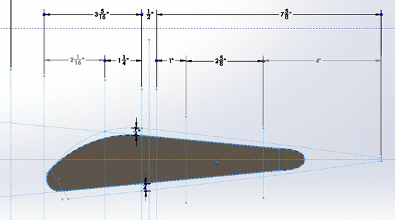
Aileron tip rib model
And here it is, in all it's glory, with the bow, tip rib, with everything matching perfectly. Note how the tip bow of the aileron changes shape along it's length -- that will be a hard one to hand-shape when making it...
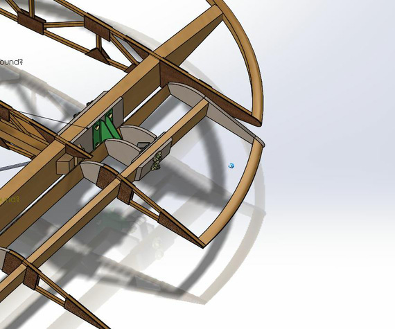
Aileron on the wing
Always remember you fly an airplane with your head, not your hands.
Up ↑
Strobe Shields for Cheetah
... fun with stretcher
| On: | Oct 24, 2014 |
| In: | [Misc] Cheetah |
| Tags: | 9891U, mechanicing, sheet metal |
No Skybolt news, you say?
Well, with dead alternator, tons of work, and unfinished install of a gauge that is supposed to keep you informed about your engine, not much time for the Bolt.
Oh well.
I love to fly at night. It's just something out of a different world, something... else.
There are a few things that are extremely important at night. Most importantly, the old "See and be seen" rule.
To be seen, you need blinking lights on your airplane, nav lights, ideally a landing light, and such.
To see, you need to retain your night vision. That means, no bright white or any color light besides something like red or blue. Otherwise, your eyes readjust for "daylight", and you are at good odds of not seeing other blinking lights... like the ones on an airplane you might fly into!
You see, I don't have strobe shields on my plane. Take a look at the picture below, and imagine you sitting in the cabin.
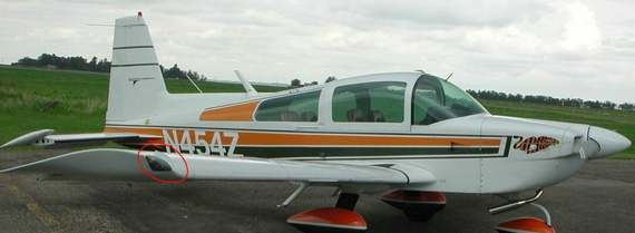
Strobe Shields on a Grumman
You see that vertical little metal "fin" I circled? That's what blocks you from seeing the strobe - a bright flashing white light. If that metal fin is not there, you basically get blinded every second or so.
It's so bad I ended up flying with strobes turned off a couple times I was up after dark. I figured, just one beacon on the tail and no strobes is better than a blind pilot.
And especially now, when the weather in Texas is so nice and night flying is just calling and calling and calling, that became a priority project.
So, on to it!
Those shields go under the wing tip light cluster lens, and the spot they're supposed to go into is curved. Shields themselves are nothing but a curved L - angle out of aluminum.
So, I needed a stretcher.
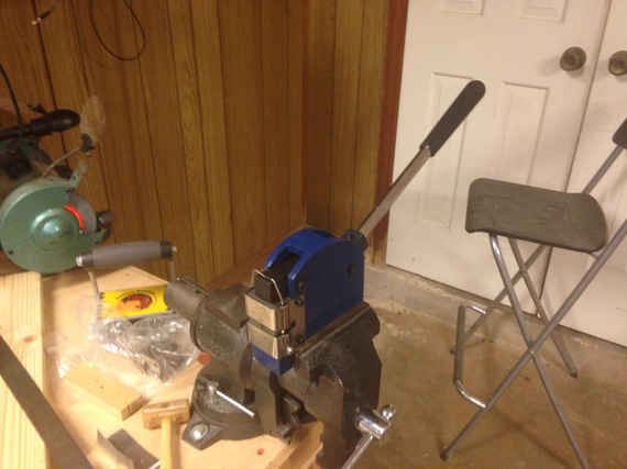
The Stretcher
Prepared one of the wingtips:
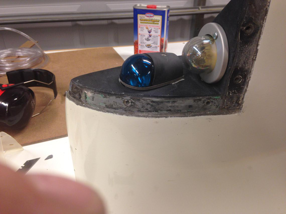
Wingtip light cluster with the spot where the shield goes cleaned up.
First, I decided to make a test piece to get some practice. Never used a stretcher before.
We start with a simple L-angle. I used 6061-T4, 0.025 thick.
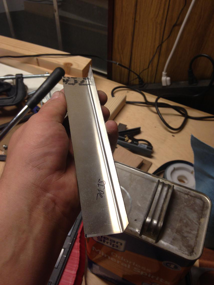
Simple angle
And then, stretch-check-stretch-check... Not bad at all. Just takes time.
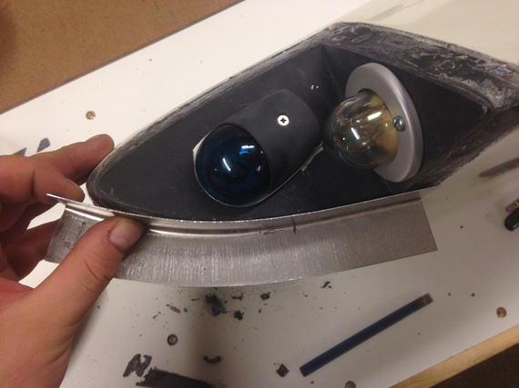
Stretching
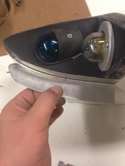
Close enough for a prototype.
You can see on the pictures that the stretcher leaves pretty deep "scratches". On the prototype, I tried sanding them out -- only to get my metal turn paper thin.
On the real one, I decided to fill them up with Bondo.
So, bought some, and made myself a pattern too -- which I printed full size.
To do that, asked Adam, the guy who bought my 28797's share (thanks again, man!) to take some pictures of strobe shield on his Tiger.
And then, just drew around it in Solid Works. Turned out nice.
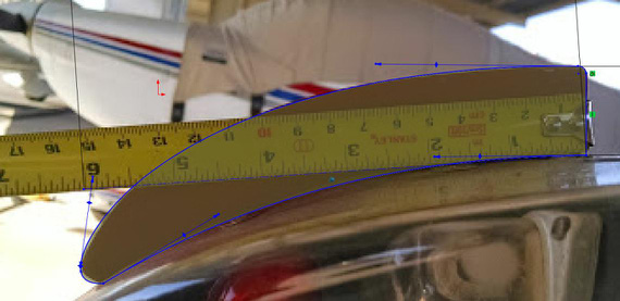
Sketching around the photo in SWX.
Note the tape measure above -- I first drew a line 6 inches long and scaled the photo until that line matched 6 inches on the tape measure. This way I ensured proper scale.
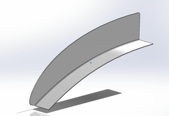
SolidWorks part for the Strobe Shield
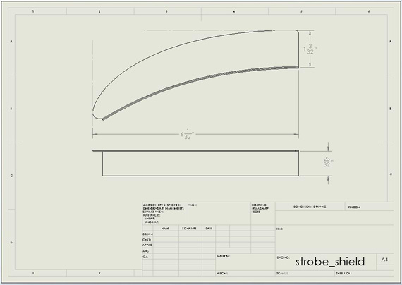
Drawing of the part for the patterns.
So with those patterns printed out, I went to town.
First thing I noticed is that curvature on the wingtip I was working on doesn't match the pattern :). Of course. They're all different (and by the way, on the other wingtip it matched perfectly. Go figure.). I wanted the pattern to primarily get the general shape right.
So, here I am stretching my L shaped angle, and... SNAP!
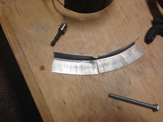
:(
So now, bend another L angle, deburr, clean up, size... sigh.. I went much much slower...
I think, getting it perfect took around 3 hours of careful work. That curve gets aggressive towards the end. And, when I was almost done.. snap! I tore it up again, this time the very tip.
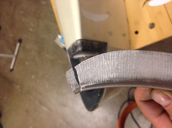
Damn!
Luckily, it actually still was long enough (I started with a piece longer than necessary), so I was able to get away with this tear. Phew.
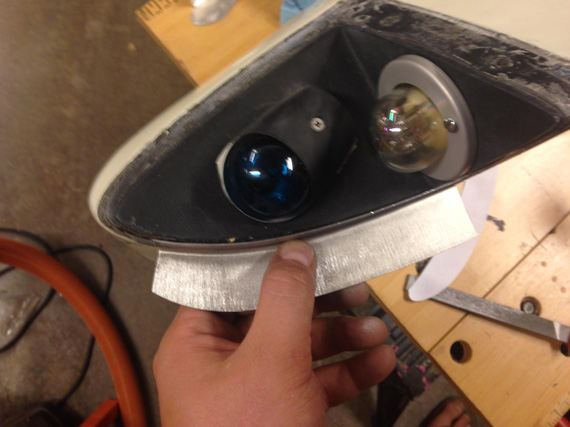
Perfect fit!
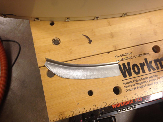
Cut to about the right size
Next, came a lot of sanding, filing, and emery-clothing to get it to the right shape. And then, the holes.
Those had to be duplicated and match up with the existing holes in the wingtip, so I made a simple hole duplicator. No, I'm not paying 10 bucks for that thing!
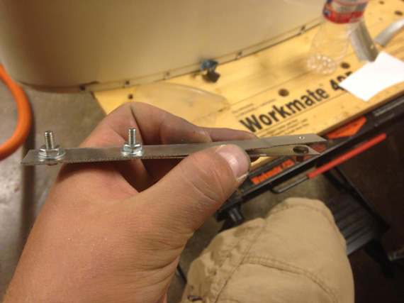
Homemade Hole Duplicator
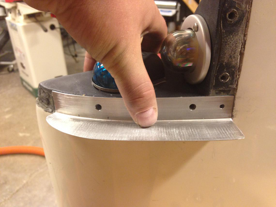
And, we have the holes.
Finally, I filled all the scratch marks with Bondo, sanded it down, and called it a nite. I think it was around 3 am then :).
Next day, the other wingtip.
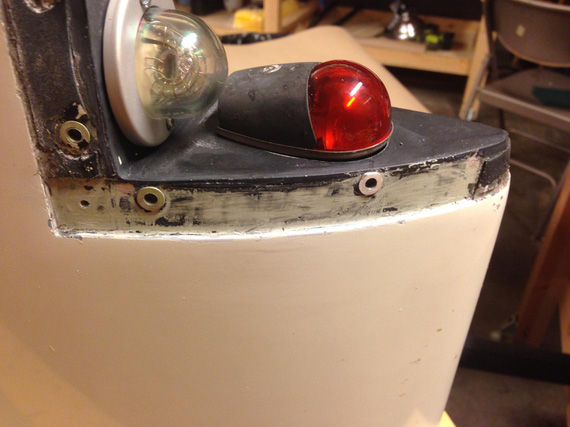
Prep
Notice that this one has rivnuts and not just holes. I now have a theory why this plane is missing strobe shields.
I think the guy who tore all the threads in the fiberglass wingtip and installed those rivnuts (remember, the other one doesn't have them?), was too lazy and didn't want to tweak the holes in the strobe shields to match with the rivnuts. That's my guess.
Initially, I thought about making oversized holes in the shield, but that would put one of them too close to the edge. Then, I tried filing the rivnut down a bit, but decided that I'm not gaining much there, and that notching the strobe shield base would be best. That's what I ended up doing.
I made just the first notch, and to stretching it was!
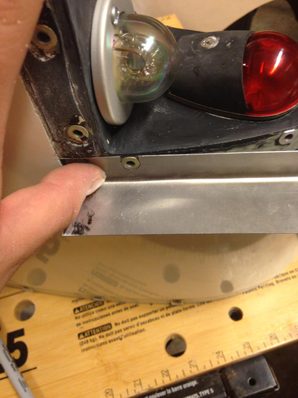
First Notch
When it was close to the other rivnut, I notched area around it.
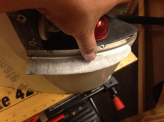
Secont Notch - close!
They came out perfect.
And then, tons of filing, shaping, sanding, Bondoing, sanding, washing, and...
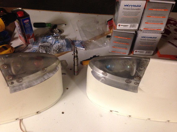
All done!
They're not quite complete yet. I'll have to clean up the rest of black tape from under the wingtip lenses and replace them with new ones, but that'll come after painting the shields. I'll ask Dave Fletcher to paint them into the same Imron he's gonna use for the (now soon to come) wheelpants.
And you know what.. that was fun!
If God had intended man to fly he would have given him enough money for a Bonanza.
© Copyright "79FT". All rights reserved. Feel free to cite, but link back to the pages cited.
This website only shows how I did things in my various projects. These pages are for information and personal entertainment only and not to be construed as the only way, or even the perceived correct way of doing things. You are responsible for your own safety and techniques.