[79FT]: Building Things |
 |
Brakes and Wheels
fixin' and bleedin'
| On: | Nov 04, 2019 |
| In: | [Chickenhouse Charger] Electrical Rebuild |
| Time logged: | 23.1 |
| Tags: | 6781G, MA5 Charger, Annual, brakes, wheels |
So this one turned into a month long project, give or take. Sure, sure, I was doing other things, too: last one of which was completed October 9th... after which I was finishing this one exclusively, pretty much.
Damn. One month to finish putting the brakes together. Granted, I had a hiatus for a week and a half, dealing with fixing up bad (non-aircraft) plumbing and cutting (non-aircraft-grade) trees.
Regardless... Shall we?
...
After having finished making the new brake line, I naturally wanted to install it and call brakes done.
Some of the disassembly work documented here actually happened prior to the new line being bent up, but hey. Putting it all in one place makes for a better narrative in one context.
First, the Calipers
... one of which was cracked due to someone having overtightened the bleeder adapter. Oh well.
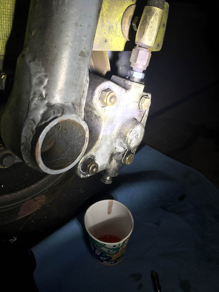
Drain
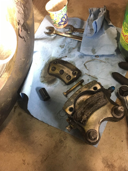
... and pull
Brake pads were soaked in brake fluid. For that matter, the disk was covered in brake fluid that hardened to molasses-like consistency (which mineral milspec fluid does, apparently).
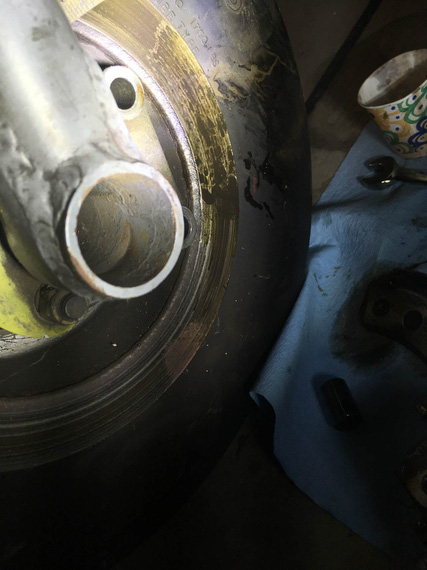
Ugly smudge
Intermission. By the way, it seems that this smudge didn't come from the dripping bleeder, but rather, judging by how the pads were soaked, from under the brake piston. Probably the o-ring was bust, and it was weeping from between the caliper and the piston. It seems that it had been a feature of the plane for a while.
Jumping a bit ahead of myself, on the other side, I discovered the brake disk somewhat dirty with oil - crankcase breather hoses are routed into the _left_ side wheelpant and terminate near the disk - clearly, spraying a bit of oil on and around it. You'll see those hoses on the pics of the left wheel below.
I think Remo's idea was to prevent oil on the belly from the breather. My friend's Ben contention was, this was a brake lock-up prevention measure; and when he brought it up, I immediately realized... leaking piston on the _right_ caliper was a lock-up prevention measure as well - to make sure both brakes are equally slippery - right one with brake fluid, left one with motor oil... At any rate,..
I will admit, this was my first caliper job ever, and anchor pins presented a bit of a problem. They're press fit in the caliper, and I didn't have an arbor press. Well, I used an old 1/4 nut that I banged on (gently!), and finished with a drift punch....
Tappy-tap-tap!
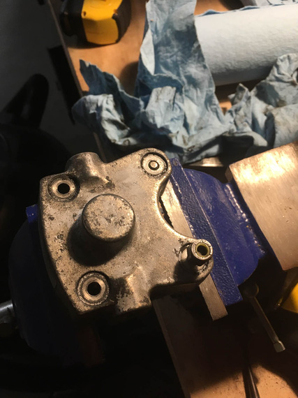
Tapping out the pins (aka anchor bolts)
With the caliper put apart, I tossed the old body, and took maroon scotch-brite to the rest of the pieces to clean them up.
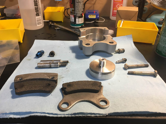
Cleaning up the parts
Now, I tried tapping the anchor pins back in, but was too afraid to mess them up. Finally, that was an excuse to go get me an arbor press!
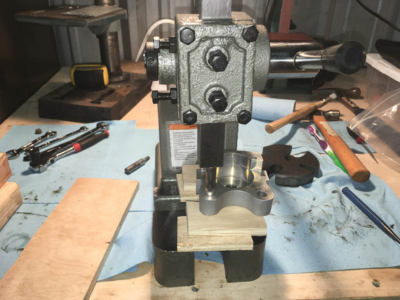
Pressing the pins back in
One final bit was to put the nuts back on.
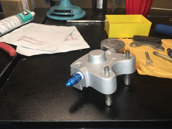
Ready for nuts
Question: how many wrenches does it take to put on an aircraft grade nut properly? Answer: three.
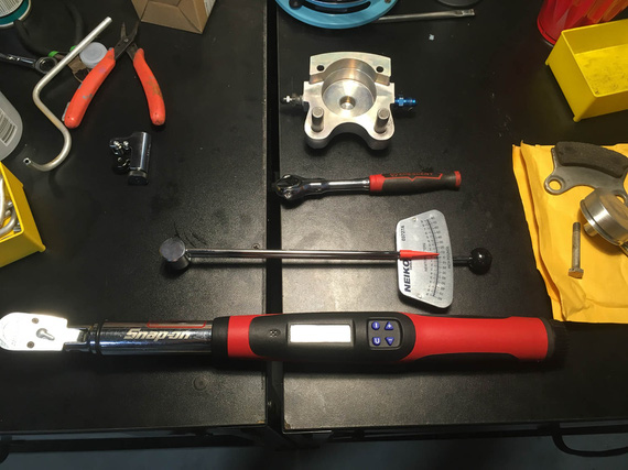
Wrenches!
Answer: three. Ratchet to work the nut before it's torqued. Small torque wrench to determine the free torque. Large torque wrench to torque to spec.
I pulled off the other caliper, and cleaned it up, too.
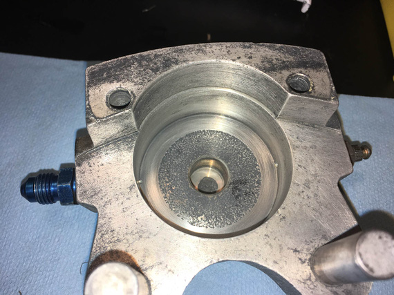
Left caliper, cleaned
Put in new piston o-rings, cleaned up AN flare adapters, put the calipers back together, and put them away.
Next step was,
The Parking Brake Valve
That little doodad was leaking for a long time, too. It seemed it was leaking from the little cam arm that rotates, but I wasn't sure, so I decided to put it apart and rebuild it completely, too.
It's under the passenger's seat on the Charger.
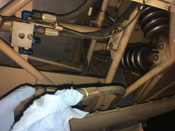
Pulled it off
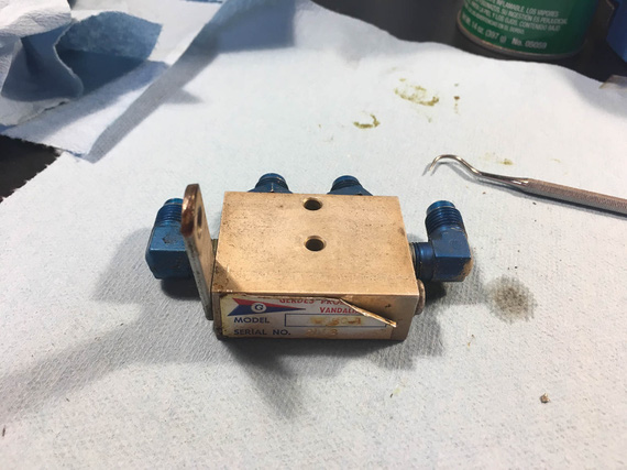
On the bench
First, I pulled the "cam arm" out - the little arm pivots, and pushes valves open (or lets them close) inside the box.
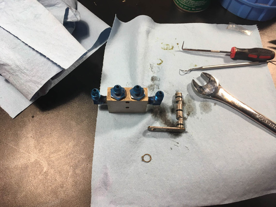
Cam actuating arm
O-rings were in reasonable shape, but looked a bit.. old. I decided to change them and disassemble the rest of the contraption, to change all the other o-rings in it.
Now, the middle two "straight" fittings are straight threads and o-rings under them. No problems there.
The two 90 degree elbows on the sides are NPT. One came out just fine. The other... Well, the other decided to leave a chunk of itself inside the valve body...
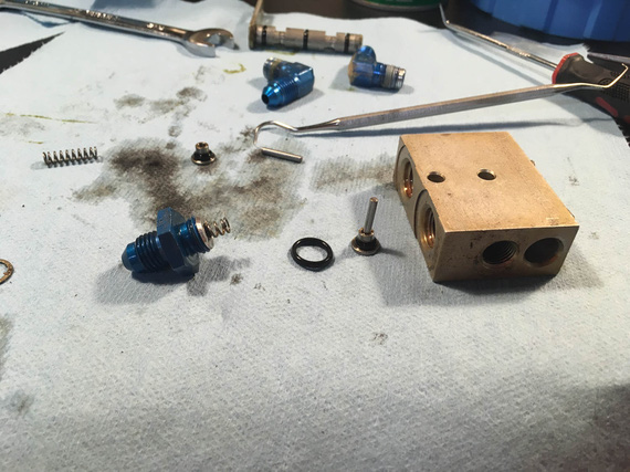
Bits and pieces - valves, springs, and actuator plungers
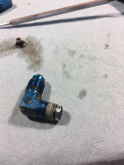
Busted elbow
You can see the chunk of the male thread galled and stuck in the female NPT hole of the body.
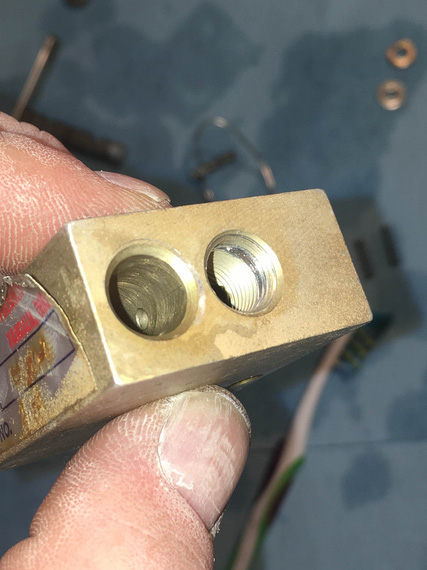
Chunk of thread
Damn damn damn! I need a new parking brake valve now?
That new valve is how much (search.. search.. six hundred and sixty five!?!?!?!?! $#*@(&(2@@#!). No way I'm paying that.
There are alternatives. Cheapest one is like what, hundred fifty bucks; and I'll have to work around it's plumbing (which is different than mine); and the "direct fit" "homebuilt" cheapest one is over $300? No way. No way in hell until I try to fix this.
What is the hole? 1/8 NPT? McMaster sells taps for $25, two new fittings are what... under $30, and a handful of o-rings, which of course I didn't have (I have a bunch of o-rings in a ton of sizes for fuel applications, but not for brake applications).
We'll try to re-tap that hole; hopefully braking the piece of the thread left in there by the fitting while keeping the female thread intact...
... the tap and the o-rings got delivered a few days later. Made myself some nice soft jaws for the vice to hold the thing without scratching it.
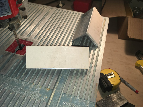
Soft jaws
That's aluminum angle and leather.
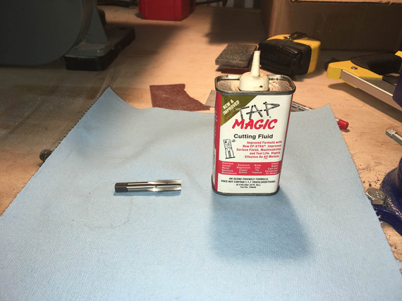
Weapons ready!
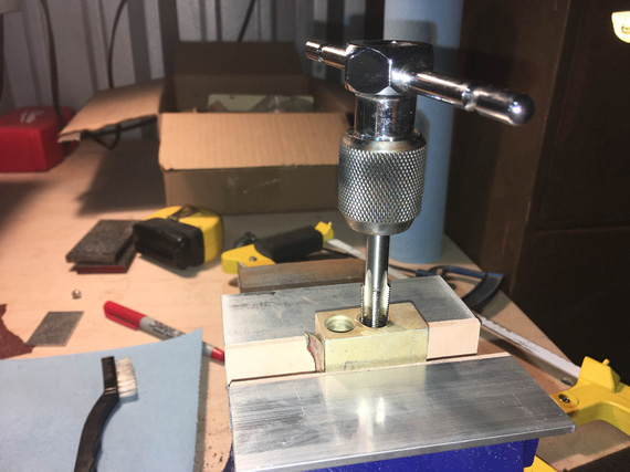
Tap, tap, tap (not that kind of tap!)
Slowly, slowly and gently, breaking the chip every 1/4 turn and adding cutting fluid. It worked out great! The hole was deeper than needed, so I tapped the threads a bit deeper, arguing that if the female portion of the threads got chewed up a bit, I'd put a fresh surface on them too.
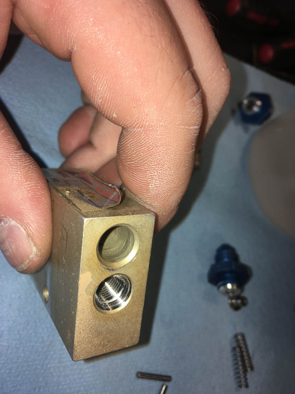
Done!
Well, we'll have to wait to see how well this works out. If it doesn't leak, I just saved me a boat-ton of money.
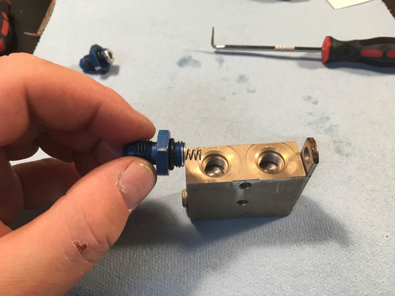
Putting it back together
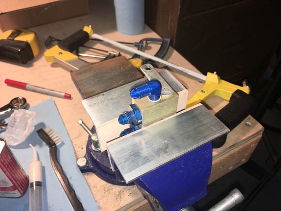
All done
New o-rings, new elbow fittings, re-tapped hole. Threads on the busted hole felt good, no hesitation and "catching". We'll see how that works out...
Next,
The Pads
Pads on the right brake (the one with leaking piston o-ring and busted caliper) were soaked in brake fluid. Cleveland says contaminated pads are a cause for replacement, so I decided to do it, since I was already in there. Besides, excuse for another tool - this time, the brake rivet set!
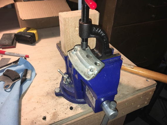
Punching old rivets out
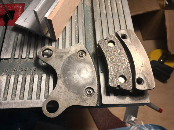
... and putting new ones in
And with that, the last bit before we could put everything back together was,
The Wheels
Again, since I was already there, I decided to do the wheels at this time too - re-pack the bearings, that is, and give the disk contaminated with brake fluid a real good cleaning.
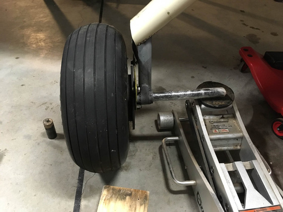
Jacking the plane
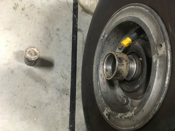
The axle nut comes off with finger pressure
I admit - I made a mistake here. I did not remember what kind of resistance I felt when spinning the wheel on the axle before I took off the nut and took everything apart. It would've been important, especially since this was my first time doing these wheels, and wheels in general....
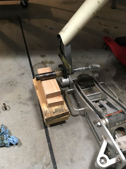
Temp "wheel"
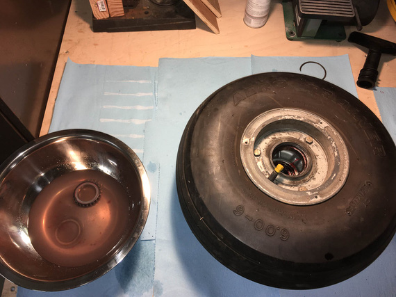
Cleaning bearings
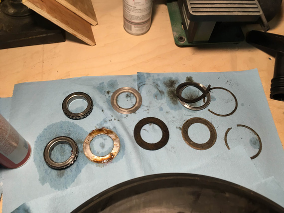
All the grease seals (and bearings)
Crap! What, the felt seal is bust!?.. Looks like it is. Okay, not finishing this part quickly (because of yet again, another "order parts / wait" cycle).
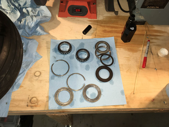
Flushed, and drying
Do you see the other mistake I made? Yep. I mixed up the bearings ("front" and "back"). Bearings should always stay with their races...
Oh well. After some research, seems that the worst that will happen is wear will get accelerated.. since the bearings and races looked squeaky clean, I decided to keep them as is.. for now. And just Hail Mary the position (since I have a 50% chance of getting it right :)).
I decided to replace all the felts because I was changing grease from I didn't know what kind but likely red Mobil grease to Aeroshell 22.
Ironically, I apparently didn't take a single picture of the bearings being greased - probably because my hands were too greasy doing them :). Oh well.
The new felts came, and got coated in grease.
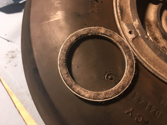
One of new felts
And, I put the wheel back together. And then... And then, I couldn't tighten it back right. I have to align the hole in the axle nut for the cotter pin... I could either get it under-tight (with perceptible play in the bearings - not good), or a bit over-tight (so that the wheel will spin, but with some measure of resistance). Remember, I said that my mistake number one was not checking how freely this wheel spun prior to pulling it off? Now, I was paying for it.
I tried flipping the bearings around (because I didn't note their original positions), thinking that maybe that will help. Nope. No change at all.
Oh well. I couldn't do anything about that at that point, so decided to settle on "a bit tighter" option.
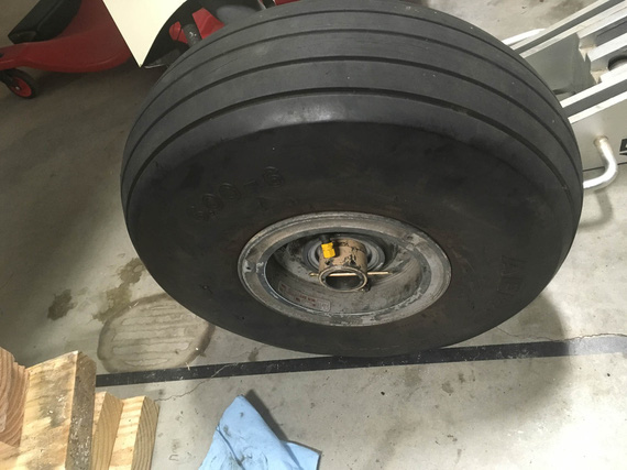
Cotter pin
With the other wheel, things went much smoother (the second time you do the job, it takes you 10% of time it took you to do it the first time, right? :) ). It came off, was cleaned, and got back on, with new felts and bearings in the original positions. Nut got tightened to super tight, loosened, and tightened to finger tight - and the wheel was perfect. No play, and no "drag".
Le double sigh.
So finally, it was the time to put things back together!
Putting the Brakes Back On
That was almost pleasant, after all the mess-aroundary with bearings. I cleaned up the pins' glide bushings, and lubed them with Dri-Slide (graphite + moly) lube Parker recommends.
And then... Calipers on, slide the bolts in, torque.
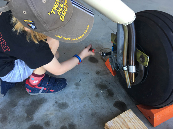
Putting calipers back on
Even a child could do it! By the way, that's the left wheel - remember I was mentioning the breather hoses routed to that wheel? There they are, in their awesome oil-spraying glory...
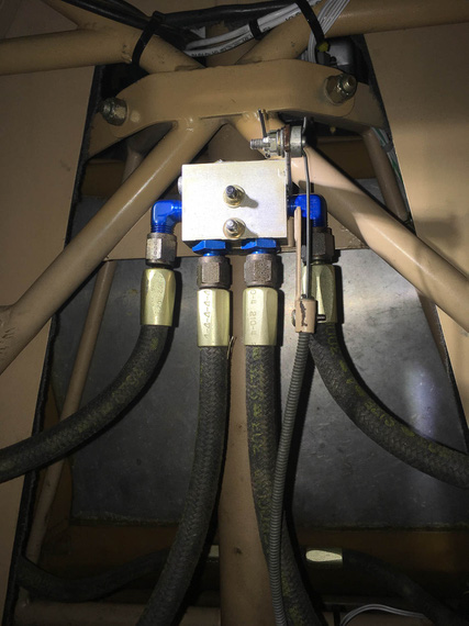
Parking brake back on
Put the parking brake back on.
Phew. Now, finally, we can bleed and test!
Bleeding
Now, there are two approaches to bleeding brakes - either bottom up (push fluid up thru the bleeder valves), or top down (sit in the plane and squeeze the pedals while the other guy opens and closes the bleeder). Bottom up is inherently simpler.
Some time ago, my buddy Dick was showing off his fancy bleeder he got from ATS.
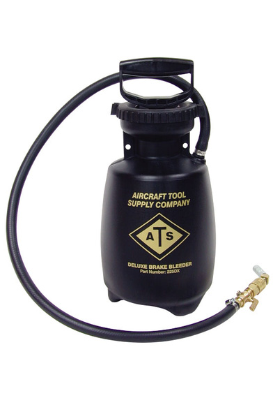
ATS Brake bleeder
Hmmm.. What is that reminding me of? Aha! Bug sprayer! That's right
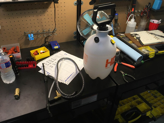
Bug sprayer
Now, a few minor modifications, and...
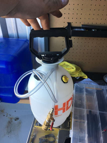
DIY brake bleeder
Pump it with air, open the valve, and the brake fluid gets pushed out thru the line that attaches to the bleeder valve on the caliper. Child's play.
For bleeding, I dragged my good friend Nick S. to give me a helping hand. I could've done this by myself, but having someone watching over the "other end" (it either being the end that pushes the fluid in, or the end out of which the fluid comes out) makes the job much more pleasant.
Now, the way brakes are plumbed on the Charger is, each side goes from it's caliper up the gear leg to the parking brake valve, then to the Master Cylinder, and from there both Master Cylinders are plumbed into a tee, from which the single line (the one I was re-making earlier) goes to the reservoir on the firewall.
We decided to bleed each side up to the tee first - to minimize the amount of air ending in the "common" line between the tee and the firewall. After bleeding each side up to the tee, we'd attach the "common" line and bleed each side up to the reservoir, letting at least a cup of fluid to flow thru, ensuring that we push all the air out.
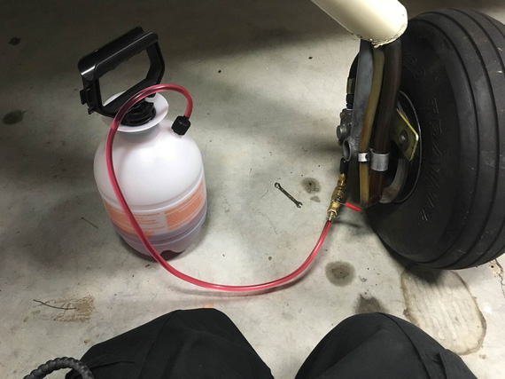
The setup
The plan went without a hitch, aside from the fact that I initially forgot to open the parking brake, and was trying to figure out why the hell the fluid won't flow. Hehe. Nick called it, too!
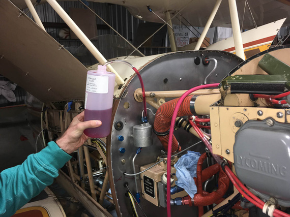
Nick holding the fluid line from reservoir
Finally, the moment of truth. The brakes were firm and nice, held well, and no leaks nowhere! Now, I need to double-check this - next time I'm in the hangar for a good few hours, I'll set the parking brake to keep the pressure in lines, and see what happens - but initially, everything held just fine! Phew.
So finally, the last bit was left.
Finishing the New Line Install
Now, the new line was finally in place, and all that was left was to install some ADELs to hold it.
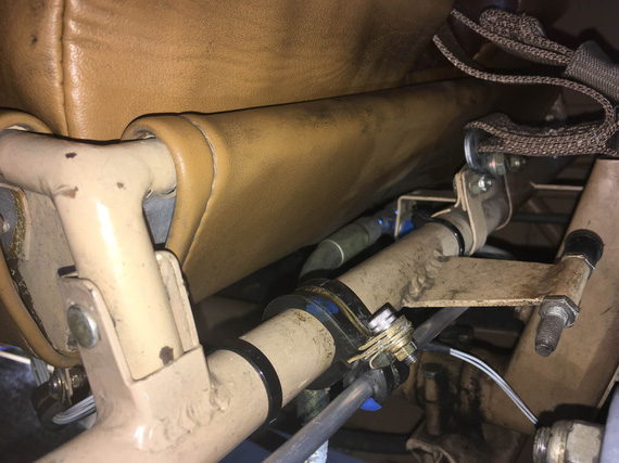
ADEL One
That one took ... an hour! Very nasty spot and hard to get to. I had to find a better way...
Now, there are fancy mods to ViceGrips (or you can buy them for sizeable chunks of cash pre-made) to hold ADEL clamps together while you're inserting the screw and starting the nut. I don't have them.
Some people use safety wire.
I decided to try...
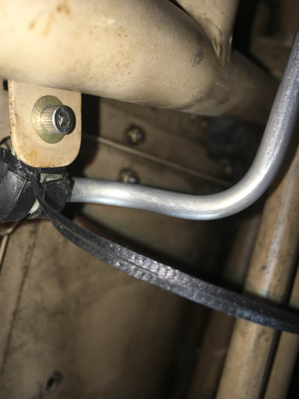
Lacing cord!
It works great, too! Just double up and "noose" it around - it holds a clamp like a charm in the "closed" position while you fiddle with the nut! Even Jack came out to see that.
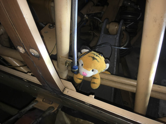
Jack inspecting the work
With those clamps installed, I had to tie a bundle of wires going across the tube to the front stick's PTT switch. That one was one hell of a contortion exercise, under the front seat's front edge and behind the stick, but I managed after a couple of tries.
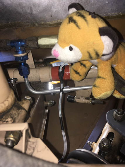
Lacing the wires to brake fluid line and structure
And finally, a couple more clamps along the length of the line on the fuse to hold it in place there. Some TorqSeal, and we're done!
I worked out a method to these, finally, I think. I use a long (~2 inches) AN3 bolt first to "thread" the clamps on, and then close them with a wrap of lacing cord using the "noose" method ("Method 2" here). I then remove the long bolt, install the final bolt, and start the nut. When the nut brings clamps almost to a close, I cut off the nooses, and tighten the nut. Works like a charm!
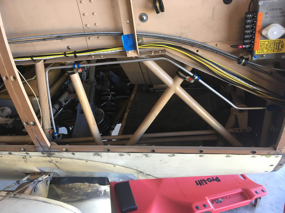
All done!
So, there. A pretty big job now complete - brake system rebuilt, re-bled, and ready to go.
PS: I was considering where to put this - under "2019 Annual" or "Electrical Rebuild" category... decided to pile it into the "Electrical Rebuild", because basically as a part of this rebuild I'm doing a bunch more stuff.. This is basically becoming a "minor restore" project... But still, the main theme is "Electrical Rebuild", and I'm keeping it under this section.
"you're gonna have to key the mike. I can't see you when you nod your head."
-ORD ATC
Up ↑
LR3-C
... mounted, and pretty!
| On: | Oct 09, 2019 |
| In: | [Chickenhouse Charger] Electrical Rebuild |
| Time logged: | 6.6 |
| Tags: | electrical, 6781G, MA5 Charger |
Prior to mounting the newly finished brake line, I wanted to finish fastening everything that's around it - so that I minimize wrenching around the brand new line.
Voltage Regulator is one of the bits that will go right there, so it was to be done.
I was working on it's mounting, on and off, and eventually got stuck with attempting to solder a short grounding strap that was to go under one of the "standoffs" for the regulator.
And then, I was making the new brake line - but now that is done too. I also figured out how to make that ground strap. So. nothing prevented me from completing the voltage regulator install.
But, we're getting ahead of ourselves.
First, the holes.
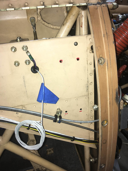
Holes
How do you drill real good, round, quality holes, you ask?
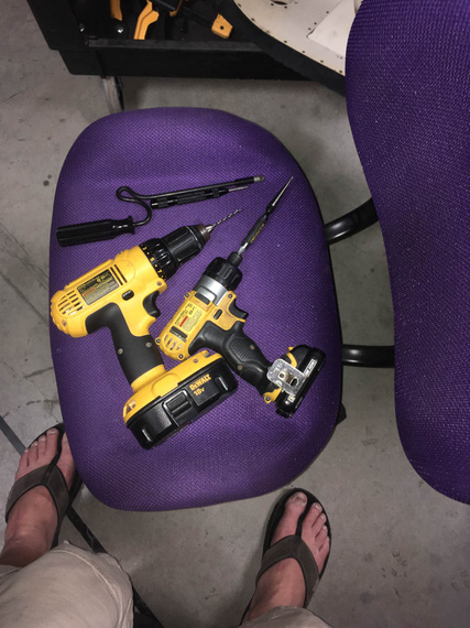
Tools!
Well. All those tools were participating in making of those holes, in sequence. Here's a game: name that sequence!
And then, the mounts. The regulator was to be on standoffs, to "raise" it above that rivet line. The regulator wants two grounds, which will go under two of the standoffs. I also wanted to have a ground strap go under a standoff.
Now, I have to explain the ground strap. I already mentioned spending quality time trying to make it.
I want to set up good grounding architecture in my all new electrical. This side conduit, to which the regulator is mounting, is key.
It's continuous, and aluminum - so it presents a really nice grounding point. I am planning to add jumpers between it and the firewall, and it and the instrument panel, tying it all up nicely. Loads will be grounded to the conduit, firewall, and instrument panel only.
Since the voltage regulator is right next to the firewall, it's very logical to have the ground strap under one of it's stands. And besides, there is already a convenient hole right next to it for the firewall side of the grounding strap - which is why the strap is very short.
At any rate, those three terminals under three out of four standoffs for the regulator are making hardware stacks of varying thicknesses per standoff, so standoffs need to be individually sized to keep the regulator overall "level" above the conduit.
Another fly in the ointment is that "jog" created by one portion of the conduit riveted on top of another - that has to be accounted for, too.
So four individual standoffs.
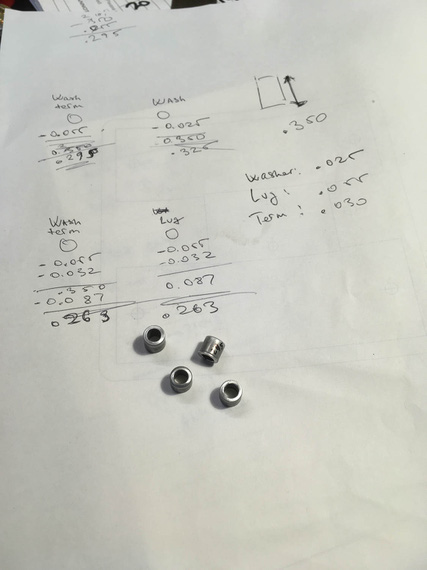
Calc and standoffs
If I had a lathe, I'd do them on the lathe; but my lathe is pickled, waiting for the shop - so, tubing cutter and a bit of luck made them all within 5 thou of the right size.
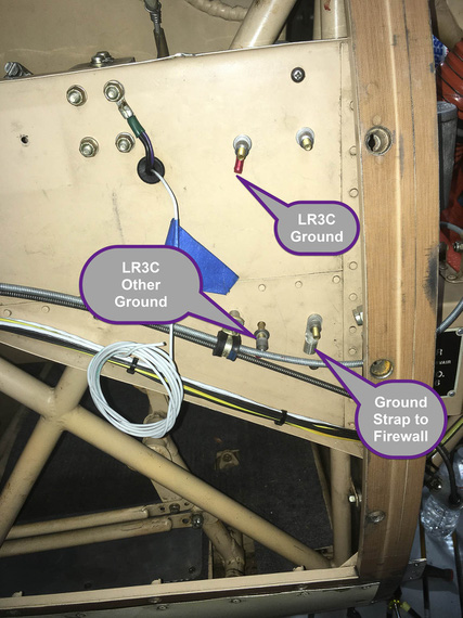
All set up
Here are the stacks, just to give you an idea of the mess I got into :).
Top and bottom left:
- Bolt head
- CAD Plated Washer
- <side conduit>
- SS washer
- Ring Terminal
- Standoff
- SS washer
- <volt reg flange>
- CAD Plated Washer
- Nut
Top right:
- Bolt head
- CAD Plated Washer
- <side conduit>
- SS washer
- Standoff
- SS washer
- <volt reg flange>
- CAD Plated Washer
- Nut
Bottom right:
- Bolt head
- CAD Plated Washer
- <side conduit>
- Ground strap lug
- Standoff
- SS washer
- <volt reg flange>
- CAD Plated Washer
- Nut
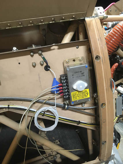
Test mount
Nuts there are temp AN315 nuts.
And now, for the final mounting.
First, scrape all the paint from the side conduit, to ensure good contact (top right doesn't have anything electrical so didn't need to scrape the paint there).
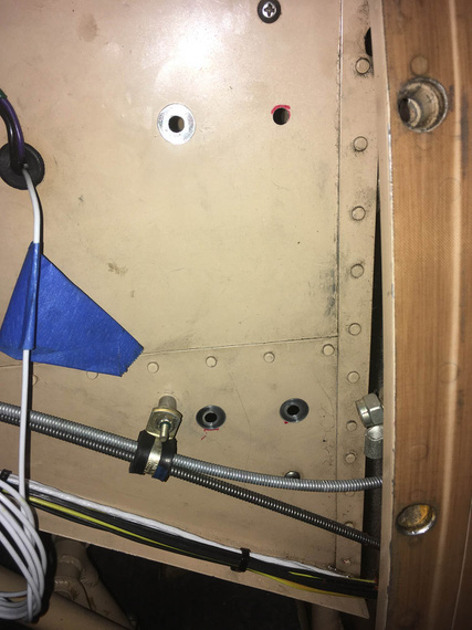
Holes prepped
Then, make the ground strap.
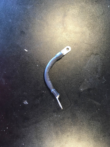
Ground strap
And then.. Well, I wanted to clean up and make sure I mount the bowdens and the engine analyzer harness at least semi-permanently. So, started doing that - discovered that screws in some places, sticking up, were getting in the way of my clamps.
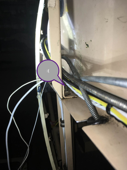
Boo!
No matter.
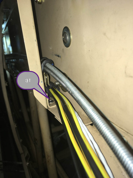
Pretty!
Who said forceps are a doctor's tool?
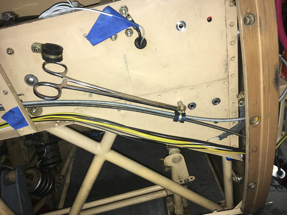
Mounting an adel
At any rate, after making sure that I'm happy with bowdens and probe harness, it was go time!
Intermission
Everywhere I take a nut off, I replace it with MS21042. Half the size, and it supersedes the default AN365 and AN363.
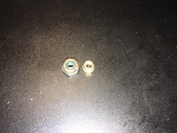
Just nuts!
And by the way, often times it's convenient to use a "grabby thingie" to start them.
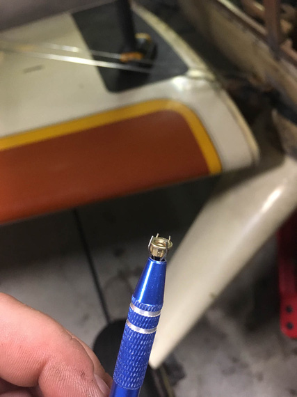
Grabbie
Back to it
Set up the hardware stacks, crimped short lengths of wires into the terminals, hooked up the ground strap...
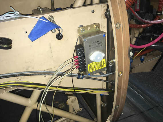
Starting to mount
...and finally, got to use my TorqSeal! I think this is the first fastener I have torqued to it's final state in this project. Milestone!
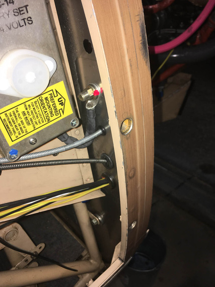
First dab of torqseal
Next, trimmed and crimped the ground wires.
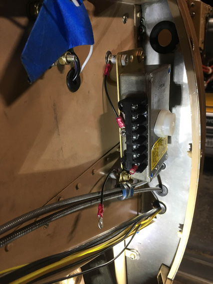
Ground wires
And that was it! Two more dabs of torqseal on the bottom nuts, and installed all the plugs for the holes left over from removing old lines. I'm using AN-6 plugs here.. nice, light, and pretty.
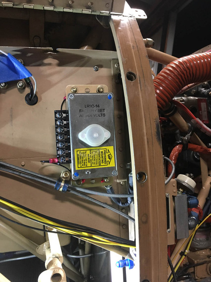
Installed!
Why not top ones as well? Well, I have this pesky gutfeeling that I will hook up an adel to at least one of them to hold the main wiring harness to it. It's just too convenient a spot not to do it.
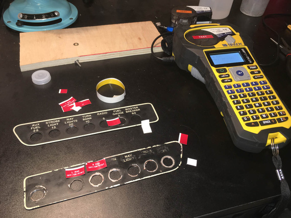
And to top it all off, did a couple of nice placards to remind myself of things :).
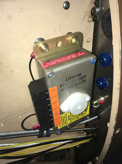
Placards!
An airplane will probably fly a little bit overgross but it sure won't fly without fuel.
Up ↑
Solder, and Good Crimps
... the answer is NOT solder?!
| On: | Oct 08, 2019 |
| In: | [Chickenhouse Charger] Electrical Rebuild |
| Time logged: | 5.5 |
| Tags: | tools, electrical, soldering |
A while back, I wrote a note on my failures at getting good crimps with the hydraulic crimper I had.
My conclusion then was, "solder".
Well, I tried :). I had to make a little bonding strap, maybe 5 inches long.
First time, I cowboyed it - just stuck the strap into the terminal, and soldered away.
In. My. Face.
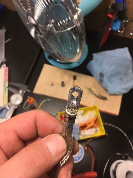
Ugly!
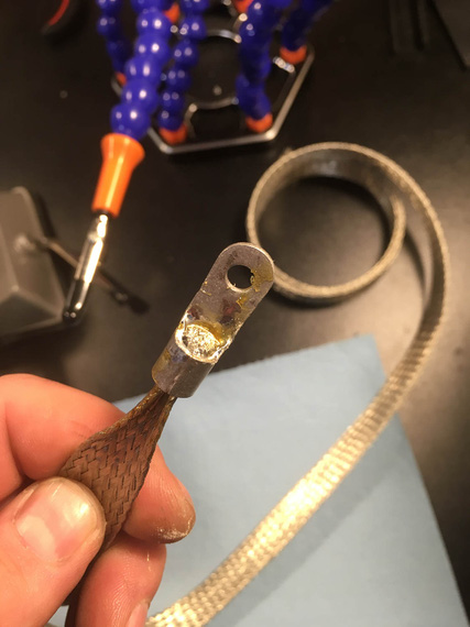
Second try.. I think
I was soldering, de-soldering, soldering again, etc. Trying different positions, and different heating methods (butane torch worked best).
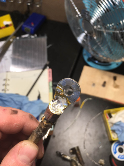
One of the better ones
I eventually started using the "wedge" trick - to wedge a piece of thick wire in between the wire strands, so that the wire gets packed into the barrel of the terminal.
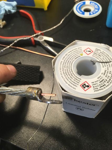
Wedge
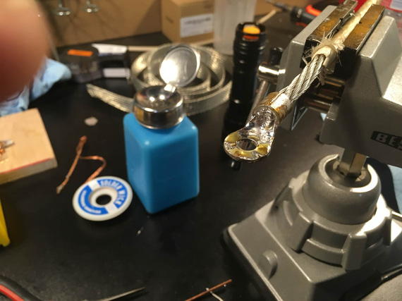
All that yellow crust is rosin flux
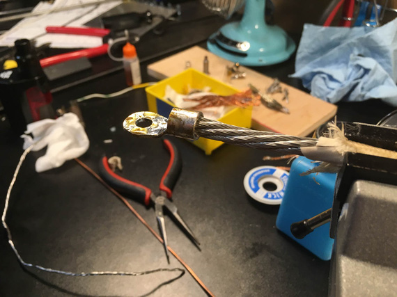
Back side
My main problem was, I was trying to prevent solder wicking as much as I could. And I couldn't. It would make 1 inch or more of the wire perceivably "crusty", and I still won't have the barrel filled in. Remember, I was trying to make a small, short grounding strap, that had to be flexible to bend almost 180 degrees. I was trying to achieve a "crimp quality" break between solid metal and strands, and could not.
When I started thinking about it like that, I realized that what I'm trying to do is likely impossible.
Solder will wick - you can control how much with technique and practice, but you can't prevent it. So my current thinking is, if you solder your large lugs, be ready to support first few inches of wire really well, so that that "crusty" portion of it doesn't move.
So, I tried to Hail Mary the crimps again. Previously, I had them just damn ugly (I linked the article above).
I got a small anvil tool (the kind you insert the barrel of the terminal and whack a pin with a hammer) from Spruce. Thought, 25 bucks was worth a try.
Those crimps were even uglier. I don't know what I expected - I guess that was an act of desperation? I didn't even take a single picture.
But then... I had a minor epiphany.
With the Harbor Freight Crimper, dies are not properly ground for wire sizes. But. But.
Just like with hammering, we can crimp progressively until we "flow" all the strands and the barrel into one solid piece!
Here's the approach (okay, this is the final procedure, first try did not include turning - but I did it (admittedly, accidentally), and liked the results a lot).
- Given wire gauge of, say, 6
- Use die 2 sizes up - so, die marked for #2 wire
- Put the wire in the terminal. Start by squeezing the terminal turned 90 degrees (so "side to side" rather then "top to bottom"). Just give it a gentle oval shape
- Now, turn it 90 degrees and squeeze until the jaws close
- At this point, you will have a somewhat undercrimped joint, as I described in my notes on the crimper; but it's shape will be a perfect hex.
- Now, go 1 size "down" (so, dies marked for #4 wire). Squeeze.
- Stop when you feel it's done shrinking.
Results?
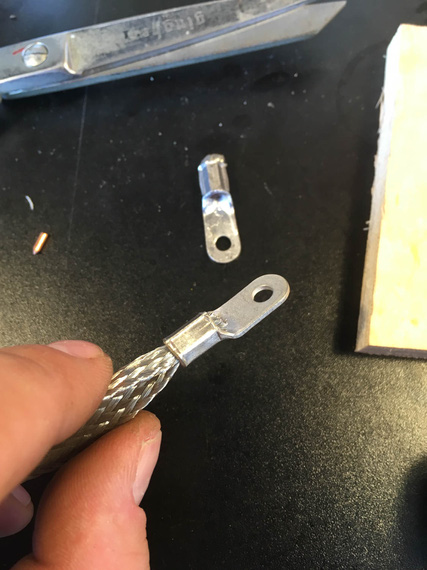
Pretty!
Pretty, ain't she? And, no "wings".
If you don't do the turning trick, it'll still be pretty; but with just a whiff of those "wings" present:
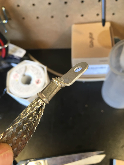
Pretty!
All all this was what... five and a half hours?
Well, I guess, that's the "education" part of the "Education and Recreation" charter of E/AB aviation ;).
Don't drop the aircraft in order to fly the microphone.
Up ↑
Bending Brake Lines
... and fitting in place
| On: | Sep 30, 2019 |
| In: | [Chickenhouse Charger] Electrical Rebuild |
| Time logged: | 12.5 |
| Tags: | 6781G, MA5 Charger, Annual, brakes, bending, tube |
So, yet again, last few weeks turned into working on lots of little bits simultaneously.
But, finally, one of them is done - and therefore, something to log.. ahem, pardon, b-log, about :).
The brake line.
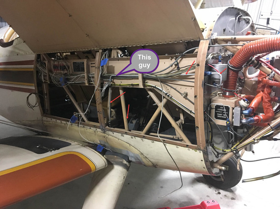
The old brake line
I needed to relocate this bad boy to free up room for the Voltage Regulator. This is the older picture - I have long bent it out of the way and cut off a chunk. It was to be relocated to run below the conduit.
Well, first, we had to locate the hole in the firewall. And that depended on the line to the reservoir, firewall forward.
After having thunk a bit about it, decided to replace the 90 degree fitting in the reservoir with the 45 degree; and the firewall bulkhead fitting with a 90 degree. That'd minimize the amount of bends and make for a neat job.
So, firewall forward we go first - that will locate the bulkhead fitting and the hole.
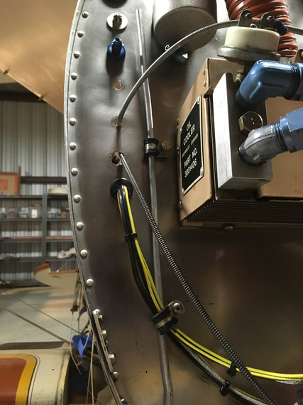
Mockup one
This is with old fittings in the firewall and the reservoir. The clamp on the mockup line is using an existing hole in the firewall - nice happenstance; I'd have to plug it with a "blank" bolt otherwise.
Then, "project" the tube onto the firewall, roughly mark the center, and drill!
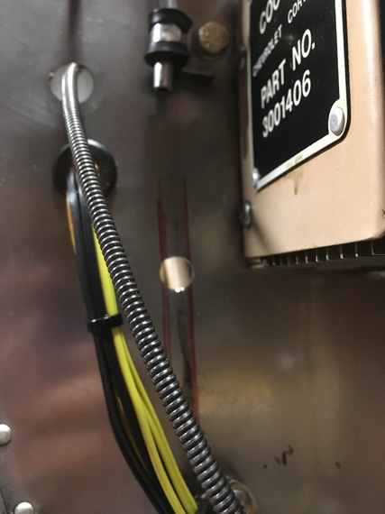
New hole!
And now, to the most fun part. Making the tube.
This was another first - never done tubes and flares before, so first of, had to figure out how to flare them properly.
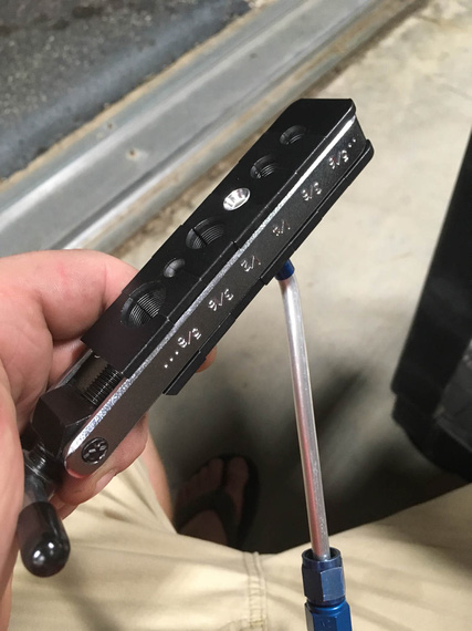
Flaring tool
Question: by how far does the tube have to stick out of it to arrive at the correct size flare?
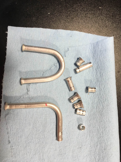
Practice (evidence)
Answer: 0.035. For the -4 tube. :) Yeah, those practice flares are not ALL the ones I made. Just some of them.
OKay, so the next question was how to actually make it fit.
My first thought was,
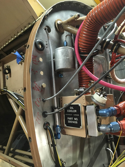
Bottom hooked up, top not bent yet
- Hook up the long portion (bottom)
- Mark out the centerline of where the bend should be
- Bend
The tubing bender has alignments marks for where the marked CL should go for different angles of bends.
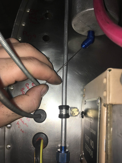
Marking centerline
What I didn't realize is that on this short a run, even a little error (bend being off of the ideal centerline by as little as 1/16") would cause a total misalignment.
It did, of course.
Okay, second try.
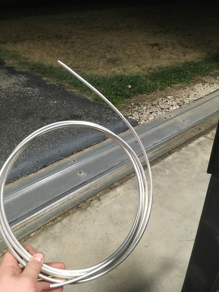
Real material!
I pulled out the roll of the new tubing, too. Partly to motivate me. Partly because I ran out of the chunk I've cut off of the old line.
This time, the idea was to bend it first and get the bend angle just right. Then, trim to correct length.
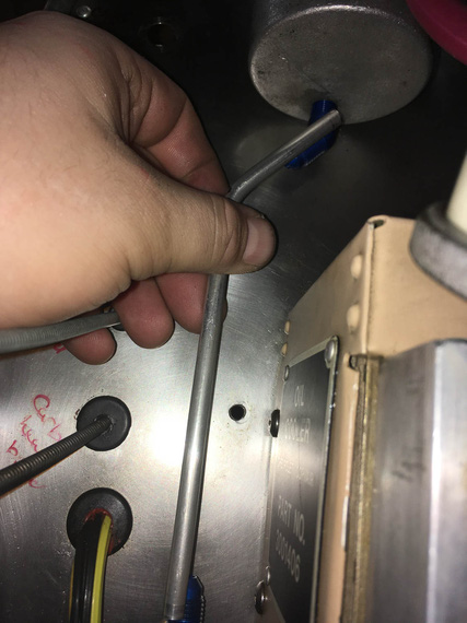
Bend angle first
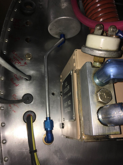
Trim, flare, hook up the bottom and mark the top
This actually worked.
Question. If you have a fitting with a flared end, where to place the cut mark, so that after you cut, and deburr, and flare it, while it's sticking out of the flaring tool (un)-precisely 0.035", it fits?
Answer? I don't know. I think I got lucky :)
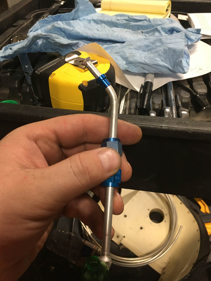
All done
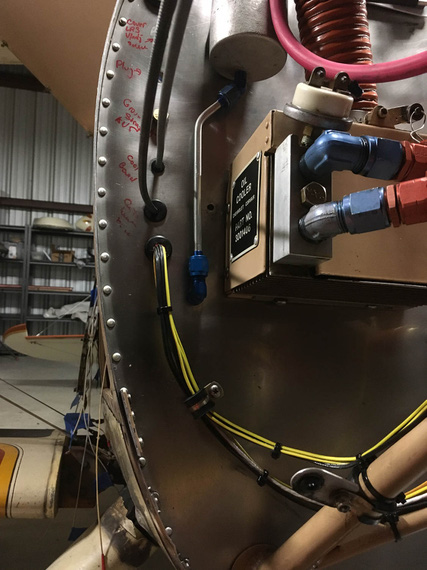
Installed
It fits perfect. I have no idea why the fitting there looks crooked - probably weird camera angle. It's straight :).
Okay. Time for the Big Kahuna - the actual long line, running along the conduit, and under passenger's seat.
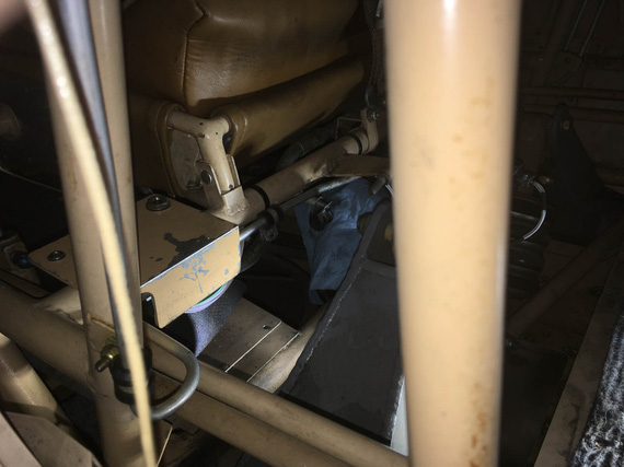
Under the seat it goes..
See that line? It goes down, turns, turns again, and again, and then goes to the center of front seat's front, and goes under.
It was rubbing against structure in a spot, too - so I wanted to clean all that up.
~30 minutes of head scratching yielded clamping arrangement that would work.
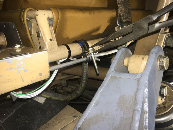
Clamps
By the way, I am stealing this arrangement shamelessly from my friend Mr. Gary Vogt of AuCountry Aviation fame. He uses similar arrangement to organize wires along motor mounts. Genius, really - and I have never seen this before (but I likely am a total idiot, anyway).
One final mock-up, and we're good to go.
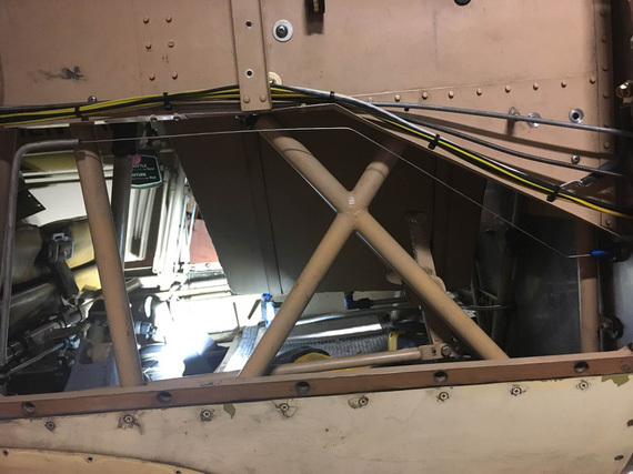
Safety wire for mockup
BTW. How do you make safety wire straight? Chuck it into a drill, and spin a bit :). It'll work harden a touch, and straighten out.
Okay, now, let's do the actual new line.
Unbend a long enough piece of tubing from the roll. Pull out the old line. (and use it as a template!)
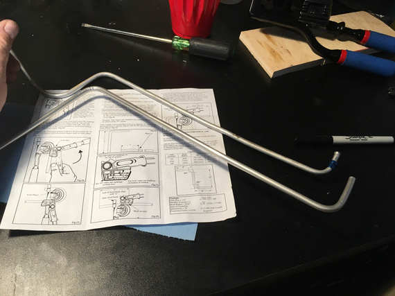
First two bends
Old line on the top, new on the bottom. I made the "tip" (that first section on the left) longer and planned to flare it later - can you guess, will that bite me or not? ;)
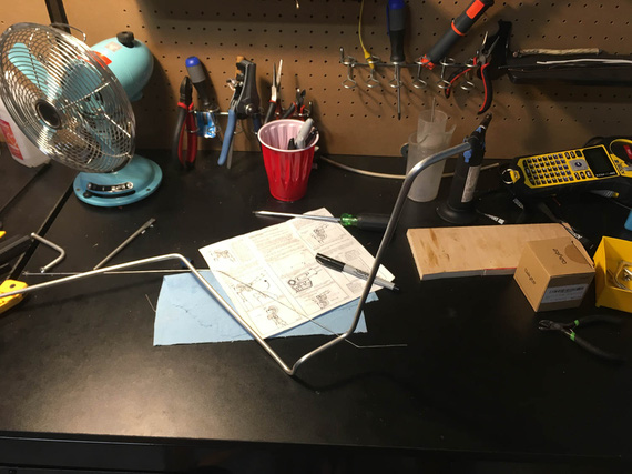
Getting close
Once I got to the point where the complex section (the one that goes from under the seat, to the side of the plane, and then up, and down again to run parallel to the conduit), it was time to try it on.
Maneuver it in.. it fits! Perfect! Bends clear all the right spots and fit in all the tight places.
Okay, now, time to actually attach it to the fitting under the passenger seat, hook it up with temp clamps, and do final bends and trim to final length in place.
But first, I need to flare that end - the one to go under the seat, where I left somewhat a longer stub to be trimmed later.
I trim it. Perfect length.
Crap! It does not go into my flaring tool now. It's way too short for it. WAAAY too short.
See, the flaring tool has some thickness to it. The sleeve has to fit on the tubing before you flare, and takes up another 1/4" of it's length. And, it won't go thru the bend. So there's a certain minimum length of straight tubing required for you to be able to flare it.
And, I already cut it off :( And I can't unbend it - it'll just break.
Okay, I'll admit to this. I did try to unbend it. I annealed it back to soft (torch + sharpie as temp indicator) and actually did succeed at it. But, bend flattens the tube some - and the sleeve still won't go over it.
Besides, bending this big Kahuna was actually not that hard - much easier than I thought, with old line acting as template. And, I had enough tubing. So, I decided to re-bend a new one.
Second try, I flared first. And then, I realized that Remo has probably bent his with a different kind of bender, or had a different kind of flaring tool - my bender would make that first section a bit longer than what the original line had.
Well... it wouldn't interfere with anything (I checked). It'll make it run a bit at an angle, and stick out from the seat a bit more... a bit uglier, but not a big deal (and I'll try to massage it into a bit more parallel run during final install).
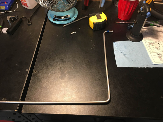
First bends - the first section (with sleeve and flare) is longer than original
Oh well.
Finished bending it, and installed it into the plane.
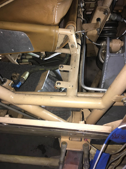
Seat to side...
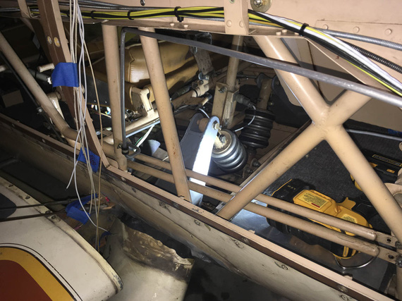
...and up the side
By the way, this is how this looks from under the plane.
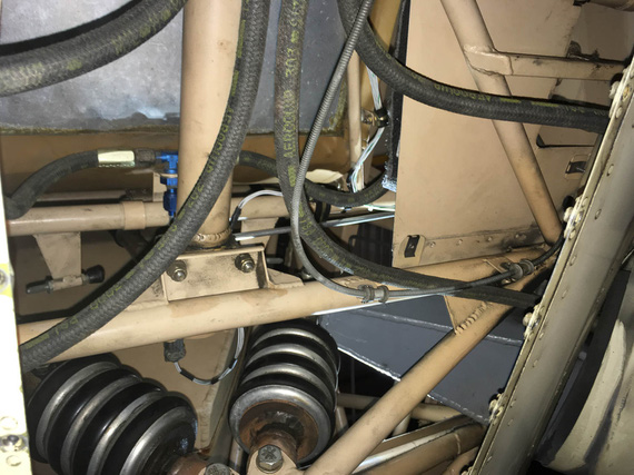
From under
The "front" of the plane is on the bottom of the pic. Can you find the line? (hint - it feeds the T with hoses attached to it. Hoses go to master cylinders under rudder pedals).
OKay, so now to final bends and trimming.
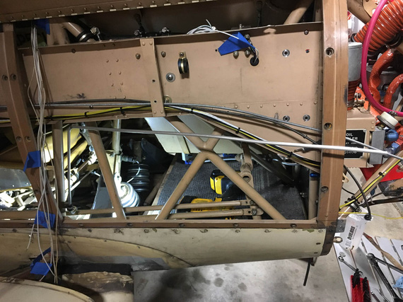
Still needs to be bent and trimmed
There'll need to be two more bends - "down" to follow the conduit and "out" to hook up to the bulkhead fitting on the firewall.
That geometry would need to ensure that I have enough straight tube to successfully flare it - learned my lesson there :).
So, our little safety wire mockup to the rescue.
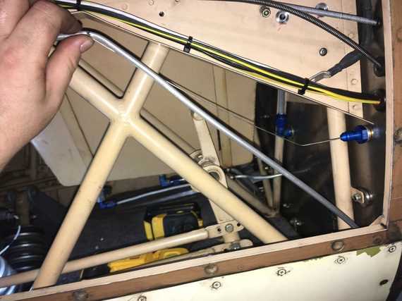
First bend made, marking / eyeballing the second
What I didn't realize is that this long line is much easier than a short stub. Even if you make a mistake, you can massage the line into compliance, "smudging" your mistake over the whole length - mistakes like wrong angle, a bit short here, etc.
Though, marking precisely does help. :)
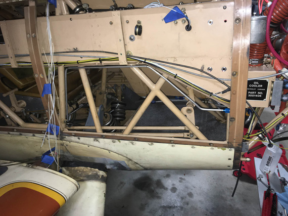
All done
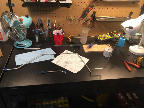
Two new tubes, all ready
I guess, mounting and bleeding is next; but for that, I need to replace the busted cylinder on the wheel, attempt to fix the leak in the parking brake, and re-pack the wheels (or I'll be re-bleeding the brakes later). I want to install the voltage regulator first, too, because that will minimize me messing with fasteners in the vicinity of this line.
Oh well.
PS: at the time of this writing, I am actually more than 50% thru with both of finishing up brakes, and voltage regulator. :).
"Approach, what's the tower?"
"That's a big tall building with glass all around it, but that's not important right now."
-ORD ATC
Up ↑
Drilling the Panel
...misery turned happy times!
| On: | Sep 10, 2019 |
| In: | [Chickenhouse Charger] Electrical Rebuild |
| Time logged: | 5.9 |
| Tags: | 6781G, MA5 Charger, electrical, panel, drilling |
...this is important. Stick a pin in it.
Remo had these nice placards all over the airplane. Professionally done. Very well looking. He probably ordered them somewhere, or used a technique I am not aware of.
These placards are mostly glued on, and do not come off.
How do I know?
Well, I needed to remove one, in the side conduit. Here it is,..
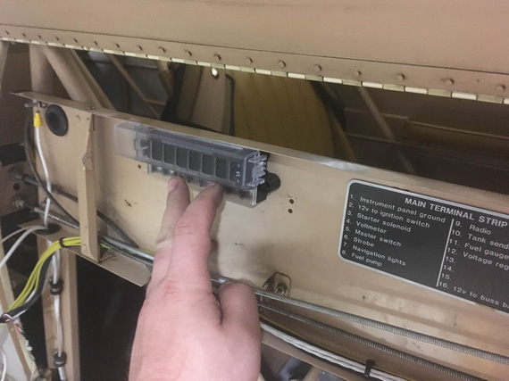
Placard
..to the right of the future fuse block. It gets in the way - there will be another fuse block there to the right of the one on the picture. And I can't rip it off! I can't remove the conduit to immerse it into whatever solvent will cut the glue without some major surgery, so I guess the new fuse block will go on top of it.
Why am I telling you this?
Ha!
You'll see.
Read on.
Switch Anti-Rotation Holes
You have probably figured by now that I have a taste for misery, and for ranting about how miserable that or this was :). If you read a few notes in this Dear Diary, you will notice a trend - that I tend to come up with ways of making myself aggravated, very consistently and reliably.
Well, this time it was the "anti-rotation" holes for switches in the panel; and the plan was to drill them from the back side of the panel not quite all the way thru (yay, no access and contortionism again!)
Every switch, circuit breaker, and certainly, a dimmer, comes with a "keyed" washer to prevent it's rotation. That means you're drilling two holes - one for the appliance (switch, or whatever), and the other for the little tab that's on the washer.
Picture explains this better. Here is a little hole template I quickly drew in Solidworks, properly dimensioned, with washers from (left to right) the circuit breaker, switch, and the dimmer.
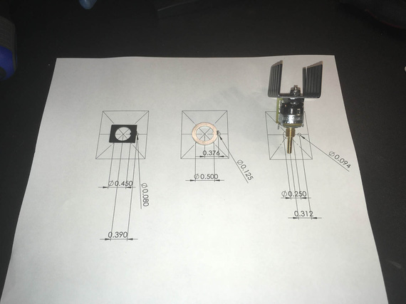
Holes template
See, Remo didn't have those "secondary" holes on the panel - so I had to drill them (especially for the dimmer).
But wait, you ask. If you drill holes, that will be ugly - a hole next to every switch?
Yup. Aha. Agreed! Though the nuts are supposed to cover them, they, I'm pretty sure, from my testing at least, wouldn't have...
No problem! Remo made the panel from 1/8" thick aluminum, and I needed maybe half that much for the tabs to go in. So the plan was to very carefully drill them just deep enough to house the tabs.
Made me a nice little set of templates...
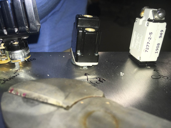
Templates in the making
...out of a small piece of aluminum, drilled holes using my paper template, and cut them up...
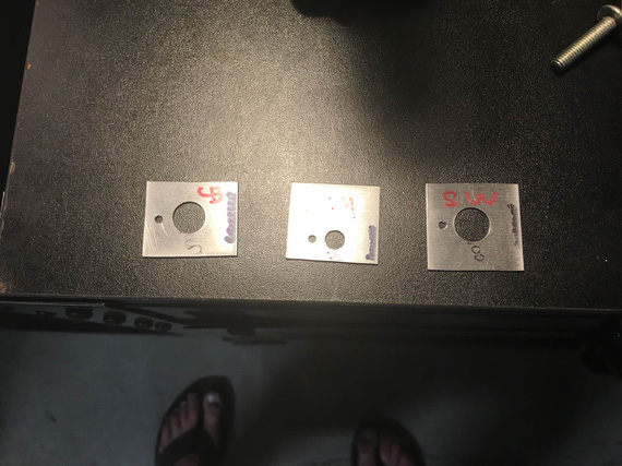
Templates, cut up
...and cleaned up the holes and edges.
The plan was, to put a template like a "washer" around a switch/CB/..., and center punch the secondary, small, hole, thru it. Then, I'll have punch marks to drill, and will have to either get to them from the side of the plane, or, more likely, from the back of the panel while sitting in the seat and not seeing where they are while drilling, using a mirror to position the drill first.
Like I said, I have a taste for misery.
So there we went, punching the back side.
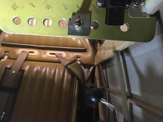
Center-punching on the back side of the panel
Click-clickity-clack.
Cling! Ding! Ding dang dong.. it sounded like a chunk of metal just fell off the plane and dropped on the cockpit floor.
!??!?@??!??! What the h... did I break?!
I crawled out from behind the panel and looked into the cockpit.
On the floor, looking at me, and almost smiling, was...
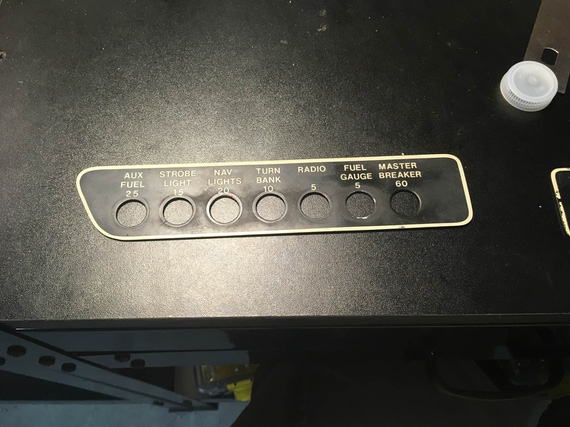
Placard!
...this. Remo's placard that went around the switches. Like so:
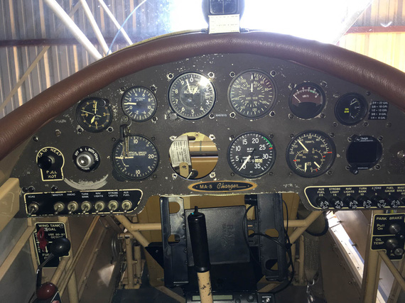
Placards - in place
Wait, wait wait wait. It came off. But it will be held back by the switches' nuts when the switches are in. And.. cover the holes! That means, I don't need to drill the holes from the back side and worry about punching thru (or not going deep enough) - I can comfortably sit in the cockpit and drill them from the front! All the way thru! The placard will cover them! In my search for misery, did I luck out?! :)
In retrospect, this (and the opposite side's) placard were probably not glued. No need - switches' nuts hold them just fine.
They were stuck because Remo probably installed them on top of the paint that didn't fully cure - and it just stuck to the backside of placards over the years, under the pressure from switches' nuts.
I stuck my nail under the opposite side placard, and it came off with a little force.
Ha!
Well, it was smooth sailing from there...
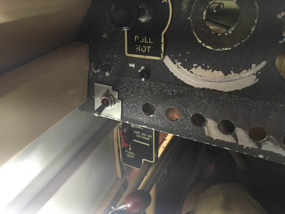
Marking from the front
... relatively speaking, of course. I still had to hold up the vacuum with my knee, and maneuver the sharp drill, making sure to be extra careful not to poke it into anything important (like, fabric on the sides).
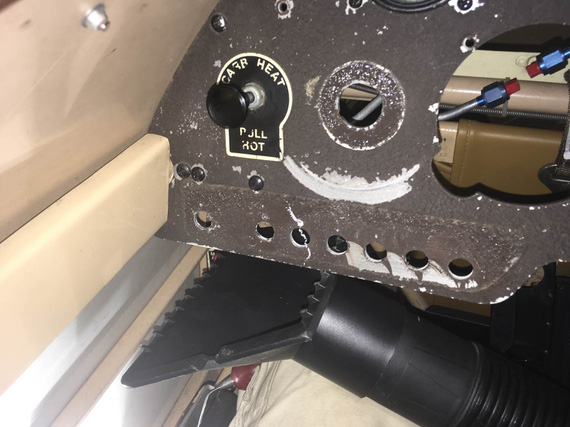
Curlies!
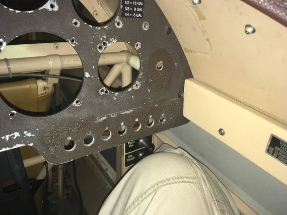
All drilled!
The ones on the corners were annoying; but I already had the drill bit installed into one of my hex drill adapters - so a 90 degree adapter was not an issue. Didn't even need an angle drill.
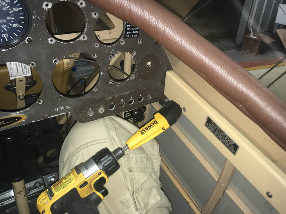
Angle adapter for the side hole
Happy end!
Dimmer Pot
That sucker has 1/4" diameter threads; and all the holes I have in the panel are 1/2... Without some serious bushings, or other mods, or a new hole.. ugh.
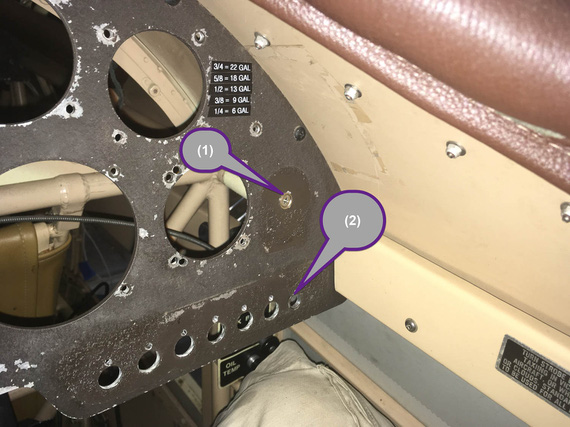
Possible pot locations
I was hoping to stick it into the old "Master Circuit Breaker" hole (marked (2) above), but it was waaaay too big.
Looking around, looking around.... aha! Here's a number 8 or 10 screw plugging a hole! I can enlarge it and we'll be in business! (marked (1)).
Yep. Good luck, buddy. That was an even bigger hole that was plugged with a #8 screw in a countersunk finishing washer... hmmm... maybe that will work out for the pot too?
You know, drilling a #10 countersunk washer to have a 1/4" hole in it is... hard? Annoying? You can't really grip it in any manner without damaging it, you can't hold it in your fingers... I think I lucked out on my third try, with combination of a Unibit and light clamping of that washer in a vice.
With that re-drilled countersunk washer, the pot mounts just fine in hole #2. And #1 got plugged back :).
Compass Mount
Well, after all that excitement compass mount was almost anti climactic. I toyed with the idea of putting it into the panel (and relocating G-meter into a new hole I'd cut around where the ignition switch was - see, after having failed relocating Hobbs there, the idea of still making a bigger hole in the panel keeps nagging me :).
No good. When that much down, too much steel around it confuses the compass to the tune of about 30 degrees... No need to add extra problems in already a magnetically problematic plane.
So, top it was to be. The windshield will get in the way, but I really, really didn't want to take it off (~20 #6 screws and nuts in a tight spot is no fun).
Eyeballed the bracket alignment with the fuselage centerline and put it in the right spot...
Damn! Sharpie's too tall to get in there to mark the holes vertically. "Angle Sharpie Adapter"... hmm..
I know!
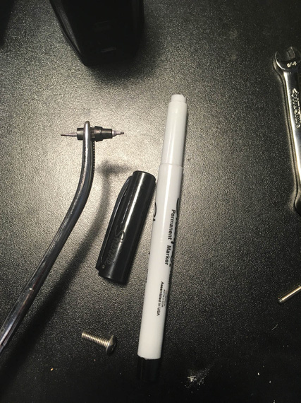
Angle Sharpie Adapter
A bit of disassembly and forceps do the trick ;).
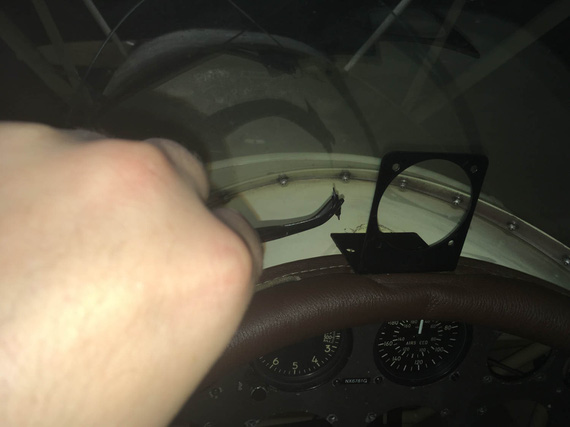
aaaand, mark!
Holes punched and drilled, I added a bit of rubber foam under a portion of the mount to "eat up" uneven surface created by combing...
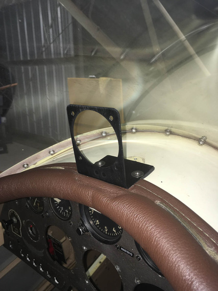
Mount mounted
...and voila...
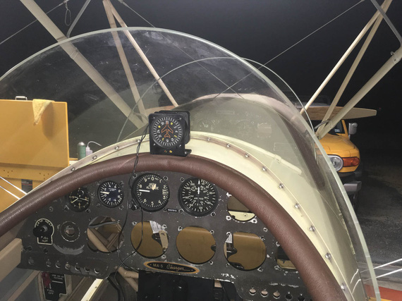
Vertical card compass!
Side note to attentive folks: yes, I know I need brass hardware - those CSK washers and SS CSK screws are temp fasteners I used to test positioning. It will be brass, I promise :).
PPS
Oh, by the way, the best accompaniment (score? ;) ) for working on a biplane is...
... The Chairman, of course!
The three most common phrases in airline aviation are “Was that for us?” “What'd he say?” and “Oh Shit!” Since computers are now involved in flying, a new one has been added: “What's it doing now?"
Up ↑
FWF, Side Conduit, and Panel
...messing around trying things
| On: | Sep 08, 2019 |
| In: | [Chickenhouse Charger] Electrical Rebuild |
| Time logged: | 21.5 |
| Tags: | 6781G, MA5 Charger, electrical, fwf, panel |
I was on the fence about making this entry as multiple separate ones versus just one giant one... After all, it covers quite a few, mostly unrelated, things that I did in the last few days, and it would've made sense to keep them separate.
However; finally decided to make just one big article with all of them. None of them are finished; but somewhat a decent chunk of work is - I think I have mostly figured out where everything will go and how it will all come together.
I guess, what I'm trying to say is, if you clicked on the "Panel Layout" entry in the Log, and are trying to figure out why are you seeing notes on Firewall Forward, just keep scrolling :).
Diagram
I have updated the electrical diagram, version 2 is here.
- Main Connector is gone. I was convinced that reliability concerns outweigh the benefits of having it. Plus, I have very little precious room to work with.
- Physically, it's easier to hook up the LR3C Sense wire to a different spot - on the Shunt stud rather than to the Master Contactor/Starter Contactor jumper directly. It makes no difference, it's the same circuit - just a different hookup spot to it.
- I also fixed some typos, and cleaned up a bit.
Firewall Forward
I started trying things around firewall forward while figuring out routing and lengths for carb control cables, and continued afterwards.
Contactors and Beefy Wires
Contactors
It became obvious fairly quickly that I won't be able to use the nice B&C Starter Contactor because of it's mounting holes not being the same as a very common SS581 Starter Solenoid that was set up by Remo. Also, the way terminals were set up on the B&C Starter Contactor would have made them closer to the carb control cables. And, I didn't want to drill more holes in the firewall.
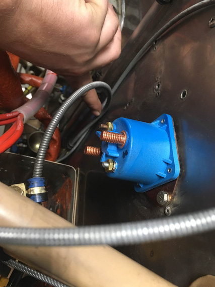
B&C Contactor
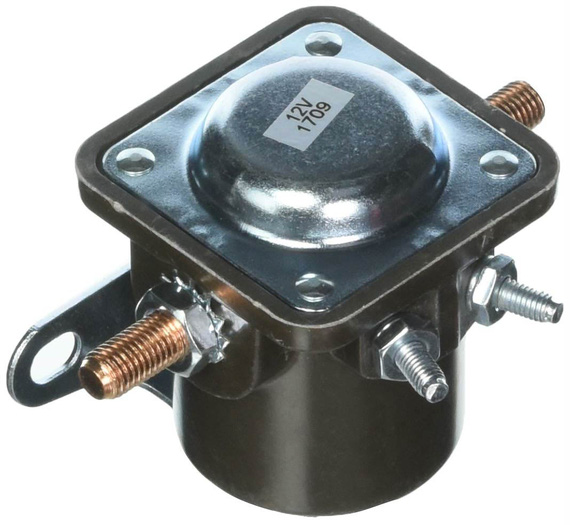
SS581 Contactor
So I decided to go with SS581-style and ordered one from Vans. While waiting for it, I used the old one just to mock things up.
And because it doesn't have the spike catcher diode, I had to get me a couple IN5400s, and soldered an extension lead to one of them.
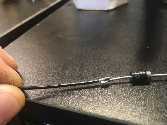
Extension lead
The other leg will get a crimp ring terminal. I had to do that 'cause the diode leads themselves weren't long enough.
Battery and Starter Wires
Those are the thickest wires, and routing them is more complicated than the other ones. In addition, the battery + -> master contactor wire is the only wire that can't be turned off, and therefore needs to be very well thought out and as short as possible.
Here's something else, too. The Charger was set up to ground the battery to the motor. So far, so good - starter is by far the largest consumer in the electrical system. However, nothing was done to ground the motor to the rest of the airplane!
So the rest of the system was probably grounded via whatever metal to metal connections there were on the motor. Control cables and braided fuel and oil hoses? ;) Airbox bowden "carb heat" cable... I can't think of much more else.
Initially, I was planning to run a ground strap braid from the battery negative to one of the bolts holding the battery box to the firewall, but with fuel system components and control cables around, just couldn't figure out a good way to run it and support it. I had to end up settling for running it to the engine mount instead.
So the bottom line is, the negative 4GA cable is gonna go to the motor, and parallel to it a braid will go to the motor mount. I also figured out a clamp arrangement with some standoffs that will keep the wires neat and organized.
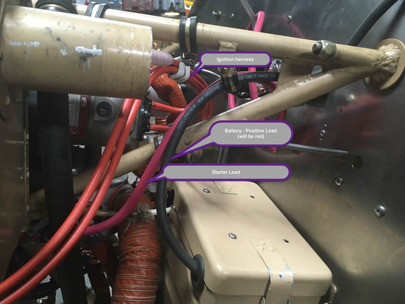
Beefy Wires - side view
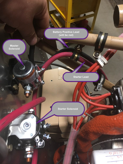
Beefy Wires - top view
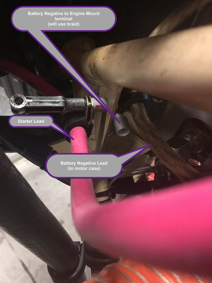
Negative leads and grounding
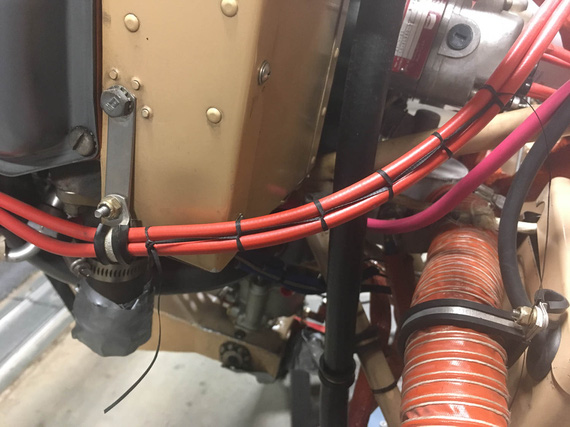
Oh hey, and I practiced my lacing on those ignition wires. One of my plans is to excise all the zipties I can get to, and replace them with lacing cord ;).
Laces
ANLs and Shunt
ANLs and the Ammeter Shunt will go to where no man had go... 'cuse me, to where the old Voltage Regulator was. Like this:
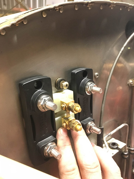
ANLs and Shunt placement
I will need to make a backplate for them to re-use the old voltage regulator mounts, and not have to drill new holes in the firewall. I used my Solidworks templating trick, and made me a nice template...
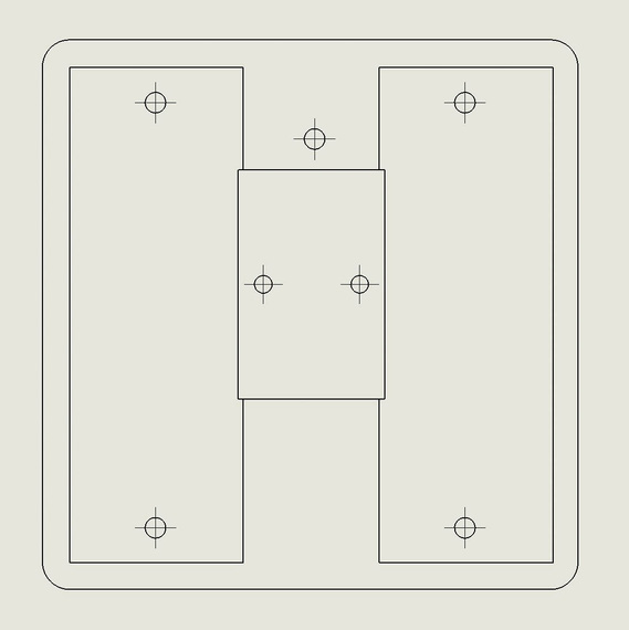
ANL template
... and a mockup (with material, as usual, courtesy of USPS).
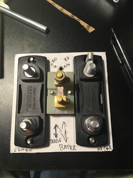
Mockup backplate
The shunt is offset "down" due to the top hole in the backplate (which will have one of three holddown screws to hook up to the old voltage regulator mounts), and I couldn't use buss bar stock to connect the stud terminals on the shunt and ANL bases - if I were to do that, it would not let the ANL covers to come on. So, before doing anything drastic, I decided to check to see how it would look with the wire jumpers
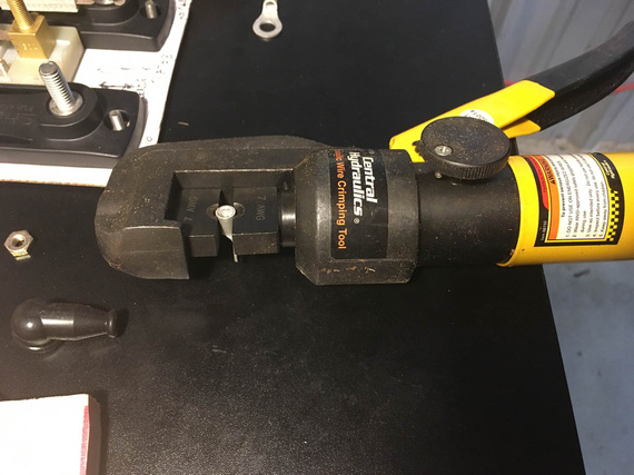
Crimper
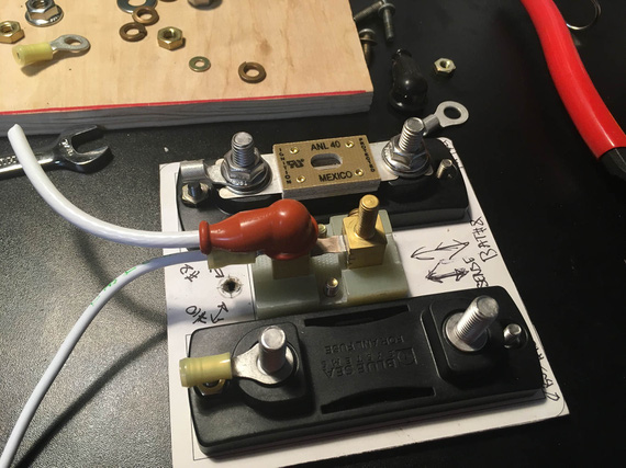
One side done
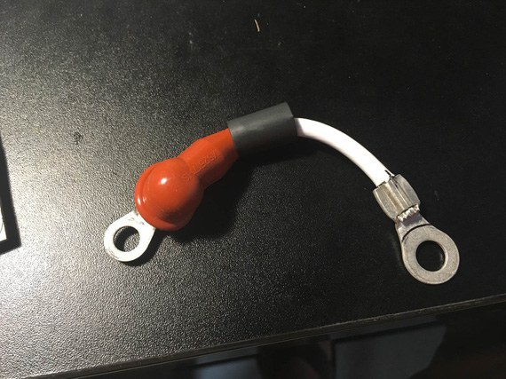
Second ring on the jumper
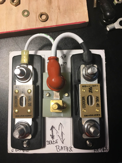
Done
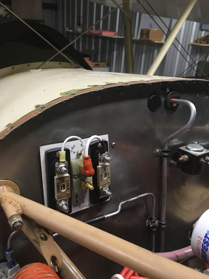
On the firewall
I liked the way jumpers came out a lot, and will probably keep them that way. They do add just a bit of weight, but not enough for me to worry about.
Side Conduit
The Voltage Regulator and the Main Terminal/Fuse Block were to go to the Side Conduit running alongside the fuselage.
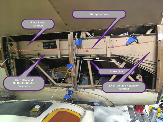
Rough component locations
I had to relocate the bowdens lower to free up some space. The Oil Cooler box on this plane is all sorts of weird, including a flapper valve controlled by one of those bowdens that closes up the airflow to it (which is not enough to begin with; being a 1.5" SCAT takeoff off of back baffle.. but don't get me started on that). That cable turned out to be too short when relocated - but I lucked out - Glenn had a bowden going to the Rotec TBI that I removed for "prime" function, and that bowden was plenty long. I'll trim it to final length when I'm done in that side conduit.
The brake tube was running inside the conduit, and I will have to relocate it to run below the conduit and be supported by adel clamps. For now, I unhooked it and used it to somewhat mock up the new run. Tube and fittings ordered, and tubing bender already here!
Fuse Block
I was gonna use a 20-position fuse block from B&C. Well, that didn't go too well.
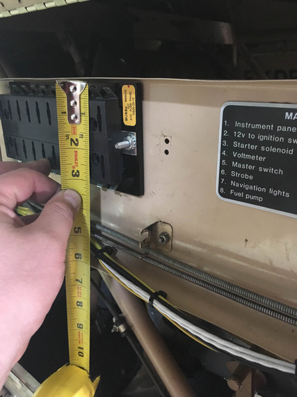
Fuse block
Tight! I basically lose the whole top row of fuses with it. Not enough room....
After poking around the Internets for a bit, came to these nice fuse blocks made by Blue Sea Systems. Longest ones they have are 8 fuses, so I will need two (if I recall correctly, I have 13 fuses in the diagram currently, and I want some spare positions for later if I need them).
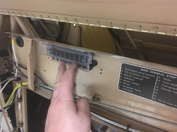
Blue Sea Systems fuse block
Much better! Plus, they use ring terminals rather than tabs - and while tabs are light and simple, I don't like them. Removing them is hard, and, when removed, the terminal loses a lot of it's grip. It's almost like an "assemble once" type deal.
Voltage Regulator
With how the wire harness is gonna go in that conduit, and with bowdens being where they are, the best orientation for the Voltage Regulator would've been "upside down", with terminal strip up.
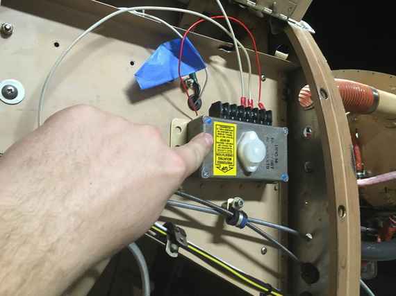
Upside Down orientation
Damn you, the yellow sticker on the regulator! DAMN you! (hint: read it :) ).
Mounting it sideways, I'd have a line of rivet heads under it - which I didn't want to deal with.
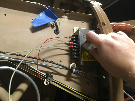
Sideways orientation
And mounting it down... Down was annoying because of the clamp for bowdens and bowdens close there. That would also complicate wiring.
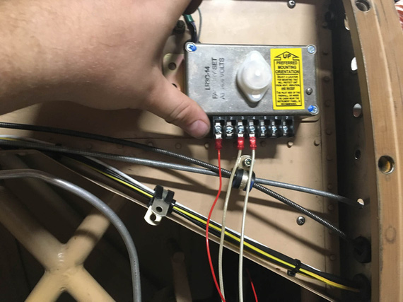
Down orientation
Upside down would've been perfect... except for that yellow sticker :). So, I decided to Hail Mary and asked nice folks at B&C about what they thought.
See, the problem is I know why they wanted the terminal strip to be pointed down. It's so that water won't get into the box in case of condensation accumulating on it. But I thought, maybe I can seal it somehow?
The answer from TJ at B&C was a resounding no. Right side up, sideways - but not upside down.
So I mocked up the right side up mounting...
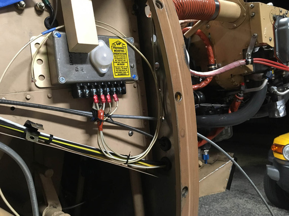
Right side up mockup
Yuck. Yeah; it'd work; but it's ugly as hell.
The only other option would be sideways, but on "standoffs" of sorts to clear the rivet heads. I mentioned that to TJ, and he said that that could work, but I should check if I can access the voltage adjustment screw on the top of the box.
Damn it! I forgot about it. On the top of the box there's a plug over a hole that opens up access to a tiny screw to adjust buss voltage - basically, to fine tune how much volts the battery sees. Not something you do often, but you want to be able to do it.
But then, TJ mentioned that he saw the holes in the firewall and that might be the saving grace.
Bingo!
I tried it out again in vertical, now with mocked up standoffs
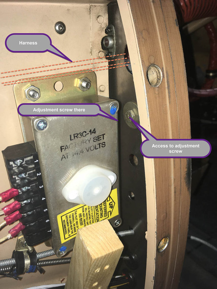
Vertical
With just enough aggravation due to bad access (mandatory in aviation pretty much), you can undo the bolt covering the hole in the firewall (this hole was left over from the brake line relocation), pop the plug on the voltage regulator, and just have enough access to the adjustment screw.
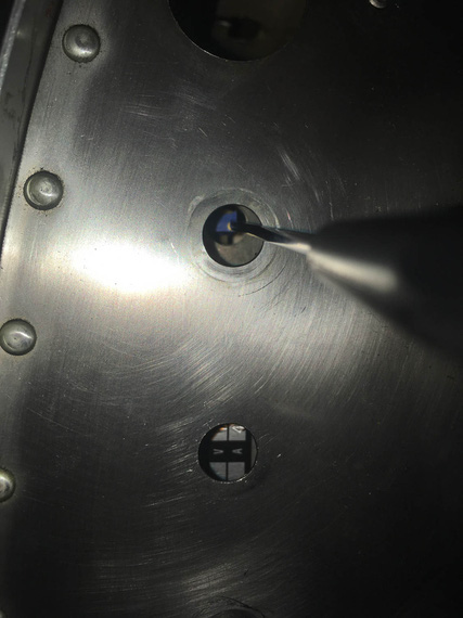
Adjustment screw - firewall side
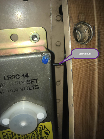
Adjustment screw - conduit side
We got ourselves a winner, I think!
Panels
Hobbs
Hobbs was on the front panel, probably because of space issues on the rear panel.
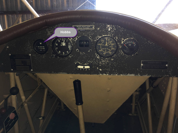
Hobbs meter
"Aux Generator", eh? :) (read what the gauge says).
Well, I had this unsightly hole left over after removing the ignition key switch...
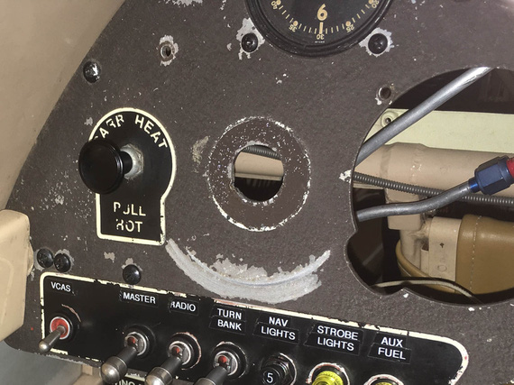
Unsightly hole
... and I thought, maybe I could put the Hobbs back there?
My initial tests with one of the 2 1/4 gauges I have removed seemed to have been okay: there was just enough room in there to get another 2 1/4 gauge in.
So, I got me a very nice panel punch that could make a nice, round, clean hole in place.
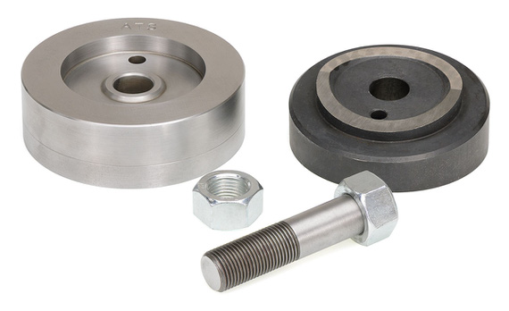
Instrument Hole Punch
Well, next was to remove the Hobbs from the front panel. That was an hour of contortionism. The Hobbs is held by an aluminum backplate and four nylock nuts, so I had to have a wrench over them the whole time. Oh, the screws are way too long BTW, so taking all them out took about five times more turns than it should've, while I was wondering if my wrists will take this much flexing, twisting, and bending any longer.
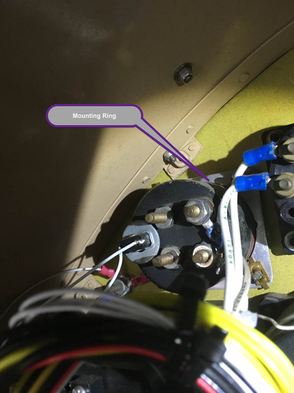
Mounting ring
This is a pic from the fuel quantity gauge held in the same manner, but here he's using brass flat type nuts that you can hold with your fingers. On the Hobbs, it was nylocks.
Anyway, I got it out. And then, started setting up for punching that hole. Removed VSI to give me a bit more room to work with.
I tried to reconstruct exactly what happened next in my memory to write it down here, and could not. I was basically fiddling, checking clearances, making sure I'll be able to hook up the punch and center the hole, have enough room for the mounting ring in the back and clear everything I had to clear, when I discovered that...
The Hobbs was not a standard 2 1/4 inch gauge - it was a touch bigger. So the hole that I would've made would've been too small for it. And that if I punched the hole, I would've been just left with a bigger hole and nothing to put in there.
Damn, damn, damn! Damn you, assumptions that every "small" gauge on an airplane is 2 1/4!
And I had the expensive punch that I had no use for :(.
Oh well. Thanks God I actually did not do it - only to have a larger hole to plug up. I guess, that Hobbs is (thru more contortionism) going back to the front panel.
As they say, Le Sigh.
Switches
Finally, something fun! I put in the switches to play with layout. Here's the first, and (after playing with moving things around and pretend turning them on and off), the best, layout.
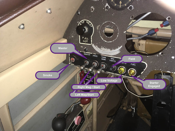
Left side
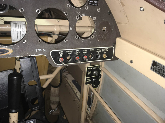
Right side
On the right side, I might clump the switches together, or leave them as on the picture, to "match" the placards (those are left over placards from fuses that were there in the old electrical system). The little brass knob on the right is gonna be panel lighting control pot.
Compass
I am going to replace Pilot's whiskey compass with a vertical card one - yes, I am directionally retarded :) It's not that expensive a mod in the grand scheme of things; and is the only directional instrument available to pilot on this plane (no DG ;) ).
It's a bit taller than the whiskey compass, so I'm playing with different mount locations. I think this is what it will be; with shock isolating rubber pad under the mount where the gap is at the moment.
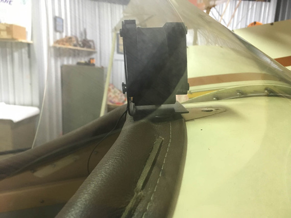
Compass
Fuel Sender Crimps
One of the evenings, I wanted to make sure the Fuel Gauge was still okay (I had a suspicion that it wasn't - turned out to be false).
But first, I wanted to clean up the wiring on the tank sender.
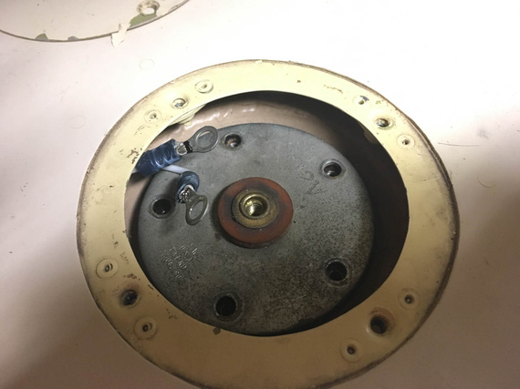
Before
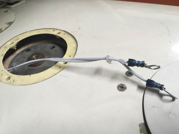
Before
The terminals on it are "automotive" style, without insulation support.
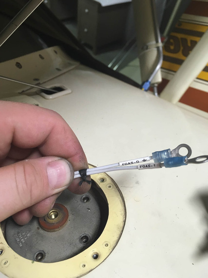
After
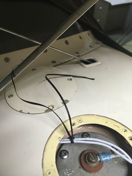
After
There. No zipties, good terminals, and marked :)
Let's make a 360 and get the hell out of here!?!
Up ↑
Harbor Freight Hydraulic Crimper
... the answer is: solder!
| On: | Sep 07, 2019 |
| In: | [Blog] |
| Tags: | tools, electrical |
Doing the electrical rebuild on the Charger, I needed to terminate quite a few of heavy wires with large lug type Amp terminal rings.
I had a Harbor Freight hydraulic crimper lying around that I got to crimp a couple wires when I was installing CRG-30P on the Cheetah, and was planning on using it; though the type of crimps produced by it kinda bugged me.
After doing a few crimps, I decided to burn a few terminals and do a proper test.
The Crimper
Normally, crimpers for large size terminals are super expensive; but Harbor Freight, as usual, sells a hydraulic crimper with large dies for just about fifty bucks.
Here it is, in it's full glory.
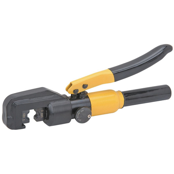
Crimper
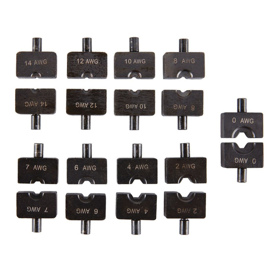
Dies
Technically, the way it's designed is it's supposed to produce these nice hexagonal crimps. Or at least, I think that's what they were trying to do.
But those familiar with crimpers know that the key is in good dies; and that's were most of the money is. Damn, "regular" stripping dies for StripMaster are what, $10; while milspec dies are what, $150? Now; of course there's diminishing returns there - in the case of StripMaster, regular dies work just fine for most applications.
Here's the problem with HF Crimper dies. The holes in them are severely undersized, which makes them produce "flat", rather than hexagonal crimps. We can't know if this is by design. What I tried to do is to research what others are doing, and to run a few "is this a good crimp" tests.
The Test Setup
I was crimping chunks of 8 AWG MIL-W-22759/16 wire into AMP Battery Terminals.
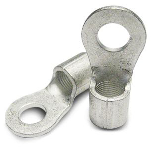
The Terminal
After crimping, the terminals were hacksawed in the middle of the crimp, and polished to see if there were any voids or visible wire strands. A good crimp must be "gas tight". In other words, all the metal has to be pushed together hard enough to become a single piece of metal for all intents and purposes.
Using 8 AWG dies
For baseline, I used the HF die marked for 8 AWG.
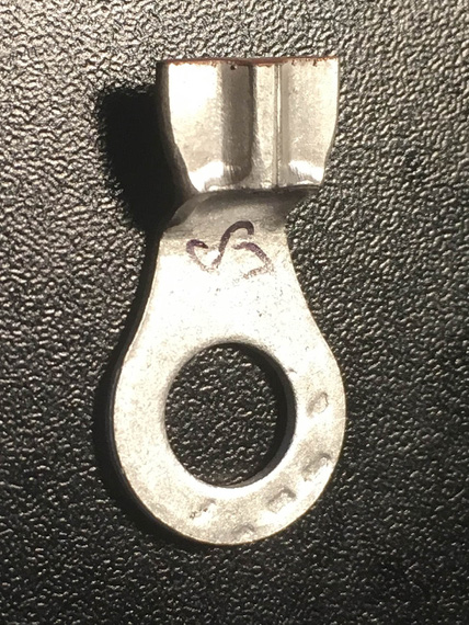
8 AWG die / crimp

8 AWG die / crimp
As you can see, using the "nominal" die produces this weird, flattish-with-a-bulge crimp. What's worse is it adds this strange "jog" to the terminal lengthwise, and scrapes the metal inward where the crimp starts. That's lots of stress risers.

8 AWG die / cutaway
The crimp quality is good though. There are a few specks of shavings I didn't clean off - those are not defects.
Using 6 AWG Dies
I went next size up, to dies marked for 6 AWG. That produced the same crimp as for 8 AWG, but with "wings" being thinner - almost paper-thin. I also didn't like how it mangled the terminal even more.
Somebody online mentioned that they rotated the crimp 90 degrees and did it again to "push the wings in" and I tried that.
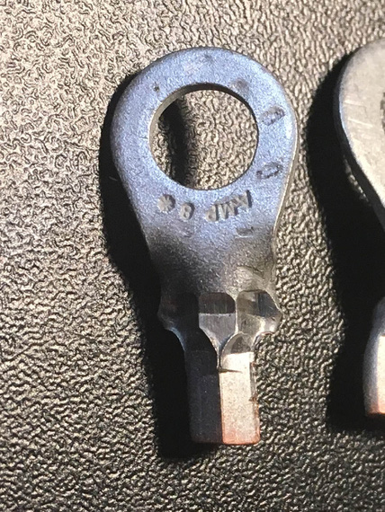
6 AWG die / crimp

6 AWG die / crimp
I think the resulting crimp, while tight, is too rough to be acceptable. It almost feels tortured.

6 AWG die / cutaway
Inside though, it's all nice and compressed.
Using 4 AWG Dies
Finally, I tried 4 AWG dies.

4 AWG die / crimp
This crimp almost looks good. The jog is almost not there, and it has nice hexagonal shape. "Wings" are almost not present.
However, the dies closed fully and it felt to me that the metal was not compressed enough (I recall the resistance I felt in the crimper doing the previous two tests, and the resistance I felt on this one was much less).
The cutaway confirmed that.

4 AWG die / cutaway
Those imperfections on the cutaway are voids left from not enough compression force applied.
Conclusion
Well, it's a sad one really. If you want to use the HF tool, then you probably should use dies that make those "winged" style crimps (like the one produced in my first test), and suck up the jog and other imperfections.
I have posted my findings on AeroElectric list, and the conclusions seems to be supported - the dies are horrible, and to make them real good one would need to rework them significantly.
Or, alternatively, just solder them (here's a nice howto by Mr. Nuckolls) , which is what I am seriously considering.
Update - October 2019
After trying and failing the soldering approach, I have devised a technique of using this crimper to achieve good results. Musings linked in the previous sentence, and here's the jist:
- Given wire gauge of, say, 6
- Use die 2 sizes up - so, die marked for #2 wire
- Put the wire in the terminal. Start by squeezing the terminal turned 90 degrees (so "side to side" rather then "top to bottom"). Just give it a gentle oval shape
- Now, turn it 90 degrees and squeeze until the jaws close
- At this point, you will have a somewhat undercrimped joint, as I described in my notes on the crimper; but it's shape will be a perfect hex.
- Now, go 1 size "down" (so, dies marked for #4 wire). Squeeze.
- Stop when you feel it's done shrinking.

Pretty!
"Don't anybody maintain anything.
-ORD ATC
Up ↑
Carb Control Cables
...just measuring
| On: | Sep 01, 2019 |
| In: | [Chickenhouse Charger] Electrical Rebuild |
| Time logged: | 9.3 |
| Tags: | 6781G, MA5 Charger, carb, throttle, mixture, cables, controls, engine, fwf |
Even before Oshkosh, I have decided to replace the Rotec TBI the Charger had when I got it with a good old MA4-SPA carb. In short, I do not trust the damn thing - especially with it being the sole component providing two out of three vertices of the proverbial fire triangle to the motor. That reminds me, I need to summarize my thoughts on Rotec...
Regardless, one of the things I got at Oshkosh was a rebuilt MA4-SPA from Spruce, and it was sitting in the hangar waiting it's turn. I knew I would need to order new control cables for it, so I decided to get that going, after all the alternator business was finished, because getting those cables will take me a bit.
Here's a fun aside. I knew this motor had a MA4 carb and Glenn "upgraded" it to the Rotec TBI. What I didn't know was precisely what kind of MA4-SPA it had (and there are quite a few models of that carb).
No problem. At Oshkosh, I went to nice folks from Tempest (which now owns MA Carbs) and had a very nice conversation with them. I asked if I should buy the carb from them, and they recommended Spruce instead, because it would be cheaper that way. And, they mentioned the $600 core charge (I'll spell this out - you must provide a good "core" (old carburetor) or get charged extra six hundred bucks). Ouch.
Ha! thought I. I am at Oshkosh! What could be easier than getting an old carburetor, especially since it's one of the most widespread models? No problem at all!
Laughing, I ran that by guys from Tempest. They laughed with me, and actually were very very very helpful, telling me what to look for when picking up an old carb.
No cracks in the body. Control arms should be present. Threads nice and not torn up. Venturi present. Etc etc etc.
Well, to the FlyMart we went, and sure enough, on a bench there laid a number of MA4-SPAs present, ranging from $250 to $450. Of course, I picked up the $250 one (it was yellowtagged by the way! In 1995, if I recall), dragged it over to Spruce, ordered a new carb, and handed them the old one I just picked up. So, $350 saved in about half a mile of walking. Not bad!
Here it is, in all it's glory, hooked up to my motor. You guys should admire my "economizer design" gasket. Hmm... I need to patent that and start selling them for $100/pop. Your fuel costs will go to 0! Now, you might not be going too far... but.. Fuel costs! Zero! With all the benefits, not going anywhere is such an insig.... Ahem.

Economizer Gasket

Carb
Well, okay. The carb was on, and cables came next.
The Rotec had it's control cables for mixture and throttle done completely differently than the carb. Glenn reused Throttle cable for Mixture on the TBI - it worked out well. He added a new cable, routed completely differently, for the TBI's Throttle.
Since this motor was originally carbureted, all I had to do is reverse engineer a bit the way Remo did the hookups.
Hehe.
Well, Throttle on the carb side wasn't that bad.
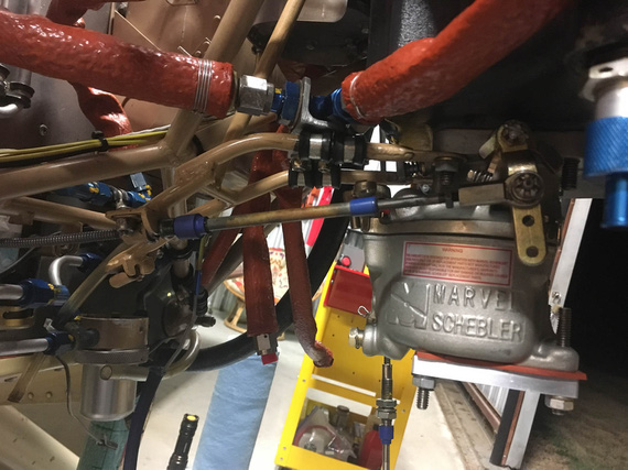
With a Rod End Bearing
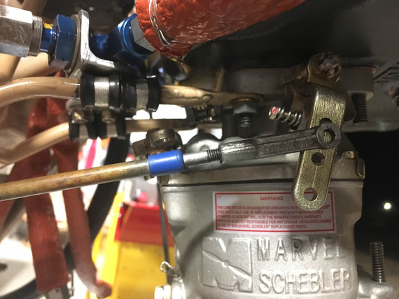
With a Clevis
It actually worked out a bit better with a Clevis, having the cable end centered nicely on the throttle arm. So I decided to do the clevis.
Next was confirming the "throw" - making sure that the throttle control range of motion, whatever it is, is sufficient (in fact, it must have some extra "padding" in it) to move the throttle stop to stop. Boy, was I in for a treat.
This Charger has reversing throttle quadrants, meaning that when the throttle goes forward, the actual control is pulled backward. Since forward on the control must translate into forward on the carburetor, the Charger has bellcranks to reverse the motion once again. These bellcranks are also a nice spot to tune out the range of motion.

Control linkage
See, the relative distance of the top and bottom holes on the bellcrank to it's pivot point "convert" whatever range of motion is on the control (throttle quadrant) side to an appropriate range of motion on the carburetor side.
And Glenn changed them.
Not a surprise. The Rotec TBI had it's controls set up very differently as compared to a carb. Notice how in the picture the color of those bellcranks is somewhat off from the rest of the fuselage? That was my first clue...
My second clue was finding one of those bellcrank plates (minus the bearing) in the box of parts that I got with the airplane.
My third clue was me not being able to get the full range on the throttle.
Crap!
I am absolutely not set up to redo the bellcranks. Though they look simple, unless I want to make them from 3/16" steel, which would make them very, very, VERY heavy, I'd need a TIG welder. Or to MacGyver things with washers. And do quite a lot of trial and error.
I wanted to see if I could luck out.
Credit goes to Glenn here - he made his new bellcranks perfect for the TBI. The range of motion on them was just right... for the TBI. Because of that, they were asymmetrical - so I thought; maybe, just maybe, if I was to try them in different combinations, I would luck out...
And I did!
Now, these two paragraphs of text and one picture is me describing... about 3 or 4 hours of work - tweaking cables, turning bellcranks, checking, rinsing, and repeating. I think I did find a combination of orientation of these that gave me acceptable (but by no means perfect) ranges of motion. I think I lost about an inch on both of the controls, but that's not so bad, after all - you want extra room in your control's range of movement to make absolutely positive you can move the controlled thing stop to stop.
Okay, Mixture's next.
I hooked up the cable that Glenn used for throttle to the mixture control on the carb, to use as a "mock up", and kinda fished it thru.
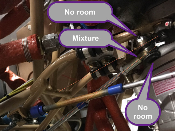
Mixture cable hookup
I had to use a rod end here. The cable wouldn't line up with the control arm on the carb for me to be able to use a Clevis there.... See how angled and offset that hookup is? I think Remo had a solid bowden cable style control there...
Another problem with the Mixture control is that the carb's arm has a 1/4" hole.. the rod ends need a #10 screw; which means that the hole on the carb arm is too large. No biggie though, I'll add a bushing to reduce it.
Yet another problem is that the bolt's head is way too close to the carb bowl, and I had to have it reversed like that (bolt "upside down").
There's not a lot of room on the top either. Planning to fix this problem with using of 1/2 size shear nut, and figuring out the exact bolt length (I ordered every bolt between -4 and -10 sizes).
And now, the routing of those cables.
The throttle cable routing was a given. I did not like too tight a radius in one of it's "turns".
I wanted to try to optimize the routing..... ha. Good luck there buddy! The battery box gets in the way (the battery is in a completely wrong place on this plane... it's reversed with the oil cooler. Oil cooler should be on the left. Battery on the right. This makes controls routing a breeze. But no.....).
I wanted to make sure to keep the mixture cable to not be too close to the beefy 4 AWG cable that will go from the battery to the master relay.
I had to reverse engineer previous routing of the cable, and figure out the best points to hook it up to the firewall.
I wanted to have my ANL fuse bases close to the master and starter relay. Ha! No way, with the control cables the way they would have to be.
All this was an exercise in misery, and lots and lots of time. I wanted too much.
In the end, the routing of the throttle will stay the same; the cable will just be shortened to make one of the turn radiusii bigger. The mixture will go nearby, and curl around the battery box.
I will not be able to use any other arrangement of solenoids and will have to stick to the old one. What's worse, I will not be able to use the new solenoid I got from B&C - it's mounting holes are very different, and, frankly, it's not worth it to drill more holes in already a sieve-like firewall - I'll stick with the classic "style".
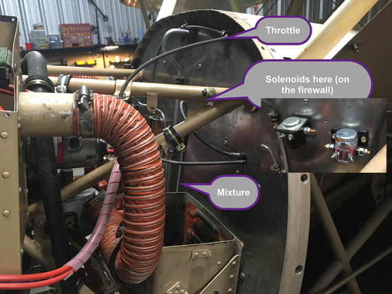
Approx. new routing
The mixture cable does look like it'll interfere with the solenoids, I know. In the final setup, it will be pulled away from the firewall and clamped to a couple of points I found.
...
More bad news? I long noticed a leak from the left brake bleeder valve; and decided to add a new valve to my next order from Spruce. I thought it was a basic valve problem. Well, went to look for it's dimensions, and found out the source of the damn leak, actually... Looks like someone tried to fix a leak there by making a bigger leak. The fun thing was, I didn't notice this before - the brake was too dirty...
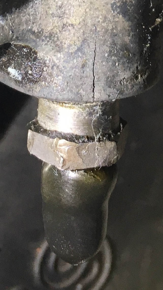
Boo!
Damn.. those cylinder housings are $300 each :(
But hey! I got good news too! I was checking to see if the ANL bases and the shunt will fit where the old voltage regulator was, and they fit perfectly, in just a perfect arrangement!
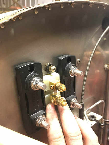
ANL bases and the ammeter shunt
I will reuse old voltage regulator rubber shock isolation mounts (I can't take them out; and they're sufficiently strong), and make a backplate to mount all this goodness to. Frankly, when I found this fit out, I liked it so much I bust out laughing.
And hey! My engine gauges showed up ;) Ain't they pretty?
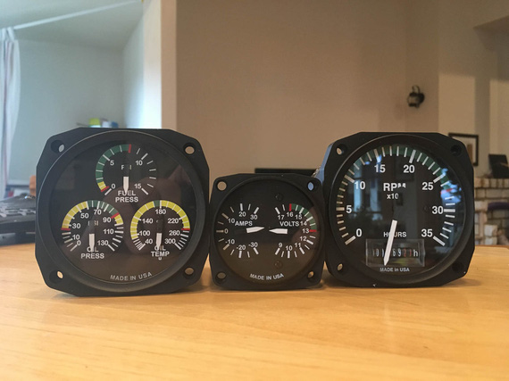
Engine gauges
I’m not speeding officer — I’m just flying low.
Up ↑
Alternator Pivot Arm Bracket
lots of grinding
| On: | Aug 31, 2019 |
| In: | [Chickenhouse Charger] Electrical Rebuild |
| Time logged: | 14.5 |
| Tags: | 6781G, MA5 Charger, alternator, 4130, fabrication, drilling, CAD, SWX |
With baffle support bracket done, the next step on the path to alternator happiness was the pivot arm.
The Problem
... was that the default B&C's pivot arm did interfere with the front baffle hookup brackets.
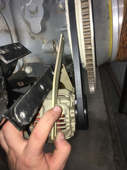
Interference!
That did actually make me pay attention to the very unusual old pivot arm.
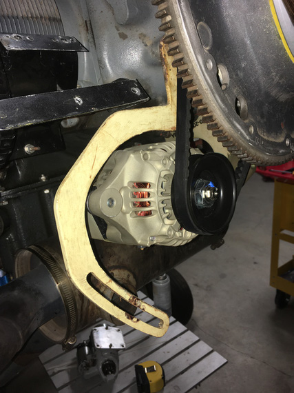
Old one
Nice dogleg, isn't it?
Well, this bracket did not involve any bending, just needed to make the correct one to fit around all the other stuff there on the nose.
Hmm... so how do we do that? Well, first, we need...
The Template
This is not the real template, because (.. read on ;) ). It's the template for the Template.

Start with a piece of heavy paper
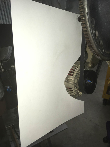
Cut around the alternator
All we need to do with this template is show the location of the hookup hole (top hole, the one that attaches the bracket to the motor); the location of the slot for the alternator to hook up to, and the general outline of the alternator

Alternator bolt location is being marked

Bolt imprints along the "pivot arc"
..and finally, some more "no go" zones to prevent interference with other brackets there:
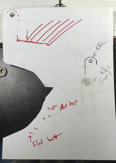
Done!
Notice I also added some "imprints" of the B&C-supplied pivot arm in there, just in case I'd need them.
Okay. I'm lying to you. This template is not the one I used. It was done with the long belt that ended up not working out, so I had to redo the template (thanks God, just the template). The new one was done in the same manner as the one I described above.
Here it is:

The *actual* template used
Okay. So now, we know critical locations of things and where not to go - so, cue in...
Solidworks!
It's magic, I keep telling people.
So, we take our template, and scan it on a scanner, along with a little metal ruler to give us physical dimensions. Then, we go to Solidworks, start a sketch, and insert the scan as "sketch picture". Using the image of the ruler that was scanned in, we tell Solidworks what "one inch" on this picture is. Boom! The image is now dimensionally accurate.
Then, we start drawing around it.
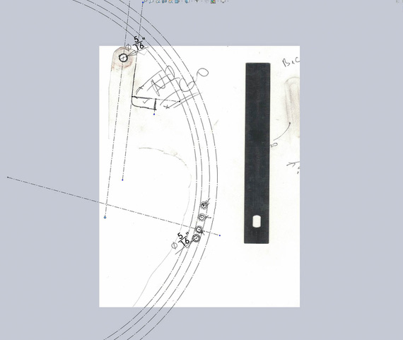
Initial sketch
Above, I positioned the top hole, and the four 5/16" holes around bolt imprints. I then sketched a large circle and made it tangent to three out of four of those holes - it defines the "pivot arc". Then, offsetting it 5/16th gives me the other "side" of the slot; and offsetting it more gives me the "sides" of the bracket in the "pivot arc" area.
I also started sketching the "no go" lines around the top portion of the bracket.

More circles
More circles and lines are added, and off-set. They are not positioned or dimensioned - just made tangent to "no go" lines. You can almost see the outline of the pivot arm, yes? ;)
Now, we take this master sketch; and add arc elements with real lines that we care about.

The arm!
Tada! We got the Solidworks Part.
By the way. How do you "measure" the round over of the B&C arm? Radius gauge? Calipers? Hmmm.. Or...
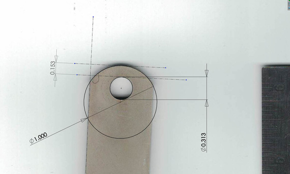
Measuring with Solidworks
Nice, isn't it?
Next, we print the drawing of our new part; making sure our holes' centers are marked (we'll use that later to drill them)

Done!
And, we got ourselves the actual template!
Now, the final test (Many thanks to USPS for providing material for this test)
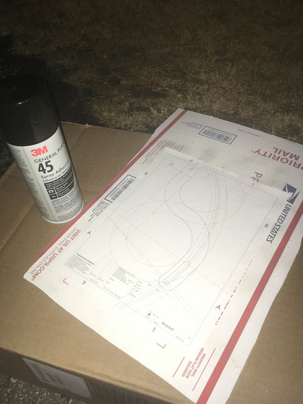
Spray glue and cardboard

I wish I could cut 1/8" steel with X-Acto...
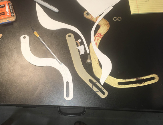
The mockup

Tadaa!!
Okay, we have the real template now, and we know it'll work. And now, comes...
The Grind

1/8" steel is no joke
Nice little sheet of 1/8" 4130 showed up from Spruce some time earlier... I used spray glue to put the print out of the bracket on top of it.
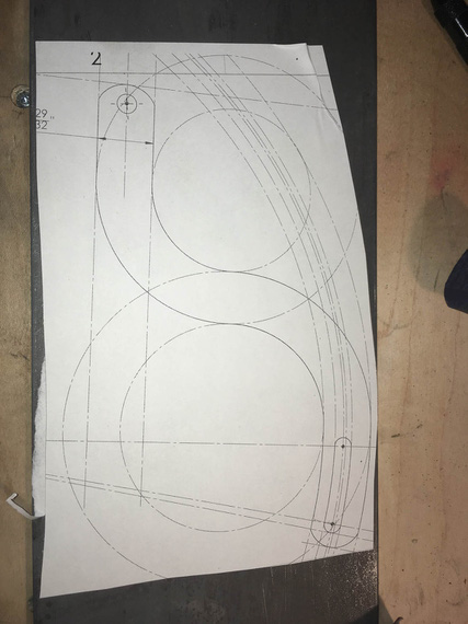
Template on steel
First, all the holes had to be drilled. The drill press I have at the moment is severely underpowered, so I had to step-drill them in four steps.

Curlies!
I got to admit, I am starting to become very fond of pretty steel curlies made by nice drill bits.
Also, lesson number one learned: drilling oil (I used TapMagic) gets under the template, and messes up the glue (and unglues it). I need to figure out a better glue.
I drilled the slot's "start" and "end" holes slightly undersized, and reamed the main attachment hole to 5/16ths exactly.
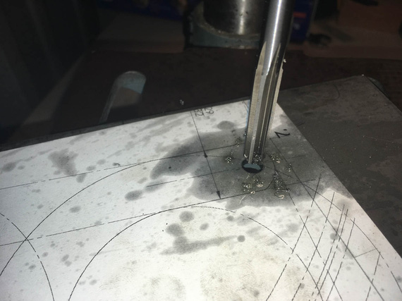
Reamer!
Next, the slot... I rough-drilled small holes around it's perimeter, thinking that a 1/8" shank carbide burr in an air die grinder (basically, Dremel) would work... Ha! It did... for a second ;)
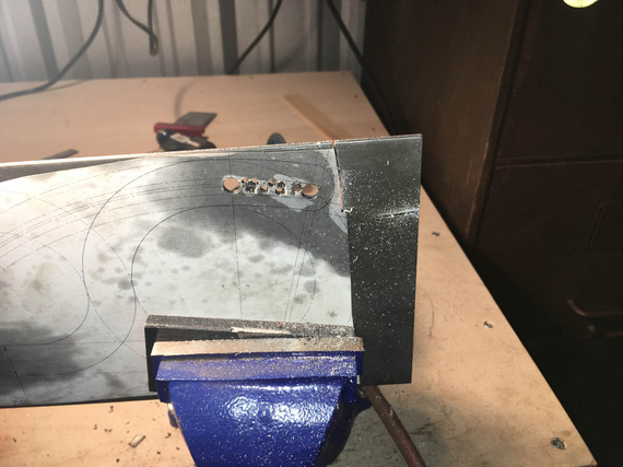
Slot in the making
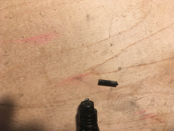
Boo!
Okay, time to go old school... where's that...

Hacksaw!
I cut it out, and cleaned it out with a bastard file.

Cut out

.. and cleaned up
And then, more and more hacksaw...
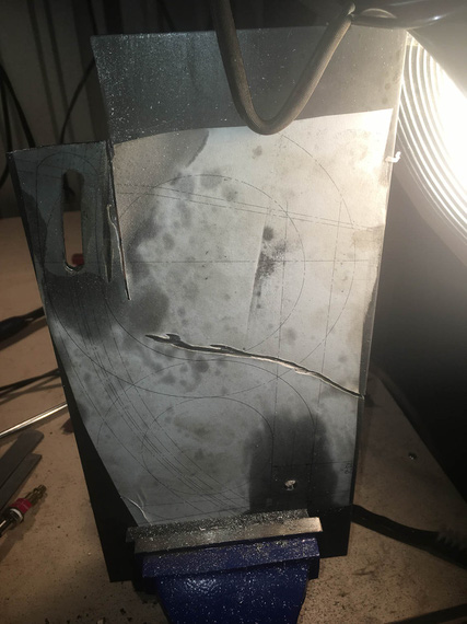
.. my right arm

.. is beginning to feel...

.. it ..
Yeah. The last few inches, I gave up, and used the jig saw. It did cost me 3 blades, but I was too ... done with the hacksaw. I figure, about a blade per 1 inch of cut in 1/8" 4130 with a jigsaw...
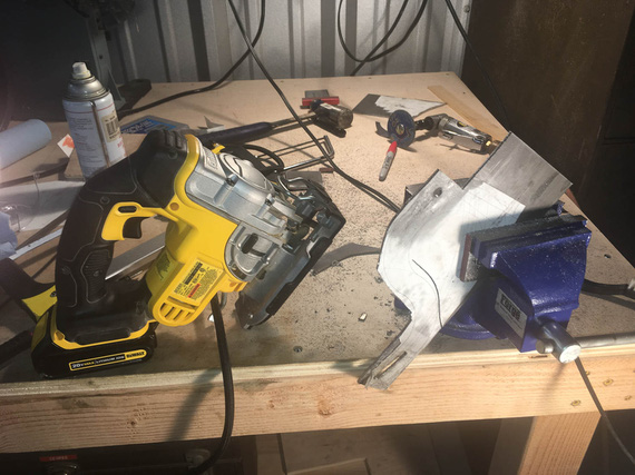
.. gave up.
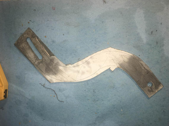
Cutting done.
Looks very ugly, right? Well.... to the grinder!

Grind...
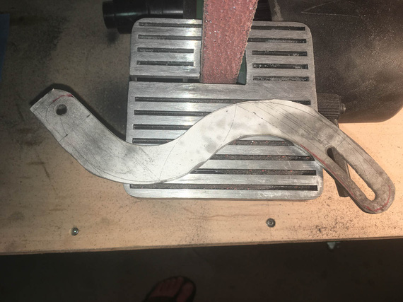
.. grind ..
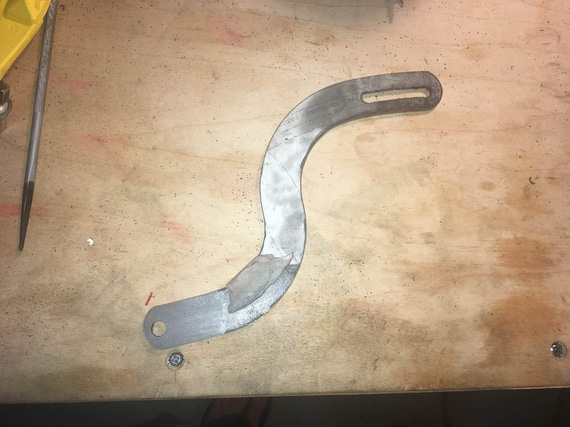
.. grind away ..
Three belts I believe is what it took.
Well, now, the final cleanup on the slot. Yes, Dima, I used the rotary file here :).

Cleaning up the slot
..and, test fit
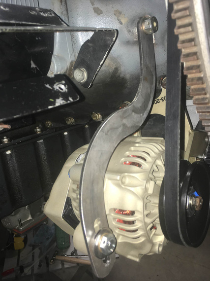
Tadaa!
That was two evenings, folks; but I wasn't done.

The Three Brackets
Next, I had to prep the edges and sand out all the scratches, and paint. A deburring wheel on a bench grinder helped; and the most nasty marks were filed out and then polished out with the deburring wheel.

Clean edge
It has to be done because every scratch is a stress riser - on fittings, every edge needs to be rounded over, and polished.
Finally, to....
Paint
Every airplane "paintjob" I've done so far was in my makeshift "paintboots". Like this one.
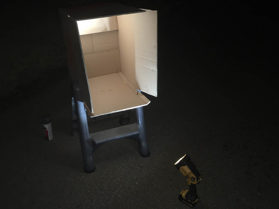
Paintbooth!
I sprayed both the pivot arm, and the baffle support bracket I made earlier, with self-etching primer, and some Rustoleum paint. White will make cracks more visible, if they show up.
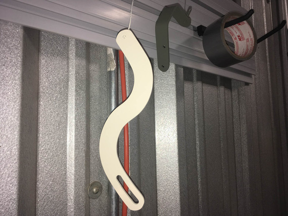
Painted!
So there we go. With this done, I can now install the alternator. Just measly 30 hours to get ready to install the damn alternator! ;)
"Citation 123, if you quit calling me center, I'll quit calling you twin Cessna."
-ORD ATC
Up ↑
Alternator Install: Nose Baffle Support Bracket
...I am Bender, insert girder
| On: | Aug 25, 2019 |
| In: | [Chickenhouse Charger] Electrical Rebuild |
| Time logged: | 9.5 |
| Tags: | 6781G, MA5 Charger, alternator, 4130, fabrication, bending |
As I have thought before, I would need the new nose baffle support bracket, to replace this one:

Old baffle support bracket
...because it would have to now be shorter, fitting in front of the new case mount alternator bracket, over it's right "ear" over here:
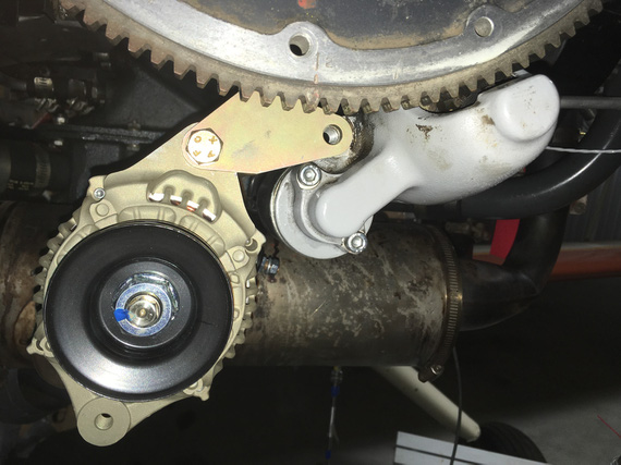
Alternator mount ear and starter
However, prepping to set up to do it, I found this.
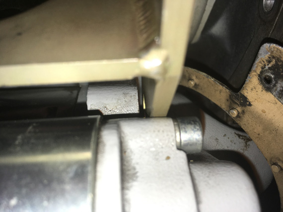
Gap between starter boss and alternator bracket
See that gap between the starter boss "ear" and the new alternator bracket?
Hmmm, methinks.. Maybe, maybe, I can get away without bending up a new, 0.090 steel bracket with weird geometry (it's not a simple "couple bends and you're done" - you'll see later).
Well, let's see.

Old bracket fits nicely in that gap
But it was just a touch too "low". Didn't fit right - and I couldn't raise it (that would raise the holes to which the nose baffle itself attaches, and make the whole thing just not work).
Oh well, I guess we're bending steel after all.
Around that time, my strip of 4130 I ordered from Spruce some days back showed up.
I needed a vice, and a couple more pieces of steel for bending block and such. Picked those up at big box stores (and I will admit, that included a trip to Harbor Freight..).
I also fished out my old small belt sander, and air grinder, from the storage (all my tools are packed up aside from simple hand tools - I am rebuilding my shop; and thanks God I had them close so that I didn't have to rummage thru boxes).
Cutting off a small chunk of an approx. 1/4" thick strip for a bending block is no joke...

... Cutting
My compressor would run out of air, and I'd have to stop, and, while waiting for it to get back to pressure, use hacksaw ('cause I didn't have anything better to do).
Then, I attempted to get away with shoddy bevel grind on the bending block...

Very poorly made bending block
I hoped that that little "cavity" in the middle would work enough to handle bending spring-back - the roundover was fine, just the bevel was uneven.
Ha! Bending a couple of test bends proved me wrong; and that one never gets away with shoddy workmanship.
I re-ground the block to have a nice, even section (all that on a 1x30 belt sander by the way - which I have discovered is perfectly adequate for handling steel with a ~40 grit belt).

A much better bending block
Cut my 4130 strip to width:

Hacksaw!
... and clean up that edge

Edge to be cleaned up
I kinda gave up on it, frankly - got too tired to get it straight and even; and decided to temporarily switch my mind to something else.
Instead, I cut another, test strip, of 4130, without making it to proper width - and attempted to replicate the bracket's geometry on the now much better bending block.
Thinking about how to replicate bend lines, I couldn't think of anything better than... just roughly folding a piece of paper over the old bracket.

Old bracket, test bend, paper pattern, and strip prepared for the new bracket
It worked!
The key was, rather than bending the strip over the block by hand, instead, start the bend by hand, and then finish it with the hammer. I used another piece of 1/4 strip that I cleaned up as an "interface" between the hammer and the material bent, to avoid hammer marks. This way, the bend was much tighter radius (equal to about material thickness, which is what you need for steel), and much easier to control and nudge in the proper direction.
The geometry of the bracket was close enough; the angles were off a bit, but those could be tweaked.
All that bending was one day. I felt done, and left.
Next time I was over at the hangar, I thought, "to hell with it", and decided to use my real strip that I cut out for final bracket.
Used a nice square to draw a reference line, and cleaned up and straightened that edge left over from cutting, marked the first bend line using the paper template left over from my test bend:

Bend mark one
... put it into the vice

Bend one
and bent, using the old bracket for angle reference. That worked out okay, so marked and bent the second bend

Bend two
See the problem? Yep, the first bend is not right on the mark - I did not clamp it right for that first bend. No problem though, I had enough spare length on both ends, so I just moved the location of the second bend accordingly.

Final tweaking by hand

The hole is made, the "ear" is about to be
The hole was drilled with a Unibit, and all the cutting off of small pieces was done with a 3" cutoff wheel on an air die grinder, followed by final tweaking on the 1x30 belt sander.

The ear
And now, the first try.

Did it... work!?
Wow. It might've worked!!! Maybe.. just maybe.. the final test will be if I'll be able to make the holes for the baffle in it.
But for that, we need to position the baffle, and then mark out the holes.
No problem.
Bolt on the old bracket, and hook up the baffle to it. Use anything, whatever, for reference (I used the starter conveniently sticking thru the baffle):

Reference marks set
Then, unbolt old bracket, put the new bracket in, and mark out the holes, while having the baffle back to position marked by reference marks.
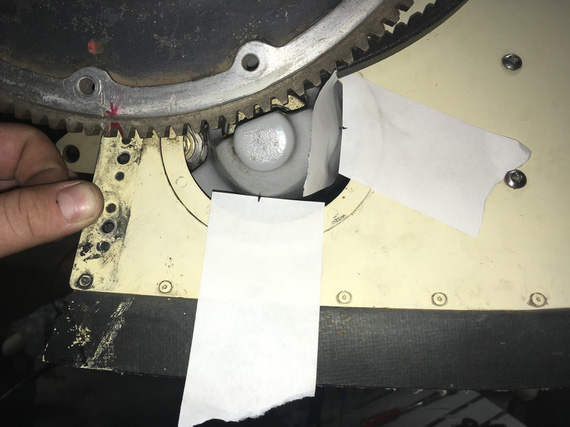
Marking new bracket
Okay, here it is. The final test.

The Two Brackets
Not bad! Given the messed up geometry, me using the paper pattern, my first attempt at bending, it's not that bad at all! Hey, my holes are also not on the center; but the old bracket doesn't have it's holes particularly centered either (and it won the Golden Lindy ;) ).
I guess I'm keeping mine.
I pulled out my nice Cobalt bits I got at Oshkosh to make those holes. At that point I have obtained an old small drill press for the hangar (I had to drill the first, large, hole in the "ear" free hand - even with Unibit that was very annoying).

Sweet metal shavings

Final check

... and, trimmed to size
Emery cloth the whole thing, and it's done.
By the way - you must say - but it's just two bends! How come your holes are not lining up nicely, and such?
Well, this thing has a very messed up geometry. It's two bends, at a non-even angle. This picture probably illustrates this best:

Geometry
Meanwhile, I also had to figure out the alternator's belt length - to make sure it clears all the brackets, and holes in the nose baffle.
I wrote a bit about it in the previous post. Initially I thought that just mocking up the belt, measuring the length of the mockup, and ordering the right size would work - ha!
New belt was too long, and didn't clear the newly made bracket.
Ooookay. Well, I had the belt that's too long (the one I ordered after making the mockup of belt length with a chunk of wire). And, I had the belt that was too short (the one that came with the alternator).
So, I bought all the sizes in between.

Belts!
The one that worked? 7320 :).
... and just to make sure that everything will fit with the new bracket, I ended up putting the nosebowl back on. Didn't want to discover that the nose baffle was sticking out, or not fitting in any other way, when putting the cowling back on.

Bracket - final cut (still temp hardware)

Fit check with nosebowl
OKay. Next - the pivot arm! No bending here. Just lots and lots of grinding.
Meanwhile, all my electrical hardware started showing up! It's like Christmas in August!

Switches

Components
If you push the stick forward, the houses get bigger, if you pull the stick back they get smaller.
© Copyright "79FT". All rights reserved. Feel free to cite, but link back to the pages cited.
This website only shows how I did things in my various projects. These pages are for information and personal entertainment only and not to be construed as the only way, or even the perceived correct way of doing things. You are responsible for your own safety and techniques.
