[79FT]: Building Things |
 |
Alternator Pivot Arm Bracket
lots of grinding
| On: | Aug 31, 2019 |
| In: | [Chickenhouse Charger] Electrical Rebuild |
| Time logged: | 14.5 |
| Tags: | 6781G, MA5 Charger, alternator, 4130, fabrication, drilling, CAD, SWX |
With baffle support bracket done, the next step on the path to alternator happiness was the pivot arm.
The Problem
... was that the default B&C's pivot arm did interfere with the front baffle hookup brackets.
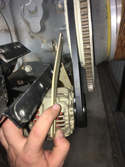
Interference!
That did actually make me pay attention to the very unusual old pivot arm.
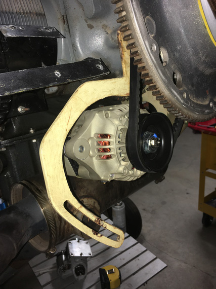
Old one
Nice dogleg, isn't it?
Well, this bracket did not involve any bending, just needed to make the correct one to fit around all the other stuff there on the nose.
Hmm... so how do we do that? Well, first, we need...
The Template
This is not the real template, because (.. read on ;) ). It's the template for the Template.
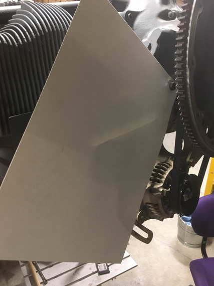
Start with a piece of heavy paper
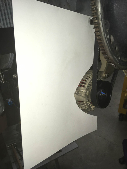
Cut around the alternator
All we need to do with this template is show the location of the hookup hole (top hole, the one that attaches the bracket to the motor); the location of the slot for the alternator to hook up to, and the general outline of the alternator
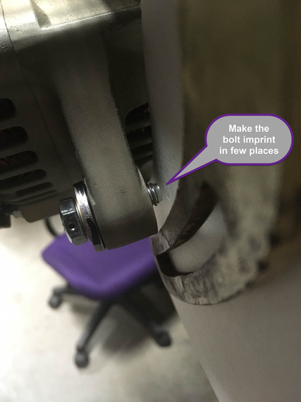
Alternator bolt location is being marked
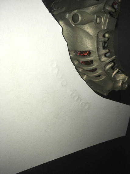
Bolt imprints along the "pivot arc"
..and finally, some more "no go" zones to prevent interference with other brackets there:
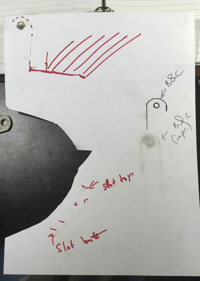
Done!
Notice I also added some "imprints" of the B&C-supplied pivot arm in there, just in case I'd need them.
Okay. I'm lying to you. This template is not the one I used. It was done with the long belt that ended up not working out, so I had to redo the template (thanks God, just the template). The new one was done in the same manner as the one I described above.
Here it is:
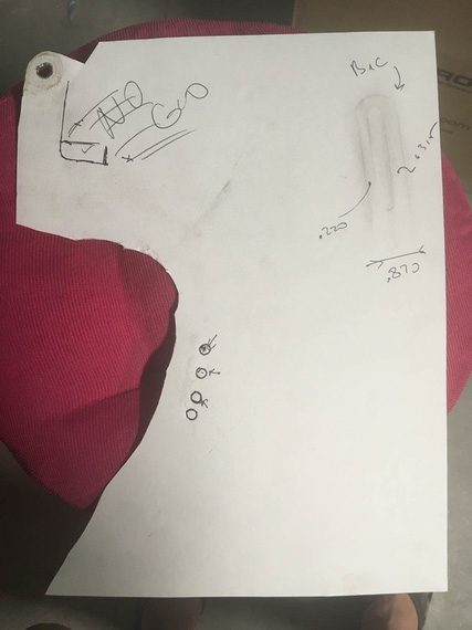
The *actual* template used
Okay. So now, we know critical locations of things and where not to go - so, cue in...
Solidworks!
It's magic, I keep telling people.
So, we take our template, and scan it on a scanner, along with a little metal ruler to give us physical dimensions. Then, we go to Solidworks, start a sketch, and insert the scan as "sketch picture". Using the image of the ruler that was scanned in, we tell Solidworks what "one inch" on this picture is. Boom! The image is now dimensionally accurate.
Then, we start drawing around it.
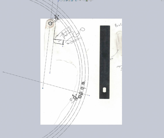
Initial sketch
Above, I positioned the top hole, and the four 5/16" holes around bolt imprints. I then sketched a large circle and made it tangent to three out of four of those holes - it defines the "pivot arc". Then, offsetting it 5/16th gives me the other "side" of the slot; and offsetting it more gives me the "sides" of the bracket in the "pivot arc" area.
I also started sketching the "no go" lines around the top portion of the bracket.
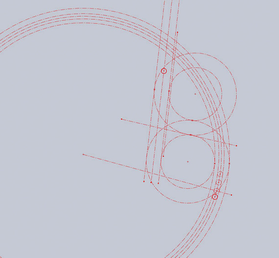
More circles
More circles and lines are added, and off-set. They are not positioned or dimensioned - just made tangent to "no go" lines. You can almost see the outline of the pivot arm, yes? ;)
Now, we take this master sketch; and add arc elements with real lines that we care about.
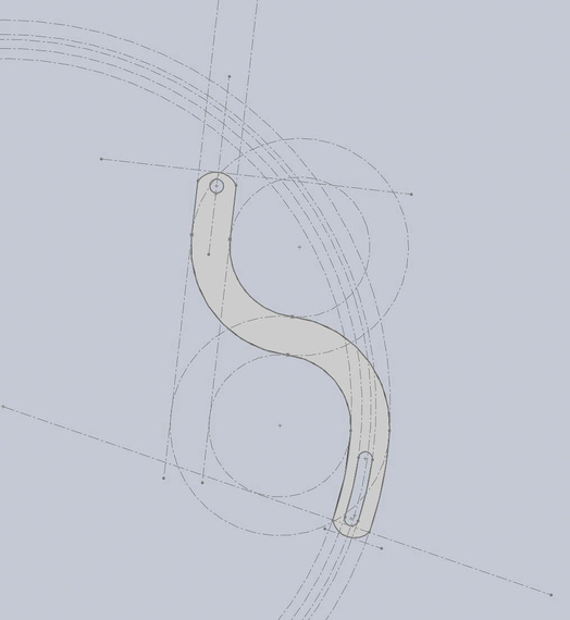
The arm!
Tada! We got the Solidworks Part.
By the way. How do you "measure" the round over of the B&C arm? Radius gauge? Calipers? Hmmm.. Or...
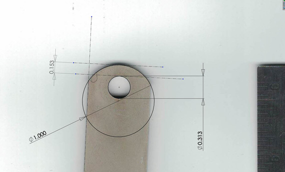
Measuring with Solidworks
Nice, isn't it?
Next, we print the drawing of our new part; making sure our holes' centers are marked (we'll use that later to drill them)
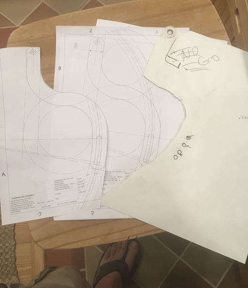
Done!
And, we got ourselves the actual template!
Now, the final test (Many thanks to USPS for providing material for this test)
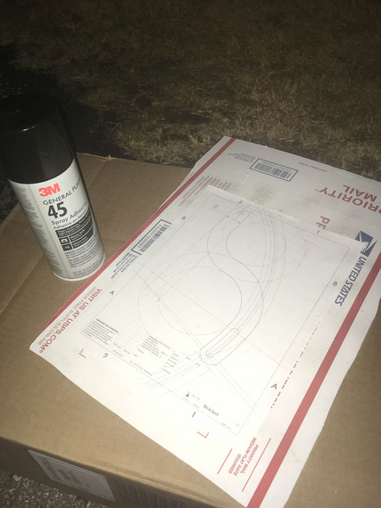
Spray glue and cardboard
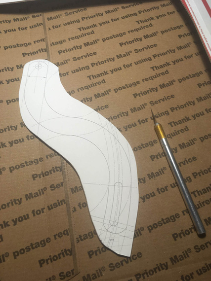
I wish I could cut 1/8" steel with X-Acto...
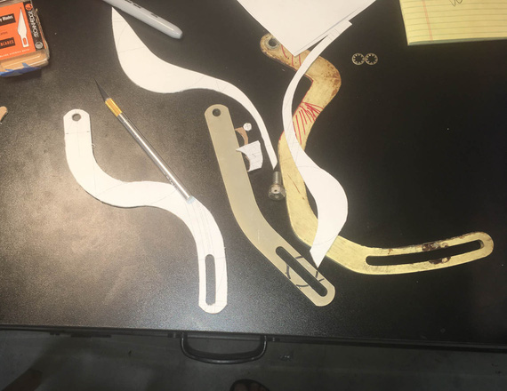
The mockup
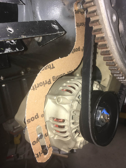
Tadaa!!
Okay, we have the real template now, and we know it'll work. And now, comes...
The Grind
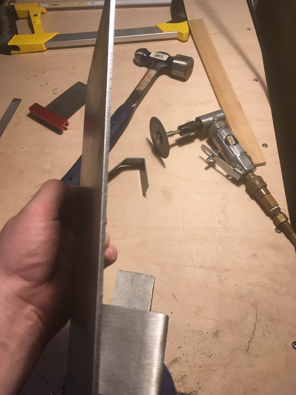
1/8" steel is no joke
Nice little sheet of 1/8" 4130 showed up from Spruce some time earlier... I used spray glue to put the print out of the bracket on top of it.
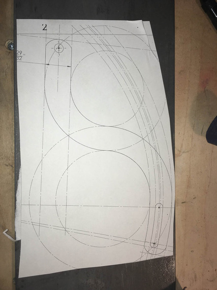
Template on steel
First, all the holes had to be drilled. The drill press I have at the moment is severely underpowered, so I had to step-drill them in four steps.
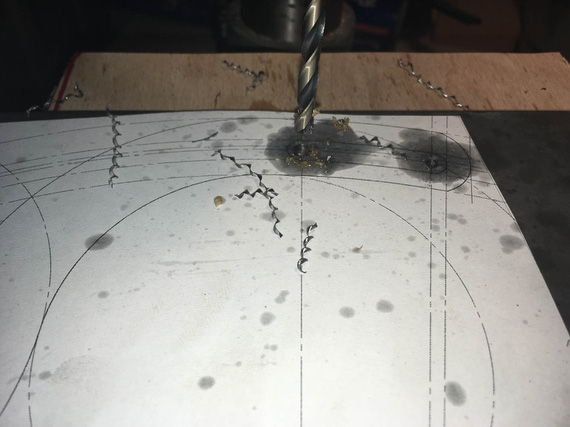
Curlies!
I got to admit, I am starting to become very fond of pretty steel curlies made by nice drill bits.
Also, lesson number one learned: drilling oil (I used TapMagic) gets under the template, and messes up the glue (and unglues it). I need to figure out a better glue.
I drilled the slot's "start" and "end" holes slightly undersized, and reamed the main attachment hole to 5/16ths exactly.
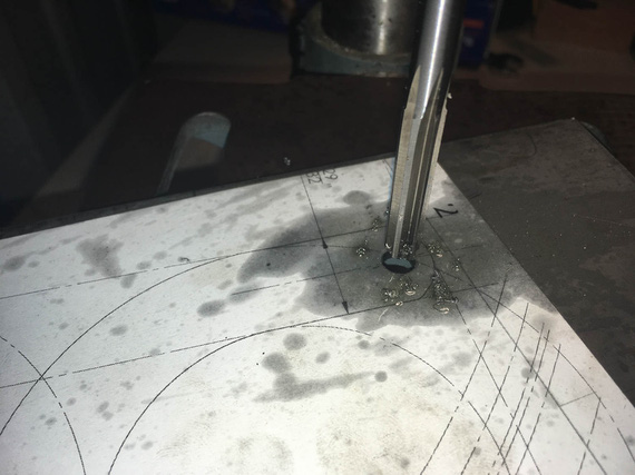
Reamer!
Next, the slot... I rough-drilled small holes around it's perimeter, thinking that a 1/8" shank carbide burr in an air die grinder (basically, Dremel) would work... Ha! It did... for a second ;)
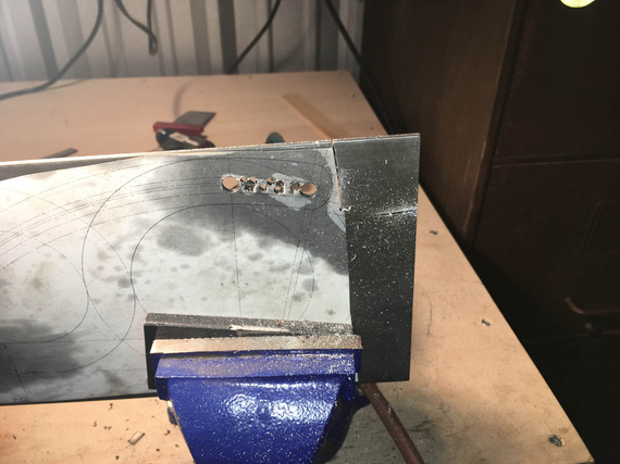
Slot in the making
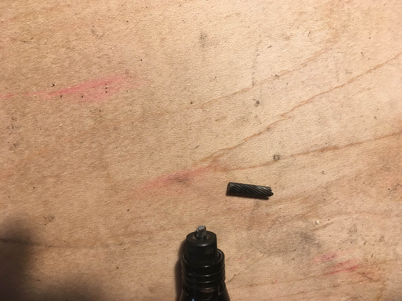
Boo!
Okay, time to go old school... where's that...
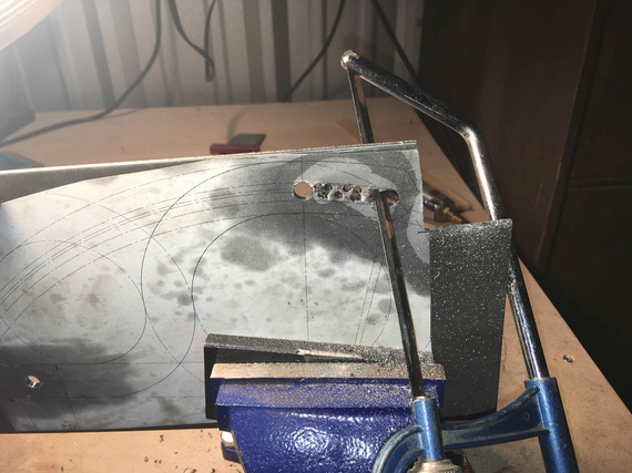
Hacksaw!
I cut it out, and cleaned it out with a bastard file.
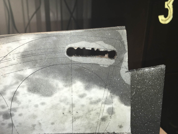
Cut out
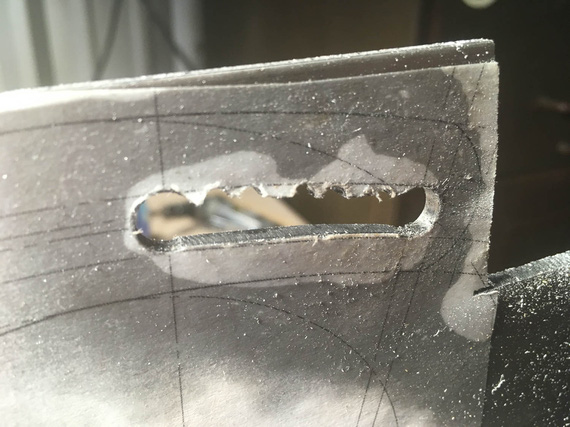
.. and cleaned up
And then, more and more hacksaw...
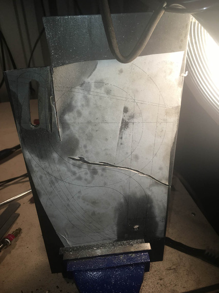
.. my right arm
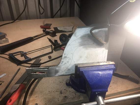
.. is beginning to feel...
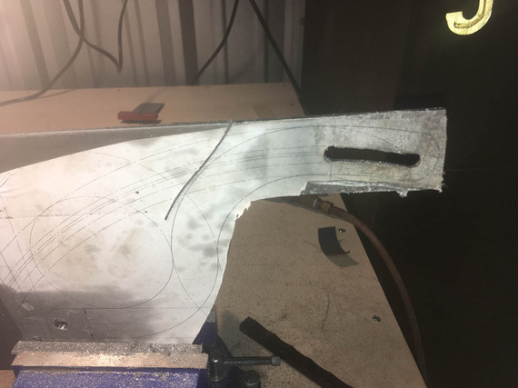
.. it ..
Yeah. The last few inches, I gave up, and used the jig saw. It did cost me 3 blades, but I was too ... done with the hacksaw. I figure, about a blade per 1 inch of cut in 1/8" 4130 with a jigsaw...
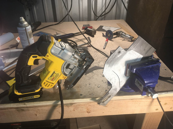
.. gave up.
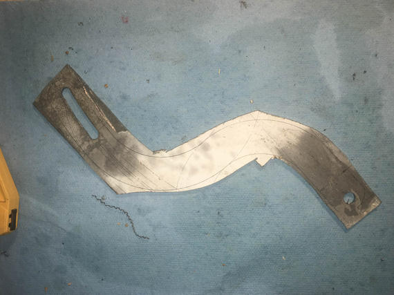
Cutting done.
Looks very ugly, right? Well.... to the grinder!
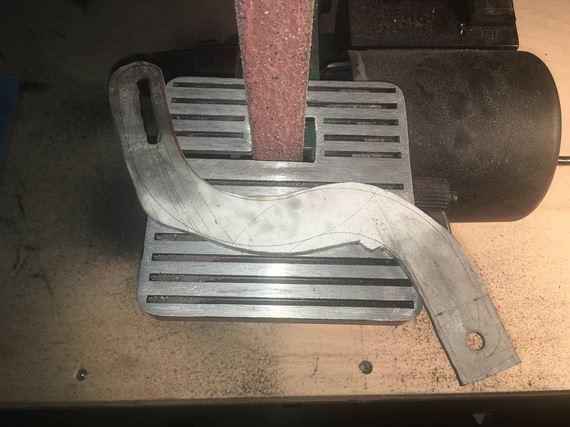
Grind...
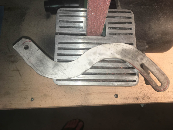
.. grind ..
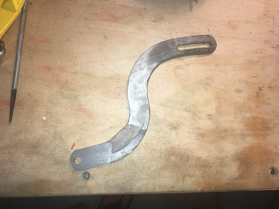
.. grind away ..
Three belts I believe is what it took.
Well, now, the final cleanup on the slot. Yes, Dima, I used the rotary file here :).
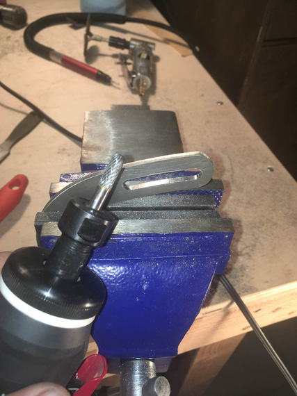
Cleaning up the slot
..and, test fit
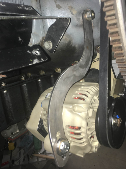
Tadaa!
That was two evenings, folks; but I wasn't done.
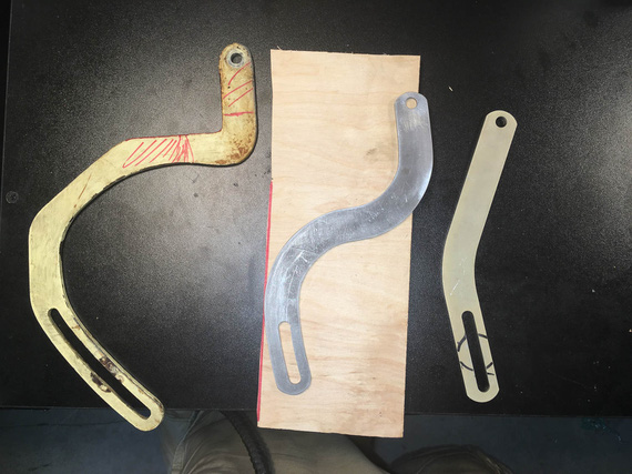
The Three Brackets
Next, I had to prep the edges and sand out all the scratches, and paint. A deburring wheel on a bench grinder helped; and the most nasty marks were filed out and then polished out with the deburring wheel.
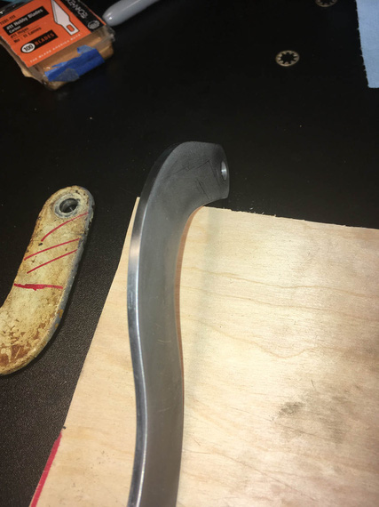
Clean edge
It has to be done because every scratch is a stress riser - on fittings, every edge needs to be rounded over, and polished.
Finally, to....
Paint
Every airplane "paintjob" I've done so far was in my makeshift "paintboots". Like this one.
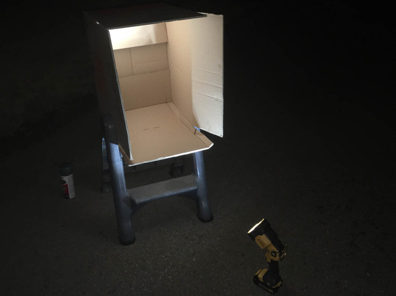
Paintbooth!
I sprayed both the pivot arm, and the baffle support bracket I made earlier, with self-etching primer, and some Rustoleum paint. White will make cracks more visible, if they show up.
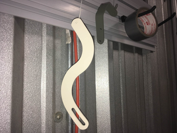
Painted!
So there we go. With this done, I can now install the alternator. Just measly 30 hours to get ready to install the damn alternator! ;)
"Citation 123, if you quit calling me center, I'll quit calling you twin Cessna."
-ORD ATC
Up ↑
© Copyright "79FT". All rights reserved. Feel free to cite, but link back to the pages cited.
This website only shows how I did things in my various projects. These pages are for information and personal entertainment only and not to be construed as the only way, or even the perceived correct way of doing things. You are responsible for your own safety and techniques.